Nomenclature
-
 ${\boldsymbol{\lambda} _j}$
-
Lagrange multiplier vector
-
$\boldsymbol{q}$
-
generalised coordinates
-
$\boldsymbol{T}$
-
kinetic energy
-
$\boldsymbol{V}$
-
potential energy
-
${\boldsymbol{Q}_i}$
-
corresponding generalised force
-
${\boldsymbol{\Psi} _j}$
-
constraint equation
-
$\delta \left( {\boldsymbol{q},t} \right)$
-
relative displacement function
-
$\boldsymbol{F}\left( \boldsymbol{q} \right)$
-
crushing force
-
$\boldsymbol{Kq}$
-
generalised force corresponding to the elastic force
-
${\boldsymbol{Q}_F}$
-
generalised force
-
$\dot {\boldsymbol{M}}\dot {\boldsymbol{q}}$
-
additional inertial force term due to the variation of the mass matrix with time
-
${\boldsymbol{Q}_V}$
-
generalised force associated with the quadratic term of velocity
-
$C$
-
constraint equation
-
$C_q^{}$
-
Jacobian matrix
-
$\lambda $
-
Lagrange multiplier vector
-
$C_q^T\lambda $
-
generalised constraint force


1.0 Introduction
With the continuous advancement of Chinese lunar exploration, manned lunar landing become a key research focus [Reference Niu, Zhang, Mu, Lin, Liu, Bo, Dai and Zhang1–Reference Wang, Xin, Wang and Pan3]. The landing mechanism plays a critical role in the soft landing for manned lunar exploration, enabling stable landings with low overload by impact energy absorption. Currently, most landers are designed based on the structure of the traditional Chang’e series of landers, with the addition of a manned cabin and employing a cantilever beam landing cushioning device. However, this damping approach is weak in the impact energy absorb capacity and landing performance under large load conditions. Unlike previous lunar missions, manned lunar landings must ensure astronaut and equipment safety while significantly increasing payload capacity. Therefore, advancing research on landing cushioning systems for heavy manned lunar modules is both critical and urgent.
So far, only the United States has successfully implemented manned lunar landing missions. Over a period of 41 months beginning on July 20, 1969, the Apollo programme sent 12 astronauts to the lunar [Reference Feng, Wang, Zhu, Li and Wang4]. In October 2017, the United States announced the Artemis lunar landing programme. It is aiming to manned lunar landings by the Orion spacecraft [Reference Liao and Li5, Reference Chen, He, Song and Cui6]. Meanwhile, SpaceX has been actively developing its Starship spacecraft, aiming to facilitate future manned deep-space exploration missions [Reference Yoo7, Reference Zhao, Wang, Hou, Peng and Yu8].
Many researchers focus on the research of the landing mechanisms for landers. The traditional cantilever beam structure remains widely utilised at present [Reference Sun, Zhang, Wu, Li, Yang, Cheng, Xu and Zhang9–Reference Danieli, Masi, Tridello, Pessana, Barato and Chiesa11]. To cope with increasingly complex landing environments, some new landing cushioning structural configurations have gradually been proposed. Wang et al. [Reference Wang, Nie, Chen and Lee12, Reference Wang, Chen, Li, Nie and Lin13] proposed a new type of lunar lander with semi-active control. By referencing the structural dimensions and cushioning mechanical properties of the Chang’e series landers and the Apollo series landers, they designed a detailed structure for the main support legs, aiming to achieve controllable landing damping force and reusability. Zhou et al. [Reference Zhou, Jia, Chen and Chen14, Reference Zhou, Ma, Chen and Tian15] proposed an integrated lander that combines cushioning functionality with lunar surface mobility. They developed a novel cushioning and driving mechanism using a parametric design approach. The rationality of the cushioning mechanism and drive configuration was verified, providing a technical solution for the development of a walkable lander. Jia et al. [Reference Jia, Zhao, Hu, Chen, Zhou and Zhang16] propose a small reusable lander, it uses friction braking to absorb the energy of the landing impact through a set of energy-absorbing components on each landing leg, enabling the fulfillment of mission requirements for multi-position detection on the lunar surface. Wang et al. [Reference Wang, Chen, Dong, Chen, Yuan and Zhu17] proposed a bio- inspired lander from the muscular structure of a domestic cat’s legs. This mechanism fulfills the requirements of controllable overload curves during high impact landings of payloads and enables reusability. Jet Propulsion Laboratory [Reference Connolly18] proposed a mobile lander designed for manned lunar missions and cargo transportation. After landing, it is capable of transporting cargo at a speed of tens of meters per day and can be reused.
Since this century, manned lunar landing exploration and sample return to manned lunar landings become hot topics [Reference Peng, Wang and Xing19–Reference Smith, Craig, Herrmann, Mahoney, Krezel, McIntyre and Goodliff21]. These include the Artemis programme, Mendell programme of the United States and the Chang’e Project of China. The establishment of a lunar base needs transporting humans and equipment to the Moon, which demands on the lander’s payload capacity.
Based on the above analysis, many researchers focus on low-overload landing cushion mechanisms for lunar exploration missions. Therefore, this paper proposes a lander with a higher load-carrying capacity. Through theoretical and simulation analyses, the cushioning performance of the proposed heavy lander is compared with that of the traditional lander under multiple operating conditions to validate its landing performance. The results demonstrate that the proposed manned lunar lander significantly improves load capacity and landing performance.
2.0 Design of landing mechanism for crew lunar vehicles
The landing mechanism determines the efficiency of the cushioning. The traditional lander and the Starship-type manned lander are designed to realise the future manned lunar landing mission.
2.1 Traditional lander scheme and parameters
The traditional manned lunar lander employs a cantilever-type cushioning device, as shown in Fig. 1 [Reference Zhou, Zhou, Deng and Li22], this system consists of an upper module, a lower module, and four sets of landing cushioning devices. The lower end of the main strut is connected to the footpad, while one end of the auxiliary strut is attached to the butt ring, and the other end is linked to the piston barrel of the main strut. The upper module of this lander has a diameter of 4.2 m, with both the upper and lower modules measuring 2.5 m in height, and the total mass is 14 tons. This cantilever beam cushioning structure is widely utilised in the Chinese Chang’e series lunar landers.
Traditional cantilever beam-type manned lander structure and dimensions.

The landing mechanism utilises an aluminum honeycomb structure as a cushioning material, positioned within a designated area inside the landing leg barrel. This honeycomb structure is affixed to a support frame within the landing leg using adhesives, bolts or welds and is constrained by the landing leg assembly during compression to prevent lateral displacement.
Aluminum honeycomb materials are extensively utilised in lunar landing cushioning systems owing to their high energy absorption capacity, lightweight and high-strength characteristics, superior structural stability, effective thermal insulation properties, customisable geometric designs and well-established manufacturing processes. During the landing process, the aluminum honeycombs absorb impact energy by plastic deformation. The hexagonal cell design of the honeycomb structure enables uniform stress distribution during compression, preventing localised overloading and further enhancing energy absorption performance. Its internal cushioning aluminum honeycomb structure parameters are shown in Table 1.
Cushioning aluminum honeycomb parameters

The cantilever-beam landing legs have difficulties in applying auxiliary supports for cushioning vertical kinetic energy. Therefore, the proposed Starship-type manned lunar [Reference Meng, Liu, Yang, Zhou and Zhou23] lander in this paper adopts inverted triangular landing legs. This design aims to address the limitations of traditional landing cushioning, such as insufficient load-bearing capacity and suboptimal cushioning performance under high-mass conditions. It focuses on maintaining low overload throughout the entire landing process under manned conditions.
2.2 Starship-type manned lunar lander
The increased size and weight of the lander enable it to accommodate more personnel and equipment. The lander has a total mass of 26 tons, nearly twice that of traditional landers, with a significantly elevated centre of mass. An inverted triangular landing mechanism is employed for the landing legs. The auxiliary support columns can simultaneously absorb kinetic energy in both vertical and horizontal directions, reducing overload and improving landing stability. The lower end of the inner cylinder of the main/auxiliary support columns is connected to the foot pad via a spherical hinge, while the upper end of the outer cylinder of the auxiliary support columns is connected to the lander body through a spherical hinge. The upper end of the outer cylinder of the main support column is attached to the lander body via a revolute pair, as shown in Fig. 2.
Starship-type lunar lander structure and dimension parameters (landing leg size limits the size of the internal aluminum honeycomb).

The landing mechanism employs an aluminum honeycomb structure as a cushioning material, positioned within a designated area inside the landing leg barrel. This honeycomb structure is affixed to a support frame within the landing leg using adhesives, bolts or welds and is constrained by the landing leg assembly during compression to prevent lateral displacement. During the impact process, the aluminum honeycomb undergoes plastic deformation, effectively dispersing and absorbing the impact energy. The hexagonal cell design of the honeycomb structure enables uniform stress distribution during compression, preventing localised overloading and further enhancing energy absorption performance.
During the cushioning process, assuming the effect of lunar gravity is negligible, nearly all the vertical kinetic energy of the lander is converted into the compression energy of the aluminum honeycomb. Therefore, to ensure adequate cushioning of the lander, the integral of the crushing force of the aluminum honeycomb over the maximum crushing stroke must be greater than the initial kinetic energy of the lander:
 \begin{align}\frac{1}{2}m{v_0}^2 \lt \int_0^{{s_1}} {F{\rm{ }}ds} \end{align}
Where: m is the mass of the lander. v 0 is the vertical landing velocity of the lander. F is the resultant crushing force of the aluminum honeycomb in the vertical direction for all landing legs. s 1 is the maximum crushing stroke.
The dimensions of the landing leg in Fig. 2 limit the maximum crushing stroke of the aluminum honeycomb. The design of the aluminum honeycomb is based on theory analysis and the mechanical properties of honeycomb structures in traditional landers [Reference Li, Deng, Liu and Guo24], with an added margin for cushioning.
Due to the substantial mass of the lander and the exceptionally high yield strength of the aluminum honeycomb in the landing legs, obtaining its mechanical properties through experiments is challenging. Therefore, a simulation-based approach is employed to determine its mechanical properties. To ensure the correctness of the simulation model and simulation method, the crushing processes of a 9 kN specification aluminum honeycomb were compared through crushing simulations and experiments. The aluminum honeycomb has a diameter of 180 mm and a height of 85 mm, and is assigned the material properties of aluminum. The test piece was placed between two fixed pressing plates which are rigid bodies, and the loading speed of the upper pressing plate was 100 mm/min, as shown in Fig. 3.
Aluminum honeycomb compression simulation and experiment.

The crushing simulation and experiment on the aluminum honeycomb material were conducted using the displacement-driven method. During the experiment, the data acquisition system automatically recorded the crushing load and displacement. A comparison between the simulation and experimental results is presented in Fig. 4.
Comparison between the crushing simulation and experiment of the aluminum honeycomb test piece.

It can be observed that a sudden drop in force occurs between 2 mm and 5 mm in the experimental model, which is caused by the instantaneous force reduction due to the sudden crushing and deformation of the aluminum honeycomb. The overall results obtained from the simulation and the experiment show a relatively high consistency, which can validate the accuracy of the simulation model. Based on this finite element method, the crushing simulation of the aluminum honeycomb in the main and auxiliary struts of the two types of landers was further carried out to obtain their mechanical properties. The simulation results are shown in Fig. 5.
Force-displacement curves of aluminum honeycombs for two types of landers. (a) Starship-type lander. (b) Traditional cantilever beam-type lander.

Reducing the buffer force and increasing the buffer stroke are critical to minimising the buffer overload of the lander. Therefore, compared to the two-stage aluminum honeycomb structure used in traditional landers, the crushing force of the aluminum honeycomb in the main struts of the Starship-style lander is reduced, while that in the auxiliary struts is increased.
As observed in Fig. 5 that at the instant of compression of the aluminum honeycomb structure, the crushing force exhibits a stepwise increase, corresponding to the elastic deformation stage and subsequently stabilises during the plastic deformation stage. Once fully compacted, the crushing force rises sharply. However, in the design of landing legs, complete compaction is generally avoided. The stable stage of plastic deformation plays a major role in buffering. In the relevant fields applying aluminum honeycomb buffering, the force-displacement characteristics during this stage are typically approximated as a uniform linear relationship [Reference Wang, Nie, Chen and Lee12, Reference Zhou, Jia and Chen25].
Therefore, according to the size of the landing legs of the lander, the crush force and stroke of the aluminum honeycomb within the main and auxiliary support columns shown in Fig. 6. Specifically, the crush force of the aluminum honeycomb within the main support column is F M1 = 50 kN, with a stroke of L M1 = 750 mm, while the crush force of the aluminum honeycomb within the auxiliary support column is F M2 = 45 kN, with a stroke of L M2 = 550 mm.
Mechanical performance parameters of the primary/secondary struts in the landing cushioning mechanism.

As the impact energy dissipates, the aluminum honeycomb undergoes progressive crushing deformation. The compression stroke is designed to ensure that the aluminum honeycomb is not fully compacted before the lander’s kinetic energy is entirely absorbed.
Unlike previous preliminary lunar explorations, humanity is now focused on establishing lunar scientific research stations, necessitating the transportation of a large number of personnel and supplies. This demand underscores the urgent need for large-payload spacecraft capable of lunar landings. The Artemis programme and the Lunar Gateway programme of the United States, along with China’s Chang’e Project, all aim at this. Based on the analysis presented in this section, the landing cushioning device proposed in this paper demonstrates superior mechanical load-bearing capacity and a greater payload capacity compared to traditional landers.
Based on the analysis presented in this section and the background of the manned lunar landing mission, the total mass of the proposed Starship-type crewed lander has been significantly increased to 26 tons, resulting in a substantial enhancement in payload capacity. This makes it more suitable for manned lunar missions requiring efficient cargo transportation. Additionally, the inverted triangular cushioning mechanism is better optimised for absorbing vertical impact forces. This advantage will be further validated through subsequent simulation analyses.
3.0 Analysis of landing cushion device cushioning dynamics
The landing process of the landing cushioning device proposed in this paper is a typical rigid-flexible coupled impact process. The multibody system includes large-scale rigid body movements of its components, such as the central body of the lander, which can be treated as a rigid structure due to negligible flexible deformation. Additionally, elastic deformations are present, such as the deformable aluminum honeycomb within the cushioning mechanism.
The rigid-flexible coupled dynamics model of the aluminum honeycomb discussed in this paper is based on the first type of Lagrangian equations:
 \begin{align}\left\{ \begin{array}{l}\dfrac{{\rm{d}}}{{{\rm{d}}t}}\left( {\dfrac{{\partial \boldsymbol{T}}}{{\partial {{{\dot{\boldsymbol{q}}}}_i}}}} \right) - \dfrac{{\partial \boldsymbol{T}}}{{\partial {\boldsymbol{q}_i}}} + \dfrac{{\partial \boldsymbol{V}}}{{\partial {\boldsymbol{q}_i}}} - \sum\limits_{j = 1}^C {{\boldsymbol{\lambda} _j}} \dfrac{{\partial {\Psi _j}}}{{\partial {\boldsymbol{q}_i}}} = {\boldsymbol{Q}_i}\\{\boldsymbol{\Psi} _j}\left( {\boldsymbol{q},t} \right) = 0\end{array} \right.\end{align}
Where,
 ${\boldsymbol{\lambda} _j}$
is the Lagrange multiplier vector.
 $\boldsymbol{q}$
is the generalised coordinates of the aluminum honeycomb flexible body.
 $\boldsymbol{T}$
is the kinetic energy of the system.
 $\boldsymbol{V}$
is the potential energy of the system.
 ${\boldsymbol{Q}_i}$
is the corresponding generalised force.
 ${\boldsymbol{\Psi} _j}$
is the constraint equation.
For the aluminum honeycomb inside the landing leg, the constraints include positional constraints, contact constraints and force constraints:
 \begin{align}\begin{array}{l}{C_1}\left( q \right):{q_{\min }} \le q \le {q_{\max }}\\{C_2}\left( q \right):\delta \left( {q,t} \right) = 0\\\boldsymbol{F}\left( \boldsymbol{q} \right) = \boldsymbol{Kq} + C\dot {\boldsymbol{q}}\end{array}\end{align}
Where:
 $\delta \left( {q,t} \right)$
is the relative displacement function of the contact surfaces.
 $\boldsymbol{F}\left( \boldsymbol{q} \right)$
is the crushing force of the aluminum honeycomb.
The kinetic energy of the aluminum honeycomb components corresponding to the generalised coordinates is:
 \begin{align}{T_i} = \frac{1}{2}{\dot {\boldsymbol{q}}^T}M\dot {\boldsymbol{q}}\end{align}
Where:
 $M$
is the mass matrix of the system.
The virtual work of the elastic forces arising from deformation within the aluminum honeycomb flexible structure can be represented using the generalised coordinates of the flexible body as follows:
 \begin{align}\delta {W_e} = - {q^T}K\delta q\end{align}
Where:
 $K$
is the stiffness matrix of the aluminum honeycomb flexible body related to the generalised coordinates
 $q$
.
Substituting Equations (4), into Equation (2) yields:
 \begin{align}M\ddot q + \dot {\boldsymbol{M}}\dot {\boldsymbol{q}} - \frac{\partial }{{\partial q}}\left( {\frac{1}{2}{{\dot {\boldsymbol{q}}}^T}M\dot {\boldsymbol{q}}} \right) + \boldsymbol{Kq} = {\boldsymbol{Q}_F}\end{align}
Where:
 $\boldsymbol{Kq}$
is the generalised force corresponding to the elastic force.
 ${\boldsymbol{Q}_F}$
is the generalised force corresponding to all the impact force acting on the aluminum honeycomb flexible body except the elastic force due to deformation. Including the impact force transmitted through the footpads, the gravitational load of the lander’s central body, the frictional force exerted on the landing leg’s cylindrical wall, and the shear force experienced during cushioning, et al. Define:
 \begin{align}{\boldsymbol{Q}_V} = - \dot {\boldsymbol{M}}\dot {\boldsymbol{q}} + \frac{1}{2}{\left[ {\frac{{\partial M}}{{\partial q}}\dot {\boldsymbol{q}}} \right]^T}\dot {\boldsymbol{q}}\end{align}
Where:
 $\dot {\boldsymbol{M}}\dot {\boldsymbol{q}}$
is the additional inertial force term due to the variation of the mass matrix with time (deformation of the aluminum honeycomb).
 ${\boldsymbol{Q}_V}$
is the generalised force associated with the quadratic term of velocity. Including the nonlinear damping force acting on the aluminum honeycomb during the cushioning process. Therefore, Equation (6) can be written as:
 \begin{align}M\ddot q + \boldsymbol{Kq} = {\boldsymbol{Q}_F} + {\boldsymbol{Q}_V}\end{align}
Then the kinetic equation for a single member is:
 \begin{align}{M^i}{\ddot q^i} + {K^i}{q^i} = {Q^i}_F + {Q^i}_V{\rm{ }}\left( {i = 1,2, \ldots, N} \right)\end{align}
When the dynamic equations corresponding to each component in the lunar lander system are assembled into a matrix and the corresponding constraint equations are added, the rigid-flexible coupling dynamic equations established using the Lagrange multiplier method are as follows:
 \begin{align}\left\{ \begin{array}{l}M\ddot q + \boldsymbol{Kq} + C_q^T\boldsymbol{\lambda} = {\boldsymbol{Q}_F} + {\boldsymbol{Q}_V}\\C\left( {q,t} \right) = 0\end{array} \right.\end{align}
Where:
 $C$
is the constraint equation, which is consistent with Equation. (3) for flexible aluminum honeycomb.
 $C_q^{}$
is the Jacobian matrix of constraint
 $C\left( {q,t} \right) = 0$
.
 $\boldsymbol{\lambda} $
is the Lagrange multiplier vector.
 $C_q^T\boldsymbol{\lambda} $
is the generalised constraint force acting on the aluminum honeycomb flexible body. Including the constraint reaction force resulting from the lunar surface impact, the structural constraint force from the landing leg’s cylindrical wall, and the frictional constraint force.
In an ideal horizontal state, during a lunar soft landing with aluminum honeycomb cushioning, the cushioning force of the aluminum honeycomb can be considered uniform. The dynamic equation governing the soft-landing process is given by:
 \begin{align}Ma = {F_{{\rm{c}}rush}} + c\dot x - Mg\end{align}
Where: M is the mass of the lander. a is the overload acceleration.
 ${F_{{\rm{c}}rush}}$
is the crushing force of the aluminum honeycomb, which is related to the radial diameter of the honeycomb and constrained by the dimensions of the landing leg. c is the damping coefficient of the aluminum honeycomb material.
4.0 Landing dynamic simulation analysis
A simulation analysis of the proposed Starship-type large crewed lunar lander was conducted in ADAMS, and comparisons were made with the traditional lander. The simulation models, as shown in Fig. 7, were both designed to land in a lunar environment with a vertical velocity of 4 m/s. It includes three translational degrees of freedom and three rotational degrees of freedom, as shown in Fig. 8. Resulting in a total of 30 degrees of freedom for all components.
ADAMS simulation model of two landers.

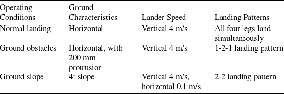
Dynamics simulations were conducted for three typical operating conditions, as shown in Table 2: (1) landing on a normal level surface, (2) landing on a surface with protruding obstacles and (3) landing on a surface with a 4° inclination, where the lander also possesses a horizontal velocity of 0.1 m/s directed downslope. The mechanical parameters of the contact between the lander and the lunar surface are presented in Table 3, with the footpads and lunar surface assumed to follow Hertzian contact theory [Reference Wang, Chen, Li, Nie and Lin13].
Three typical landing conditions for simulation analysis

Mechanical parameters of lander-moon surface contact

Degrees of freedom for lander simulation.

Based on the crushing test of the aluminum honeycomb, the buffering force of the landing legs was modeled as shown in Fig. 6. The three-dimensional model was then imported into ADAMS. The connections among components included translational joints, rotational joints and spherical joints. The buffer force parameters, the initial velocity of the lander, and gravity were set. The time step was 0.01 s, and the termination time was 0.5 s. The GSTIFF solver was employed, utilising the implicit numerical integration method. The solver constructed the equations of motion based on the imported model, solve the nonlinear equations by the Newton-Raphson method and adjusted the time step in conjunction with local error control. Under the three operating conditions listed in Table 2, after applying the equivalent aluminum honeycomb buffering, the buffer forces of the four main struts on the Starship-type lander are shown in Fig. 9.
The buffer force of the main struts on the Starship-type lander during the buffering process. (a) Normal landing. (b) Ground obstacles. (c) Ground slope.

Under normal operating condition, there is an abrupt increase in the buffering force, due to the instantaneous impact when all four landing legs touch the ground simultaneously. In contrast, under other operating conditions, the landing legs touch the ground successively and the kinetic energy of the lander will not decrease substantially at the initial stage, as a result, the buffering force remains relatively smooth.
4.1 Comparison of normal landing
Under normal conditions, the lander touches down vertically, due to the simultaneous collapse of the aluminum honeycomb within the four landing legs, a significant cushioning force is generated, both landers reach peak acceleration at the fastest rate. However, the Starship-type lander exhibits a smoother cushioning process with an extended duration, where its overload remains low after a rapid initial rise. The velocity of the lander’s body reduces to zero at 0.325 s, indicating the end of the cushioning process. Traditional landers experience a stepwise increase in overload due to the action of different aluminum honeycombs. Their cushioning process is primarily concentrated within the first 0.15 s, resulting in a high overload over a short period.
The peak acceleration of the Starship-type lander is approximately 3.64 g, representing a 13.1% reduction compared to the traditional lander. The acceleration and velocity time domain curves are shown in Fig. 10.
Comparison of landers cushioning processes under normal flat lunar surface condition. (a) Acceleration of the two landers. (b) Speed of the two landers.

The compression strokes exhibited by the landing legs of both landers, under normal flat lunar surface condition, display a high degree of similarity among the four groups of legs. Specifically, the average compression stroke of the main strut of the traditional cantilever beam lander measures 323.79 mm, while that of auxiliary strut is 50.86 mm. In contrast, the Starship-type lander experiences a more pronounced compression due to the larger payload, with an average stroke of 520.84 mm for its main strut and 362.31 mm for its auxiliary strut (Fig. 11).
Comparison of the compression stroke of the landing legs of two landers. (a) Starship-type lander. (b) Traditional cantilever beam-type lander.

4.2 Comparison of ground obstacles
When a 200 mm protruding obstacle is present on the landing surface, one of the landing legs touches the ground first at 0.01 s, absorbing part of the kinetic energy. As a result, the peak acceleration of the landers is relatively delayed and lower. Both landers maintain their respective cushioning characteristics, peak accelerations are reduced compared to normal condition, the Starship-type lander exhibits a smoother cushioning process and a longer duration. The peak acceleration is approximately 2.31 g, representing a 23.5% reduction compared to the traditional lander. The acceleration and velocity time domain curves are shown in Fig. 12.
Under the special condition of the lunar surface with protrusions, the compression stroke of the landing legs of the two landers shows notable variation. Specifically, the landing legs that encounter the protrusions undergo significantly greater compression. In the case of the Starship-type lander, the maximum compression of its main strut reaches an impressive 606.61 mm. The conventional cantilever lander’s main strut experiences a maximum compression of 418.48 mm, while the remaining three sets of landing legs demonstrate comparable levels of compression (Fig. 13).
Comparison of landers cushioning processes under lunar surface with protrusions special condition. (a) Acceleration of the two landers. (b) Speed of the two landers.

Comparison of the compression stroke of the landing legs of two landers. (a) Starship-type lander. (b) Traditional cantilever beam-type lander.

Comparison of landers cushioning processes under lunar surface with slope and landers with horizontal velocity special condition. (a) Acceleration of the two landers (b) Speed of the two landers.

4.3 Comparison of ground slope
Under the condition of a 4° inclined surface and a horizontal velocity of 0.1 m/s directed downward along the slope, both landers achieve stable landings. Similar to the previous condition, some landing legs touch the ground first to absorb kinetic energy. However, due to the presence of horizontal velocity, the auxiliary struts also contribute to absorbing horizontal kinetic energy. The traditional lander rapidly reaches its peak overload at the moment when all landing legs touch the ground, forming a sharp contrast with the relatively stable cushioning process of the Starship-type lander. The peak acceleration of the Starship-type lander is approximately 2.04 g, representing a 35.6% reduction compared to the traditional lander (Fig. 14).
Under conditions where the lunar surface is sloped and the landers possess horizontal velocity, the two sets of landing legs positioned uphill experience greater compression. The maximum average compression of the main struts of the Starship-type lander reaches 576.13 mm, whereas that of the traditional cantilever beam-type lander is 365.89 mm. Due to the presence of horizontal velocity, the compression of the auxiliary struts of the traditional lander is greater than in the other two conditions (Fig. 15).
Comparison of the compression stroke of the landing legs of two landers. (a) Starship-type lander. (b) Traditional cantilever beam-type lander.

Based on the comparative simulation analysis, the acceleration of the traditional lander exhibits a characteristic stepwise increase followed by a rapid decrease to zero under all three operating conditions, resulting in significant overload fluctuations.
In contrast, the proposed Starship-type lunar manned lander achieves a stable landing despite a significantly increased payload, with a smooth cushioning curve. The overall load carrying capacity has been improved by 85.71%, while the peak overload has been reduced by 13.1%, 23.5%, and 35.6% under the three operating conditions, respectively.
Regarding the compression stroke of the landing legs, the auxiliary struts of the inverted triangular landing system of the Starship-type lander demonstrate more efficient cushioning in the vertical direction, without reaching their ultimate compression under any of the tested conditions. Due to the use of a single-stage aluminum honeycomb, the crushing force remains uniform throughout compression, and the absorbed energy is directly proportional to the compression stroke.
Therefore, the proposed Starship-type manned lunar lander offers enhanced protection for personnel and equipment, ensuring the smooth execution of manned lunar landing missions.
5.0 Conclusions
To meet the requirements of large payload capacity and low overload for manned lunar landers, a Starship-type lander and its landing cushioning system are proposed. A rigid-flexible coupled impact dynamics analysis is conducted on the landing mechanism, along with a comparative simulation analysis against a traditional lander configuration. Simulation results indicate that the proposed Starship-type lander can achieve a smooth landing with reduced overload under multiple operating conditions, accommodating a total mass of 26 tons. The overall load carrying capacity is increased by 85.71%. The peak acceleration is reduced by 13.1%, 23.5% and 35.6% under three conditions. This design demonstrates excellent load-bearing capacity and landing performance, effectively addressing the limitations of traditional landers, such as high overload and insufficient payload capacity in manned lunar landing missions.
Funding statement
This research was funded by [Basic Research Program (Natural Science Foundation) of Jiangsu Province] grant number BK20210297, [National Natural Science Foundation of China] grant Number 52075242, and [Young Elite Scientists Sponsorship Program by CAST] grant number 2022QNRC001.
Competing interests
The authors declare no conflict of interest.