I. INTRODUCTION
Oxide dispersion strengthened (ODS) materials are promising candidates as cladding tubes for Sodium-cooled fast reactor owing to their excellent mechanical properties. These materials are reinforced by nano-oxides homogeneously distributed within a ferritic/martensitic matrix. In-service, the ODS steels will undergo severe irradiation conditions since the damage dose is expected to reach 150 dpa while the temperature will be ranging from 400 to 600 °C. Reference de Carlan, Béchade, Dubuisson, Séran, Billot, Bougault, Cozzika, Doriot, Hamon, Henry, Ratti, Lochet, Nunes, Olier, Leblond and Mathon1 To guarantee that the excellent mechanical properties will be maintained in-reactor, the stability of the nano-oxides under neutron irradiation has to be assessed. It is worthwhile to emphasize that the understanding of fundamental mechanism governing nanoparticle behavior under neutron irradiation constitute challenges and requires adequate analytical approach as ion beam processing. In the following, results obtained in ODS materials from both irradiation conditions are described.
Under neutron irradiation, Yamashita et al. Reference Yamashita, Akasaka, Ukai and Ohnuki2 reported, in the MA957 alloy, a decrease of the nano-oxide density after irradiation at 500 °C up to 104 dpa, even though they reported no clear change in the nano-oxide size. On the contrary, Gelles Reference Gelles3 observed no significant change on the nano-oxide distribution at 480 °C for the high level dose of 200 dpa in the same alloy. Other authors Reference Yamashita, Akasaka and Ohnuki4,Reference Akasaka, Yamashita, Yoshitake, Ukai and kimura5 observed no nanoparticle dissolution after irradiation, in agreement with Gelles' results. Ribis and Lozano-Perez Reference Ribis and Lozano-Perez6 found that nano-oxides were still dispersed in the ferritic matrix of the MA957 alloy with a slight change on their size and their density after irradiation at 430 °C up to 75 dpa. Concerning, the chemical composition of nanoparticles after irradiation, atom probe tomography (APT) exams on neutron irradiated samples at 330 °C up to 32 dpa Reference Rogozhkin, Aleev, Zaluzhnyi, Nikitin, Iskandarov, Vladimirov, Lindau and Möslang7 showed a high density of fine nanoclusters enriched in yttrium, oxygen, manganese, and chromium, indicating that this composition differs from that of the nonirradiated state since the vanadium had left the clusters.
In parallel to the neutron irradiation experimental studies, many authors contributed to understand the behavior of nano-oxides under irradiation by means of ion beam. Ion beam irradiation offers more practical controls over the range of doses and temperatures that can be reached. Under low damage (0.7, 1, 5, and 10 dpa) at 300 °C Reference Pareige, Miller, Stoller, Hoelzer, Cadel and Radiguet8 in the 12 YWT alloy (Fe–12.3Cr–3W–0.39Ti–0.25Y2O3) and at 500 °C Reference Yutani, Kasada, Kishimoto and Kimura9 in a 19Cr-ODS steel, the nanoparticles were found to be stable. For higher doses, no significant change in particle size was observed using transmission electron microscopy (TEM) up to 20 dpa at 200, 500, and 700 °C in a Fe–19Cr–1.82W–4Al–0.28Ti–0.29Y–0.368Y2O3 alloy, Reference Kimura, Cho, Toda, Kasada, Yutani, Kishimoto, Iwata, Ukai and Fujiwara10 up to 60 dpa at 650 °C in a Fe–16Cr–0.1Ti–0.35Y2O3 alloy Reference Kishimoto, Kasada, Hashhitomi and kimura11 and up to 150 dpa at 670 °C in a Fe–19Cr–2W–4Al–0.3Ti–0.35Y2O3 alloy. Reference Kishimoto, Yutani, Kasada, Hashitomi and Kimura12 In the opposite, a decrease of the nanoparticle average size was reported Reference Certain, Field, Allen, Miller, Bentley and Busby13 after low ion dose (1 dpa) at 525 °C in a Fe–9Cr–1.95W–0.23Ti–0.28Y–0.14O alloy. After irradiation at very low temperature (−75 °C) up to 100 dpa, nanoparticles were completely dissolved Reference Certain, Kuchibhatla, Shutthanandan, Hoelzer and Allen14 while they remain stable at 600 °C in a 14YWT (Fe–14Cr–3W–0.4Ti–0.25Y2O3). In a Fe–18Cr ODS, Lescoat et al. Reference Lescoat, Ribis, Chen, Marquis, Bordas, Trocellier, Serruys, Gentils, Kaïtasov, de Carlan and Legris15 reported that nanoparticles increase in size and decrease in density linearly with t irr 1/3 under irradiation at 500 °C up to 75 and 150 dpa, t being the irradiation duration. By comparing the nanoparticle distribution after irradiation with the nanoparticle distribution after thermal annealing, they found that nanoparticles evolved through a radiation-induced Ostwald ripening mechanism process.
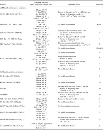
Table I(a) and (b) summarizes the experimental studies conducted by means of both neutron and ion irradiation in ODS materials. From the literature, it can be inferred that nano-oxide distribution appears stable or slightly evolved under neutron irradiation, even for the highest doses. Under ion beam processing, nano-oxides appear to evolve significantly at high enough irradiation dose while they remain stable otherwise.
ODS materials under irradiation extracted from literature: (a) neutron irradiation and (b) ion irradiation.

Analytical approach by ion beam irradiation can bring some fundamental clues on technological issues such as neutron irradiation of cladding materials and overcome some difficulties such as the long irradiation time needed to the materials to reach significant damage value or constraint in handling radioactive samples. It is believed that reaching high damage by means of ions will enhance radiation effects and produce a significant response of the nanoparticle under irradiation. Thus, in the present study, the materials are processed by ion beams with the aim to obtain information on the mechanisms governing the nanoparticle evolution to extrapolate the results to neutron irradiation conditions.
II. EXPERIMENTAL
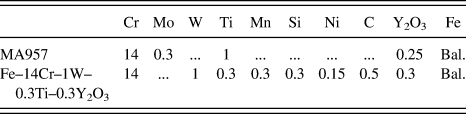
The behavior of nanoscale oxides under irradiation was studied in ferritic ODS steels. These alloys were prepared by mechanical alloying of a ferritic powder with Y2O3 powder and then hot extruded at 1100 °C. Neutron irradiation was conducted on a commercial alloy named MA957, see composition presented in Table II. Ion irradiation was conducted on a Fe–14Cr–1W–0.3Ti–0.3Y2O3 developed at CEA/SRMA for nuclear applications Reference de Carlan, Béchade, Dubuisson, Séran, Billot, Bougault, Cozzika, Doriot, Hamon, Henry, Ratti, Lochet, Nunes, Olier, Leblond and Mathon1 obtained by mechanical alloying in an attritor of prealloyed Fe–Cr–W–Ti powder with Y2O3 powder. The mechanical alloying has been performed under hydrogen atmosphere with prealloyed powders by Aubert & Duval Company. The alloy has been hot extruded at 1100 °C and then annealed at 1050 °C. Its chemical composition is given in Table II.
Chemical composition of the MA957 and the Fe–14Cr–1W–0.3Ti–0.3Y2O3 alloy.

Neutron irradiation of bulk specimen was performed in the French fast neutron reactor named Phenix at 430 °C up to 75 dpa with a maximum flux of the order of 1.3 × 10⁻⁶ dpa s−1. Ion beam processing was performed at the CEA-JANNUS Saclay facility Reference Pellegrino, Trocellier, Miro, Serruys, Bordas, Martin, Chaäbane, Vaubaillon, Gallien and Beck26 using 500 keV Fe+ self-ions with a flux of 2.6–2.8 × 10¹² ions cm−2 s−1 which corresponds to approximately 6.4 × 10⁻³ dpa s−1. Specimens had thin foils geometry, which were maintained at a nominal temperature of 500 °C, and tilted by 15° with respect to the incoming ion beam line.
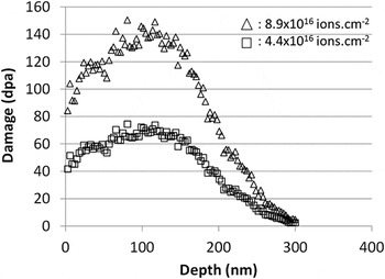
Conversion of SRIM simulation Reference Stoller, Toloczko, Was, Certain, Dwaraknath and Garner27 into dpa was executed after the calculation of irradiation damage under Kinchin–Pease mode in pure Fe with 40 eV displacement energy and 0 eV lattice binding energy. From this calculation, the maximum irradiation dose reached within the 150 first nanometers is 150 dpa. The average ion implantation was estimated at 2.7 at.%. Figure 1 presents the damage profile caused by the 500 keV Fe+ ions implanted in the thin foils.
Depth profile of displacement damage of 500 keV Fe ions in Fe calculated by SRIM using the full detailed cascade method [with E d(Fe) = 40 eV].

TEM was performed using a JEOL 2100 (JEOL Ltd., Tokyo, Japan) operating at 200 kV equipped with a Gatan imaging filter for energy-filtered TEM (EFTEM) and using a JEOL 2010F operating at 200 kV for high-resolution TEM (HRTEM) imaging. The number and density of the nanoparticles before and after irradiation were determined on conventional TEM images. An error bar of ±0.5 nm for particle smaller than 3 nm and of ±0.2 nm for particle larger than 3 nm has been arbitrarily chosen for the nanoparticle diameter measurement. The region thickness for determination of the particle number density was measured by EFTEM. All the regions were chosen to be around 100 nm thick.
EFTEM analytical data were obtained using the three windows method. For the Fe L2,3 edge elemental map, the energy windows were at 638 eV (Pre-edge window 1), 678 eV (Pre-edge window 2), and 728 eV (Postedge window). For the Ti L2,3 edge elemental map, the energy windows were at 406 eV (Pre-edge window 1), 441 eV (Pre-edge window 2), and 476 eV (Postedge window). For the O K edge elemental map, the energy windows were at 514 eV (Pre-edge window 1), 484 eV (Pre-edge window 2), and 547 eV (Postedge window).
III. RESULTS
A. The nanoparticles outside irradiation
It was chosen to study the microstructure outside irradiation in the Fe–14Cr–1W–0.3Ti–0.3Y2O3 material. Although both material microstructures are quite similar, detailed study of the MA957 outside irradiation can be found therein.
Reference Ribis and Lozano-Perez6
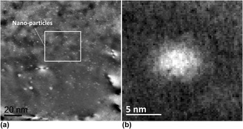
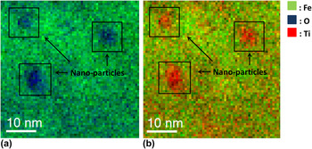
It is worth noting that both of the materials present elongated grains with a size ranging from 1 to 3 µm. Figure 2(a) presents a dark field TEM image of the distribution of nano-oxides within a ferritic grain in the as-received Fe–14Cr–1W–0.3Ti–0.3Y2O3 alloy. The nano-oxides appear to be finely and homogeneously dispersed. Figure 2(b) presents a detailed view extracted from Fig. 2(a) of a 5 nm sized nanoparticle. Owing to their small size, chemical analysis of the nanoparticles is processed using EFTEM. Figure 3(a) shows anticorrelation between Fe and O elemental map. More precisely, it is observed that Fe depletion matches O enrichment. Figure 3(b) shows anticorrelation between Fe and Ti, suggesting that nanoparticles are enriched in Ti. It is worth noting that no Y map was acquired in reason of the difficulty to process Y map
Reference Certain, Field, Allen, Miller, Bentley and Busby13
but as previously demonstrated by APT,
Reference Miller, Kenik, Russel, Heatherly, Hoelzer and Maziasz28
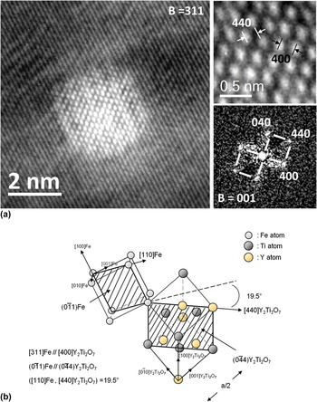
nanoparticles are enriched in Y, as well as Ti and O. Crystallographic exams were conducted on a 5 nm sized nano-oxide as presented on Fig. 2(b). Figure 4(a) is HRTEM image of a nanoparticle along the 100 zone axis. The particles display a cubic symmetry and their (400) and (440) interplanar distances are found to be 0.252 and 0.178 nm, which perfectly match the (400) and (440) Y2Ti2O7 pyrochlore interplanar distances.
Reference Ribis and de Carlan29
Thus, as previously showed,
Reference Ribis and de Carlan29,Reference Béchade, Menut, Lescoat, Sitaud, Schlutig, Solari, Llorens, Hermanges, de Carlan, Ribis and Toualbi30
nanoparticles are supposed to display a pyrochloric-like crystallographic structure with a space group Fd3m.
Reference Menut, Béchade, Cammelli, Schlutig, Sitaud and Solari31
The lattice structure of the pyrochlore oxide is closely related to the fluorite structure except that there are two cation sites and one-eighth of the anions are absent (8a). Anion vacancies occur in a pyrochlore by virtue of the oxygen deficiency inherent in an A2B2O7 compound.
Reference Ribis and de Carlan29
The Y and Ti metal cations occupy the 16d(1/2, 1/2, 1/2) and 16(0, 0, 0) sites, respectively, and the oxygen is in the 48f(x, 1/8, 1/8) and 8b(3/8, 3/8, 3/8) positions.
Reference Ribis and de Carlan29
Related to the nanoparticle on Fig. 4(a), the orientation relationship in the host ferritic matrix of the pyrochlore structure is depicted on Fig. 4(b). This orientation relationship resumed as (311)Fe/(400)Y2Ti2O7 and
 $\left( {0\bar 11} \right){\rm{Fe}}//\left( {0\bar 44} \right){{\rm{Y}}_2}{\rm{T}}{{\rm{i}}_2}{{\rm{O}}_7}$
is one among other already observed.
Reference Ribis and de Carlan29,Reference Ribis, Lescoat, Zhong, Mathon and de Carlan32
Figure 5(a) proposes a high-resolution detailed view of a
 $\left( {1\bar 11} \right)$
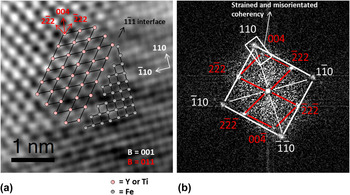
interface between nanoparticle and matrix and Fig. 5(b) is the corresponding fast Fourier transform (FFT). Their orientation can be described as (110)Fe//(004)Y2Ti2O7 and (001)Fe//(110)Y2Ti2O7. It can be inferred that matrix and nanoparticle display a strained and misoriented coherent relationship along the [110] direction while other directions are likely to be incoherent. The interface topology appears as being flat and sharp.
Nanoparticle distribution within a ferrite grain: (a) dark field TEM image of the nanoparticle distribution and (b) detailed view of a single nano-oxide.

EFTEM images of nanoparticles: (a) anticorrelation between Fe and O maps and (b) anticorrelation between Fe and Ti maps.

Structure and coherency of the nanoparticle: (a) HRTEM image of a nanoparticle along the [001] axis and (b) Orientation relationships between matrix and nanoparticle.

Sharp and flat interface structure of a nanoparticle: (a) HRTEM image of a [111] interface and (b) corresponding FFT.

B. The nanoparticles under ion irradiation
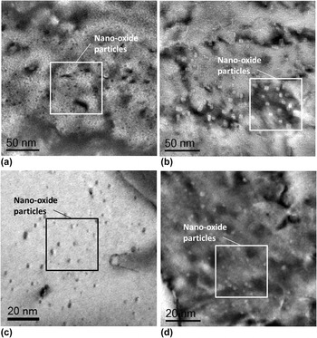
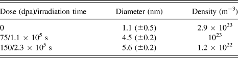
Figure 6(a) presents the nano-oxide dispersion without irradiation in the Fe–14Cr–1W–0.3Ti–0.3Y2O3. The nanoparticle density is estimated to be 2.9 × 10²³ m−3 while the average size is 1.1 nm. After ion irradiation, at 500 °C up to 150 dpa, the nano-oxide dispersion had significantly evolved as suggested by Fig. 6(b). As compared to the nonirradiated state, the average size increased from 1.1 to 5.6 nm while the density decreased from 2.9 × 10²³ m−3 to 1.2 × 10²² m−3.
Nanoparticle distribution prior and after irradiation: (a) nanoparticle distribution in Fe–14Cr–1W–0.3Ti–0.3Y2O3 alloy outside irradiation, (b) nanoparticle distribution in Fe–14Cr–1W–0.3Ti–0.3Y2O3 alloy after ion irradiation at 500 °C up to 150 dpa, (c) nanoparticle distribution in the MA957 outside irradiation, and (d) nanoparticle distribution in the MA957 after neutron irradiation at 430 °C up to 75 dpa.

The growth of the nano-oxide could also be appreciated by their shape transition from sphere to cuboid. Table III summarizes the average size and density of the nanoparticles for the different irradiation conditions. The average size was calculated by considering the largest edge dimension in case of the cuboid-like shaped particles.
Average size and density of nanoparticles after ion irradiation.

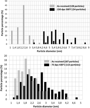
Figure 7(a) presents the size distribution of the particles before and after ion irradiation. The corresponding histograms are representative of a single grain. It could be observed that the irradiation induced a shift of the size distribution that illustrates the increase in diameter of the particles. The disappearing of the particles smaller than 3 nm is also observed.
Histogram of the size distribution of the nanoparticles: (a) in the as-received Fe–14Cr–1W–0.3Ti–0.3Y2O3 alloy, and in the ion irradiated Fe–14Cr–1W–0.3Ti–0.3Y2O3 alloy (150 dpa at 500 °C), (b) in the as-received MA957, and in the neutron irradiated MA957 (75 dpa at 430 °C).

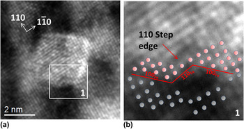
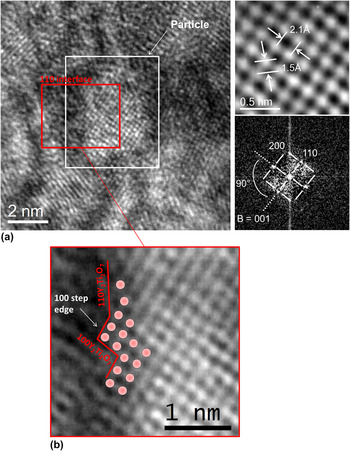
As shown on Fig. 8(a) and detailed in Fig. 8(b), irradiation also modifies the topology of interfaces which displays a [110] step edge. Such a topology may be associated to radiation-induced dynamical roughening. Reference Bellon and Enrique33 Dislocation emission from the precipitate to relax the stress induced by coherent precipitation may be another explanation. However, no steps at the particle interface were observed prior irradiation, even in the coarsened particles. Reference Ribis and de Carlan29
Interface after ion irradiation in the Fe–14Cr–1W–0.3Ti–0.3Y2O3 alloy: (a) high resolution image of the interface and (b) detailed view showing the step edge along the [110](Fe) direction.

C. The nanoparticles under neutron irradiation
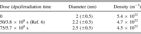
Figure 6(c) presents the nano-oxide distribution without irradiation in the MA957 alloy. The nanoparticles are finely dispersed with an average size of 2 nm and a density equal to 5.4 × 10²² m−3. After neutron irradiation, at 430 °C up to 75 dpa, the distribution of nano-oxide appears to have slightly evolved and the shape transition from sphere to cuboid occurred [Fig. 6(d)]. As compared to the nonirradiated state, it can be concluded that the nanoparticle average size slightly increased from 2 to 2.5 nm, while their density slightly decreased from 5.4 × 10²² m−3 to 4.5 × 10²² m−3.
Table IV summarizes the average size and density of the nanoparticles for the different irradiation conditions. The average size was calculated by considering the largest edge dimension in case of the cuboid-like shaped particles.
Average size and density of nanoparticles after neutron irradiation.

Figure 7(b) presents the size distribution of the particles before and after neutron irradiation. The corresponding histograms are representative of a single grain. It could be observed that the irradiation induced only a slight shift of the size distribution. Particles with size less than 2 nm start to disappear.
Figure 9(a) presents a nanoparticle after neutron irradiation with distinguishable interface and a structure matching a Y2Ti2O7 type structure. As observed after ion irradiation, the interface does not have the equilibrium flat configuration, but presents step edge [Fig. 9(b)]. From this, it can be concluded that nanoparticle interfaces are destabilized under neutron irradiation.
Interface after ion irradiation in MA957: (a) high resolution image of the interface plus FFT and (b) detailed view showing the step edge along the [100](Y2Ti2O7) direction.

IV. DISCUSSION
A. Ostwald ripening under ion irradiation
As suggested by Fig. 2(a), ODS materials are characterized by a fine dispersion of nanoparticles dispersed within a ferritic grain. Such a distribution of nanoparticles embedded in the Fe host matrix could be considered as a high concentration of interfaces giving rise to excess in the free energy of the system. From this excess in the free energy, it results a driving force for particle coarsening. However, atomic exchanges are sluggish due to the low diffusion coefficient of Y and the large complexity of nano-oxide structure (Y2Ti2O7), leaving nanoparticles at a small size even when the material is annealed at high temperature. Reference Ribis and de Carlan29 Therefore, atomic displacements caused by ion irradiation can disturb the kinetics and release the thermodynamic driving forces that lead the nanoparticle system to coarsen. This phenomenon is named radiation-induced Ostwald ripening and will be called hereafter ORI (Ostwald ripening under irradiation). Briefly, nano-oxide atoms can be knocked out by recoils of the collision cascade and will be deposited outside the particle in the surrounding matrix. Reference Heinig, Müller, Schmidt, Strobel and Möller34 Thus, in addition to the thermal detachment of atoms at the interface, detachment will be caused by ion beam mixing. Once in the surrounding matrix, the ejected atoms will be mobile due to the supersaturation of vacancies. Ejected atoms can return toward the particle or be transported away to another particle, ensuring the coarsening of the particle system. Recently, Lescoat et al. Reference Lescoat, Ribis, Chen, Marquis, Bordas, Trocellier, Serruys, Gentils, Kaïtasov, de Carlan and Legris15 proved that nano-oxides in ODS material undergo radiation-induced Ostwald ripening when the material is ion irradiated at 500 °C up to 150 dpa since the particle diameter elevated at the power 3 varies linearly with the irradiation time. They verify that when the material is irradiated at low temperature (25 °C), the diffusion process is dramatically slow and ballistic effect dominates. Under this condition, the ejection of atoms at the interface is readily proved, since nanoparticles were completely dissolved. Whereas at 500 °C, nanoparticles have coarsened with a similar rate to thermal annealing at 1300 °C, proving the radiation-enhanced transport of ejected atoms toward other particles. Thus, since our condition of irradiation is strictly the same than that of Lescoat et al., Reference Lescoat, Ribis, Chen, Marquis, Bordas, Trocellier, Serruys, Gentils, Kaïtasov, de Carlan and Legris15 the same approach consisting in plotting the diameter evolution of the particles regarding to the irradiation doses is used for the ion irradiated Fe–14Cr–1W–0.3Ti–0.3Y2O3 alloy to estimate the particle growth kinetic in function to the irradiation conditions.
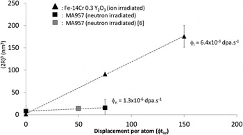
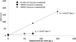
Figure 10 is a plot of the particle diameter elevated at the power 3 [(2R)3] versus the displacement per atom after ion irradiation (to compare with neutron irradiation, dpa are chosen for abscissa instead of irradiation time). It is found that the variation of (2R)3 varies linearly with the dpa. Hence, in accordance with the results of Lescoat et al., Reference Lescoat, Ribis, Chen, Marquis, Bordas, Trocellier, Serruys, Gentils, Kaïtasov, de Carlan and Legris15 the increase in size and decrease in density reported in the present study [Figs. 6(a) and 6(b)] under ion beam irradiation can be interpreted in terms of radiation-induced Ostwald ripening. As already mentioned, another consequence of this process is that interfaces display step edge [Figs. 8(a) and 8(b)].
Plot of the nanoparticle diameter elevated at the power 3 versus the displacement per atom after ion and neutron irradiations.

Once the mechanism with which nanoparticles evolved under irradiation has been identified, can this process be extrapolated to explain the nanoparticle response under neutron irradiation?
B. Ostwald ripening under neutron irradiation
First, under neutron irradiation, cascades are expected to be of different size than those created by ion irradiation since the mass and the energy of the bombarding particle differ. Nevertheless, as observed in Fig. 4, nano-oxide interfaces are sharp and flat and not diffuse, thus, to displace an atom out of the particle, the relocation range must exceed the nearest neighbor distance value, which is achieved in both cases whether the incident particle is an energetic neutron or an ion. Hence, atomic ejection at the nano-oxide interface is also expected under neutron irradiation.
Concerning the vacancies, as under ion irradiation, they will be produced in supersaturation until they reach the concentration fixed by the steady state. Thus, under neutron irradiation, radiation-enhanced transport of solute atom is also expected. Then, ORI is very likely to rule the nanoparticle behavior under neutron irradiation.
Evidence of ORI under neutron irradiation could be the interface structure, since nano-oxides display nonequilibrium step edge that may result from ballistic jump of atoms at the interface as already identified under ion irradiation. Thus, one can reasonably think that the slight increase in size and decrease in density of nano-oxide under neutron irradiation can also be explained by ORI process. The plot of the nanoparticle diameter elevated at the power 3 [(2R)3] against the dose (or irradiation time) [Fig. 10] appear to confirms this hypothesis. It is observed that (2R)3 varies linearly with the dose (or irradiation time). However, the increase in size of the particles is too small to provide an accurate kinetic analysis, in addition the linearity dependence of the diameter regarding the irradiation time is also observed for various exponents. Thus, no conclusions are made on the kinetic law governing the particle growth under neutron irradiation. Although no quantitative chemical study has been conducted, the HRTEM clearly shows that nanoparticles display the equilibrium Y2Ti2O7 structure after neutron irradiation [Fig. 9(a)]. It could be inferred that ORI drives the nanoparticles toward the Y2Ti2O7 stoichiometry as demonstrated by Lescoat et al. Reference Lescoat, Ribis, Chen, Marquis, Bordas, Trocellier, Serruys, Gentils, Kaïtasov, de Carlan and Legris15
C. Particle growth kinetics difference between under ion and neutron irradiation: Flux effect
If one considers the rate of growth of nanoparticles regarding the irradiation time, it can be pointed out that the coarsening kinetics is largely slower in case of neutron irradiation (Fig. 10). ORI kinetics is ruled by the ratio of atomic relocations caused by cascade and thermal attachment at the interface and by the vacancy supersaturation ensuring solute diffusion. This phenomenon may be different regarding the irradiation conditions. Hence, to give a first explanation of this large difference, it is assumed that particle diameter elevated at the power 3 varies linearly with the irradiation time in the case of neutron irradiation (Fig. 10).
From Fig. 10 and considering the irradiation time instead of dose, it can be deduced that the slope for ion irradiation is roughly 4 orders of magnitude above that corresponding to neutron irradiation. The slope ratio is roughly equal to 5 × 10⁴, i.e., the particle growth rate is roughly 30 times faster under ion than under neutron irradiation. According to the coarsening theory and in a first approximation, by considering that
 $T_{\rm{i}}^{{\rm{irr}}}$
and
 $T_{\rm{n}}^{{\rm{irr}}}$
(the ion and neutron irradiation temperatures) are close values, the slope ratio of nanoparticle growth rate could be given by:
 $${{\bar R_{\rm{i}}^3 - \bar R_{\rm{i}}^3\left( 0 \right)} \over {\bar R_{\rm{n}}^3 - \bar R_{\rm{n}}^3\left( 0 \right)}} \approx \left( {{{D_{\rm{i}}^{{\rm{irr}}}} \over {D_{\rm{n}}^{{\rm{irr}}}}}} \right)\quad ,$$
Where R
i and R
n are the particle diameters under ion and neutron irradiation, respectively,
 $D_{\rm{i}}^{{\rm{irr}}}$
and
 $D_{\rm{n}}^{{\rm{irr}}}$
are the atomic diffusion coefficient under ion and neutron irradiation, respectively, corresponding to the Y diffusion coefficient. Under neutron and ion irradiation, the atomic diffusion could be expressed as
Reference Lescoat, Ribis, Chen, Marquis, Bordas, Trocellier, Serruys, Gentils, Kaïtasov, de Carlan and Legris15
:
 $${D^{{\rm{irr}}}} = {{C_{\rm{V}}^{{\rm{irr}}}} \over {C_{\rm{V}}^{{\rm{eq}}}}}{D^{{\rm{th}}}}\quad ,$$
Where D
th is the thermal atomic diffusion coefficient,
 $C_{\rm{V}}^{{\rm{eq}}}$
and
 $C_{\rm{V}}^{{\rm{irr}}}$
are respectively the equilibrium and irradiation concentration of vacancies. In the steady state controlled by sinks,
 $C_{\rm{V}}^{{\rm{irr}}} = \varphi \tau$
, with
 $\varphi$
the radiation flux and τ the time to reach the steady state. Hence, expression (1) could be written as:
 $${{\bar R_{\rm{i}}^3 - \bar R_{\rm{i}}^3\left( 0 \right)} \over {\bar R_{\rm{n}}^3 - \bar R_{\rm{n}}^3\left( 0 \right)}} \approx \left( {{{\varphi _{\rm{i}}^{{\rm{irr}}}} \over {\varphi _{\rm{n}}^{{\rm{irr}}}}}} \right)\quad .$$
For a neutron flux ranging from 10−7 to 1.3 × 10⁻⁶ dpa s−1, the slope ratio is found to be ranging from 4.9 × 10³ to 6.4 × 10⁴, i.e., the particle growth rate is found to be roughly 17 to 40 times faster under ion than under neutron irradiation, values compatible with the measured one. Therefore, this analysis suggests that if the mechanisms responsible for nanoparticle evolution under ion and neutron irradiation above 400 °C are the same, the main difference being that ion irradiation, performed at higher flux, induces and accelerates evolution. Further, the rate growth of nanoparticles should scale as
 ${\varphi ^{{1 \mathord{\left{\vphantom {1 3}} \right\kern-\nulldelimiterspace} /3}}}$
.
V. CONCLUSION
To conclude, difficulties in interpreting nano-oxide system response under neutron irradiation can be overcome by ion beam processing of ODS materials. In this study, the radiation-induced Ostwald ripening is identified as the mechanism governing the nanoparticle response under ion irradiation. The result is the increase in size and a decrease in density of the finely dispersed Y2Ti2O7 nanoparticles. Under neutron irradiation, ORI appears to be less effective resulting in a lower nanoparticle growth rate probably because radiation flux is much lower than in ion irradiation. Our analysis allows to suggest that for a given dose, the nanoparticle kinetics should scale as
 ${\varphi ^{{1 \mathord{\left{\vphantom {1 3}} \right\kern-\nulldelimiterspace} /3}}}$
,
 $\varphi$
being the radiation flux.
ACKNOWLEDGMENTS
This study was made in the frame of a tripartite agreement between the CEA, AREVA NP and EDF. Irradiations at SRMP-JANNUS Saclay were performed thanks to the funding of the EMIR network. JR acknowledges J-L. Béchade, D. Sornin, and M. Le Flem for scientific support of the study.