I. INTRODUCTION
Microwave technology has been used for a long time to improve safety in aviation. Different technologies have been used to avoid collisions and help in guidance and landing, especially at night and during bad atmospheric conditions. One of the most important technologies used for this purpose is radar technology. Radar technology started to be intensively developed during World War II, and since that time the powerful primary surveillance ground-based radars have been applied for air traffic control [Reference Griffiths and Willis1]. Also during World War II, active airborne radars were introduced to service and used to detect other planes, bombsights, and as a runway finder [Reference Buderi2]. On-board radar systems were expensive, very complicated, and heavy, so only combat aircraft were equipped with active radars [Reference Buderi2].
The application of active transponders, replying to requests of secondary radars and transmitting their own position obtained from an on-board global positioning systems (GPS) receiver, significantly improved the safety and quality of information about all users of the air zone. However, this technique does not eliminate many threats since non-cooperative targets do not respond and it is difficult to avoid collisions with such objects.
In the last decade, the rapid progress in unmanned air vehicles (UAVs) can be observed. The manned remote control of such objects is possible only for small distances, when optical visibility between the UAV and its operator is ensured. The use of on-board optical cameras can help significantly, but this technology is limited by down-link properties and fails during bad weather conditions and low light during night-time.
The situation can be improved by adding active radars that provide situation awareness to autopilots to help in avoiding collision. The required instrumentation range of the radar depends on the maximum relative speed between the targets, radar scan time, and the assumed reaction time of the platform. Assuming relative speed between targets is of the order of 600 m/s, a radar scan time of 5 s, and a required reaction time of 5 s, the minimal radar detection range should be not smaller than 12 km (assuming three scans for proper target behavior identification). The detected radar cross section (RCS) should be at the level of −20 to −10 dBsm to detect not only aircraft but also UAVs. This requirement leads to radar devices with a mean transmitting power of 20–100 W and with advanced antenna and signal processing systems. The extensive application of active radar systems will lead to an increase of “electromagnetic pollution”, and while many similar radars can work in the same band, this can result in serious interference problems.
An alternative approach uses the passive radar. As the passive radar does not emit any energy it can be small, lightweight, and have a low power consumption, required only for data acquisition and processing block. However, to make a reliable on-board passive radar, several theoretical and engineering problems must be solved.
II. PASSIVE RADAR TECHNOLOGY
The on-board passive radar has to receive signals from all available emitters of opportunity and observe the area of interest to detect the potential threats. It requires multi-beam adaptive antenna arrays to track illuminators and targets in the vicinity. While passive radars are highly dependent on emitters of opportunity, the flight-path should be planned in such way that proper radar coverage is available during the whole mission.
The passive radar does not illuminate targets with its own transmitter, but it exploits commercial transmitters of opportunity existing in the area of interest. These transmitters should have sufficient emission power, a good property of cross-ambiguity function of the transmitted signal, and high-enough-frequency bandwidth.
The requirement of a proper shape of the cross-ambiguity function is related to the range and Doppler resolution of the radar. The good cross-ambiguity function means that there exists a sharp peak of the cross-ambiguity function and the side-lobes are small enough to make detection of small targets possible in the case of heavy clutter. The range and velocity resolution should be comparable with modern active radars; required accuracy in range is 10–200 m and 1–5 m/s in velocity. Additionally, the properties of the cross-ambiguity function should be time invariant, to ensure the required performance over 24 h/day.
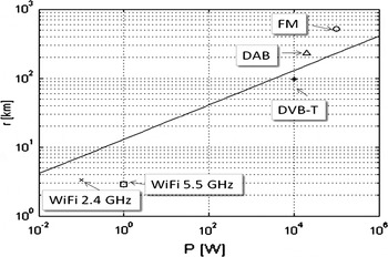
The existing passive coherent location (PCL) radars are the ground-based ones exploiting FM radio emissions [Reference Howland, Maksimiuk and Reitsma3–Reference Baker, Griffiths and Papoutsis7, Reference Malanowski, Mazurek, Kulpa and Misiurewicz25]. Several PCL radar demonstrators exploiting other emissions also exist, such as digital terrestrial TV (DVB-T) [Reference Gould, Pollard, Sarno and Tittenso8, Reference Kuschel, Glende, Heckenbach, Mller, Schell and Schumacher9], digital radio (DAB) [Reference Kuschel, Glende, Heckenbach, Mller, Schell and Schumacher9–Reference Poullin and Flecheux11], satellite TV (DVB-S), analogue TV [Reference Howland12], cellular phone networks (GSM) [Reference Nickel13, Reference Samczynski, Kulpa, Malanowski, Krysik and Maślikowski14], internet links (WiFi, WiMax) [Reference Colone, Falcone, Bongioanni and Lombardo15], and many more. The possible PCL detection ranges versus transmitting power using selective, 8 dB gain receiving antennas at a frequency of 500 MHz are plotted in Fig. 1 (assuming 0 dBsm target, 8 dB system losses, 12 dB detection threshold, and an almost monostatic configuration). The example detection range for typical illumination of opportunity (also using an 8 dB gain receive antenna) is also plotted.
Selection of emitters of opportunity.

The aforementioned requirements for airborne PCL systems limit in practice the choice of transmitters of opportunity to the ones with a powerful, continuous digital emission. At present, two candidates exist: DVB-T and DAB. The illumination from satellites: digital DVB-S and GPS have small radiated power, thus the receiving antenna system will be complicated and heavy, and only possible to install on a large, man-operated aircraft. Due to low power density the practical detection range will be limited to ca. 4 km but coverage is very good as practically the entire land area of the world is covered by DVB-S, and the whole globe is covered by GPS. Moreover, the coverage of GLONAS and GALILEO is expanding.
The DAB emission is one of the potential candidates with 1.5 MHz bandwidth and related 100 m range resolution. For the DAB emission two bands are designated – UHF: 174–240 MHz (replacing TV channels 5–12) and L: 1452–1492 MHz. The first one is better suited for bigger platforms, as the single λ/4 antenna element is 40 cm long, while the second, not popular at the present time, can be applied for UAV in the future.
The DVB-T is now under rapid development, and in all European Union countries it will have replaced analog TV within the next few years. The typical frequencies are 400–800 MHz, with a transmitted power of 10–100 kW and a bandwidth of about 8 MHz. The range resolution is 20–30 m, almost independent of the contents of the transmission. The velocity resolution depends on integration time, and a resolution of 1 m/s can be reached. A single-antenna element is 10–20 cm in size; therefore, it is possible to construct the antenna array on medium-sized UAVs also. To increase the possible number of channels available for all TV viewers, the single-frequency network concept is applied in DVB-T. All transmitters within the country transmitting this same program are using the same frequency. All transmitters are synchronized in time and frequency by GPS signals. Thus, a single receiving channel in passive radar can be used, while the target is illuminated by several transmitters.
The passive radar detects the targets by calculating the cross-ambiguity function:

where X T is the reference signal, received by the beam directed toward the transmitter, X R(t) is the signal from the surveillance beam, t i is the integration time, F is the carrier frequency, w(t) is the weighting function, and * represents conjugation. The target bistatic range r and velocity v are estimated as the coordinates of the maximum of function given by equation (1). The use of the cross-ambiguity function provides the processing gain equal to the (bandwidth × integration time) product:

In theory, the processing gain could be as high as the designer requires, but in practice the integration time is limited by the time in which the target remains in the range and Doppler resolution gate. For the passive radar using the DVB-T illuminator of opportunity, the range gate size is 20 m, and for airborne targets with a maximum relative speed of 1200 m/s the maximum integration time is 16 ms. The maximum integration gain is thus 130 000 (51 dB).
The target will be detected if the echo power is higher than the radar receiver sensitivity.
The minimum detectable power P d in passive radar is
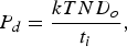
where k is the Boltzmann constant, T is the equivalent receiver temperature, N stands for total losses, and D o is the detection threshold (usually 13 dB). For DVB-T radar with 16 ms integration time, the minimum detected echo power is −140 dBm. The echo power in free space conditions is equal to
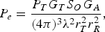
where P T is the transmitted power, G T is the transmitter antenna gain (toward the target), S O is the target RCS, G A is the receive antenna gain (toward the target), r T is the transmitter-to-target distance, r R is the target-to-radar distance, and λ is wavelength.
The received antenna gain is usually 5–15 dB. The transmitter antenna gain is 5–10 dB but only in the horizontal direction, as to provide good ground coverage. For high-altitude targets, the gain is much weaker, and in many cases targets are illuminated by the antenna side-lobes, where the gain to the target is −30 to −10 dB.
Additionally, due to the presence of the ground reflection, illumination (as well as receiving) should always be treated as a multipath process, as illustrated in Fig. 2.
Multipath effect.

The illumination signal consists of two components: direct and reflected from ground. Ground reflection shifts signal phase by 180°, and due to this low-flying targets can have lower illumination (fading effect), described by the following formula:

where A is the complex reflection coefficient, X is the transmitted (complex) signal, and ΔR is the multipath range difference. The change of power due to multipath versus range difference (normalized to range resolution gate) is plotted in Fig. 3. It is worth mentioning that if the range difference is greater than the range resolution cell then there is no power loss.
Power losses due to multipath effect.

Taking into consideration all the effects mentioned above, it is possible to calculate the target echo power received by passive radar in any selected scenario. More interesting, however, is the minimum detectable target RCS for the given probability of detection (0.5 in presented case). In Fig. 4, the detected RCS, for the on-board radar placed on a plane flying at 1 km altitude using a DVB-T transmitter (30 kW) placed 30 km from the plane, is presented. As it is shown, it is possible to detect all targets at flight level and below, while high-flying targets (above 5 km) are almost invisible to radar, due to weak illumination.
Minimum detectable RCS in dBsm – platform height 1 km.

A high-flying object has a much more difficult situation. In Fig. 5, the scenario with platform flying at 9 km is presented. In this case, it is possible to detect targets within 5–10 km at the flight level and good detection is also present at a height of up to 1000 m.
Minimum detectable RCS in dBsm – platform height 9 km, (a) vertical projection, (b) XY projection at flight level “o” plane position, “*” – transmitter position.

In all simulated scenarios sufficient coverage at flight level was achieved, so the PCL system can be used for air platform collision avoidance.
One of the basic problems in passive airborne radar is the cancellation of ground clutter. In a ground-based PCL system, ground clutter has no Doppler spread and can easily be cancelled using an adaptive lattice filter [Reference Kulpa16, Reference Malanowski, Kulpa, Mordzonek and Samczynski17, Reference Kulpa26]. In a PCL radar placed on a moving platform, the clutter signal has a significant Doppler spread caused by the platform's motion [Reference Brown, Woodbridge, Stove and Watts18–Reference Kulpa, Malanowski, Samczynski and Misiurewicz20]. The clutter-free region is limited in range by the platform elevation (when only a direct signal competes with the target echoes) and in Doppler by the platform velocity. Using the classical Doppler spread clutter cancellation method described in [Reference Malanowski, Kulpa, Mordzonek and Samczynski17], not only the clutter but also the targets of interest can be cancelled.
The other possibility is to apply adaptive space-time processing (STAP) to cancel the ground clutter [Reference Kulpa, Malanowski, Samczynski and Dawidowicz19, Reference Dawidowicz, Kulpa, Malanowski, Misiurewicz, Samczynski and Smolarczyk21, Reference Dawidowicz, Samczynski, Malanowski, Misiurewicz and Kulpa22]. The classical STAP algorithms are derived for active radar, where all sounding pulses are the same. In a PCL system, the illuminating signal is continuous, and due to changes of information content the time-shifted parts are not identical. As a result, STAP algorithms for airborne PCL systems have to be modified to obtain the required properties.
III. EXPERIMENTS WITH MULTI-CHANNEL RADAR
To gain a deeper knowledge of the PCL signal properties, a set of experiments were performed at the Radar Technology Lab at the Warsaw University of Technology (WUT). The first part of the experiments were performed using a Raw Radar Signal Simulator, simulating the scenario using FM radio and DVB-T signals for scene illumination. The second part of the experiments was performed using a Passive Radar Demonstrator mounted on-board of the Skytruck airplane. The signals from all six antennas were amplified by selective FM band COTS amplifiers (88–108 MHz) and directly digitized and down converted. The IQ signals from two selected FM channels (100 kHz bandwidth) were recorded on the hard drive and processed off-line.
A) Computer simulations
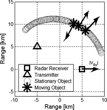
The simulation geometry is presented in Fig. 6. The radar scene consists of a group of stationary scatterers (marked with circles) and three moving targets (asterisks). The radar receiver (square) moves toward the right with a constant velocity V S. The stationary transmitter of opportunity (triangle) illuminates the radar scene. All targets are placed on a constant bistatic range ellipse, so they occupy exactly the same range cell.
PCL simulation geometry.

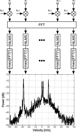
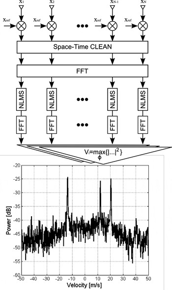
During the simulation experiments two processing schemes were tested: the subband Space Time Adaptive Processing for passive radars (Fig. 7) described in detail in [Reference Dawidowicz, Samczynski, Malanowski, Misiurewicz and Kulpa22] and the subband STAP augmented by adaptive direct signal removal using CLEAN-type processing [Reference Malanowski, Kulpa, Mordzonek and Samczynski17] (Fig. 8).
STAP processing diagram.

CLEAN + STAP processing diagram.

In the first scenario presented in Figs 7 and 8, the reference signal consists of a direct signal, and the measurement signal consists only of a signal reflected from the objects on the radar scene. Both methods provide similar results and all three targets are visible as the separate peaks ca. 15 dB above the processing floor. In the second, more realistic scenario, the reference signal remains the same, but direct signal cross-talk was added to simulate the measurement antenna cross-talk. Computer-based simulations were performed for two types of transmission: FM radio and DVB-T. The assumed carrier frequencies for FM and DVB-T were 100 and 600 MHz, respectively. The bandwidth of the simulated signals was 50 kHz (FM) and 8 MHz (DVB-T). The coherent integration time in all simulations was equal to 1 s.
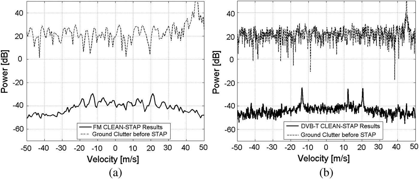
Figure 9 presents the results of the processing of the simulated data case when the direct signal cross-talk was about 50 dB above the target's echo. Such a value is typical in PCL radars. All objects are masked by strong processing sidelobes. The peak associated with the cross-talk indicates the relative bistatic velocity between the transmitter and the mobile radar receiver. For example, in the stationary radar case this peak would occupy a zero-velocity bin. The application of the CLEAN algorithm suppresses the direct signal together with its sidelobes (Fig. 10). The three targets of interests are clearly visible. The remains of the direct signal after a CLEAN processing can be easily spotted around 45 m/s (Fig. 10). The simulation shows the advantage of the DVB-T signal. Due to its higher carrier frequency, the received Doppler bandwidth is higher compared to the FM radio signal. Therefore, the processing gain is also higher.
PCL STAP results for scenario 2: (a) FM-based simulation, (b) DVB-T-based simulation.

PCL CLEAN-STAP result for scenario 2: (a) FM-based simulation, (b) DVB-T-based simulation.
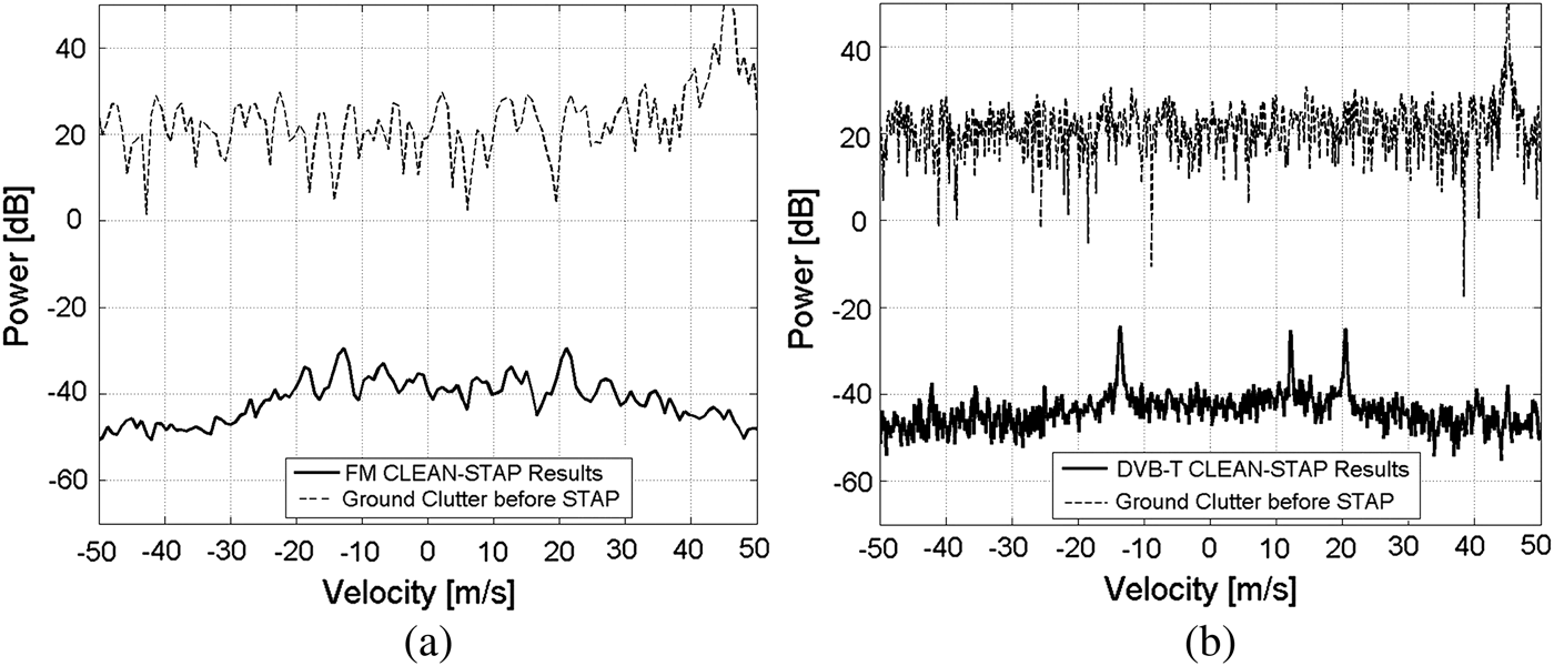
The computer simulations proved that the direct use of classical STAP does not ensure good results, while combining the CLEAN technique [Reference Malanowski, Kulpa, Mordzonek and Samczynski17] for direct signal cancellation with a modified STAP approach gives a significant improvement.
B) Real-life measurements
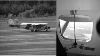
Up to now, only FM-based experiments on moving platforms, namely on a car platform [Reference Dawidowicz and Kulpa23] and on a Skytruck airplane [Reference Kulpa, Malanowski, Samczynski and Dawidowicz19, Reference Kulpa, Malanowski, Misiurewicz, Mordzonek, Samczynski and Smolarczyk24], were carried out at the WUT Radar Technology Laboratory. The measurement campaigns with the PCL system mounted to the airborne platform were carried out close to the Polish coastline of the Baltic sea in May 2008 and April 2009. The radar was equipped with a six-element antenna array – three on each side of the airplane. The antenna elements were placed inside the aircraft in the window openings (Fig. 11). The signals were directly digitized, digitally down-converted, and recorded on the hard drive. To obtain the final results off-line, processing was applied, consisting of digital beam-forming, a CLEAN algorithm removing the direct signal from the measurement beam, and subband STAP processing.
Bryza airplane (left) and the FM antenna mounted temporarily at the plane window (right).

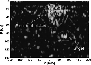
The result of the signal processing using a combination of both methods is presented in Fig. 12. It can be seen that the residual clutter returns are present in the picture, but also the target is clearly seen.
Detection results using CLEAN method combined with simplified STAP – amplitude (in dB scale) color coded.

The residual clutter can mask some of the slow targets, so further development of efficient signal processing algorithms is required.
IV. CONCLUSION
The paper presents the idea of an airborne passive radar dedicated for aircraft and UAV platforms for air surveillance, with the intention of increasing air safety and to avoid collisions in air-space. It was shown that the detection range is sufficient to provide the detection of near targets, and thus help in collision avoidance. It can be used for man-operated platforms, but the main benefits will be in connecting the PCL radar output to a collision-avoidance function of autopilot to provide safety for unmanned platforms. The first trials on passive airborne radars performed in Poland [Reference Kulpa, Malanowski, Samczynski and Dawidowicz19, Reference Kulpa, Malanowski, Samczynski and Misiurewicz20, Reference Kulpa, Malanowski, Misiurewicz, Mordzonek, Samczynski and Smolarczyk24] and England [Reference Brown, Woodbridge, Stove and Watts18] show that this technology can be used in the near future. The use of FM radio is not optimal for this purpose, due to a narrow band (ca. 3 km range resolution) and changes of its properties depending on the content of the broadcast (music and speech). Thus, in further experiments, a DVB-T signal will be used. The coverage diagrams shown in Figs 4 and 5 do not include the detection losses due to direct signal cancellation, which can significantly degrade the passive radar sensitivity at the direction of the transmitter, but the use of multiple transmitters can mitigate this problem.
ACKNOWLEDGEMENTS
The authors would like to thank the Polish Ministry of Science and High Education for their support under the research grant 5525/B/T00/2010/39 and the Polish Coast Guard for their cooperation. Part of this work has been also supported by the European Union within the framework of the European Social Fund through the Warsaw University of Technology Development Programme.
 Krzysztof Kulpa received his M.Sc. and Ph.D. degrees in electronics from the Warsaw University of Technology, Warsaw, Poland, in 1982 and 1987, respectively.
He is currently an associate Professor at the Warsaw University of Technology and is head of the Signal Processing Laboratory. Prior to this, he was associate professor at Technical University of Bialystok (1988–90). In 1990–2005, he was a scientific adviser at RADWAR S.A.
Mr Kulpa is the author/coauthor of over 200 scientific papers. His research interests involve radar signal and data processing including detection, tracking, PCL, SAR, ISAR, and noise radars.
He is a senior member of IEEE and a member of EUMA and AOC. He was the Chairman of the Polish chapter of IEEE SPS (2003–05) and at present is the vice-chairman of the joint Polish chapter IEEE AESS/AP/MTT. He is a program committee member of several radar conference series such as IRS (2004–12), EUSAR (2002–12), EURAD (2007–11), RADARxx (2008–10), FUSION (2006–10), among others. He was the initiator of the Signal Processing Symposium (SPS) conference series and the chairman of SPS (2003–11).
 Mateusz Malanowski received his M.Sc. and Ph.D. degrees in electronics from the Warsaw University of Technology, Warsaw, Poland, in 2004 and 2009, respectively.
He was a Research Scientist with FGAN (Forschungsgesellschaft fuer Angewandte Naturwissenschaften), Germany, and an Engineer with Orpal, Poland. Currently, he is an Assistant Professor at the Warsaw University of Technology. Dr Malanowski is the author/coauthor of over 60 scientific papers. His research interests include radar signal processing, target tracking, passive coherent location, synthetic aperture radar, and noise radar.
Dr Malanowski is a member of the Institute of Electrical and Electronics Engineers (IEEE) and Institution of Engineering and Technology (IET).
 Piotr Samczynski received his Ph.D. degree in telecommunications from the Warsaw University of Technology, Warsaw, Poland in 2010. He received his B.Sc. and M.Sc. degrees in electronics from the Warsaw University of Technology, Warsaw, Poland in 2004 and 2005, respectively.
Since 2010, he has been employed as an Assistant Professor at the Warsaw University of Technology. Prior to this position, he was employed as a research assistant at the Przemyslowy Instytut Telekomunikacji S.A. – PIT S.A. (2005–10), where in 2009–10 he was the head of Radar Signal Processing Department in PIT S.A. He has been an Editor Assistant of Journal Transactions of PIT in 2009–11.
He is the author/co-author of over 60 scientific papers. His research interests are related to radar signal processing, SAR (Synthetic Aperture Radar) techniques, PCL (Passive Coherent Location), and DSP (Digital Signal Processing) algorithms.
 Jacek Misiurewicz was born in Warsaw, Poland on March 26, 1965. He received his M.Sc. and Ph.D. degrees in electronics engineering from the Warsaw University of Technology in 1988 and 1996, respectively. Since 1988, he has been involved with the Institute of Electronics Fundamentals (now the Institute of Electronic Systems) at the Warsaw University of Technology fulfilling the posts of teaching assistant and assistant professor in the area of digital signal processing.
He was involved in several research projects granted from European and national institutions, as well as development projects granted from the Polish radar industry, in the area of digital processing of radar signals. His interests include non-uniform sampling problems, compressed sensing applications, MTI filtering and filter design, SAR and PCL technology, as well as programmable logic applications, and real-time programming. He is the author/co-author of over 60 research papers.
Dr Misiurewicz was a member of Organizing and Program Committees of many national and international conferences. He also serves as a reviewer for IEEE journals. He has been a member of IEEE since 1993 (Senior Member since 2003), and served as IEEE Poland Section Newsletter Editor from 1998 to 2004.
 Bartek Dawidowicz received joint M.Sc. and B.Sc. degrees in electronics from Warsaw University of Technology, Warsaw, Poland, in September 2004. He has been a Ph.D. student at the Warsaw University of Technology since 2004. He worked as a research and development contractor at Warsaw University of Technology (2004–07) and as a research engineer in the Advanced Signal Processing Team at Mitsubishi Electric R&D Center Europe–UK, Visual and Sensing Division (2008–11). He is currently the algorithms engineer at Aeroflex Test Solutinos. His research interests are associated with digital signal processing techniques for mobile communications and radar imaging. Mr Dawidowicz is the author/coauthor of 34 scientific papers. He was the creator and the core member of the Radiolocation and Digital Signal Processing (RDSP) Student's Research Group between 2003 and 2007. He is currently an honorary member of the RDSP Student's Research Group.