I. INTRODUCTION
Microstrip low-pass filters (LPFs) are widely used in the wireless communication systems to suppress unwanted harmonics and spurious signals [Reference Hong and Lancaster1]. Several methods have been presented in recent years to reach desirable performance, such as compact size, low insertion loss, wide stopband, and sharp roll-off. For example, defected ground structure [Reference Xu, Ma, Meng and Yeo2–Reference Wang, Ning, Xiong and Mao5] and electromagnetic (EM) band gap cells [Reference Jung and Chang6, Reference Huang and Lee7] have been used to reduce the occupied size and suppress the unwanted harmonics of the LPFs. Unfortunately these methods usually require backside etching, which has disadvantages, such as a three-dimensional (3D) configuration that increases circuit complexity [Reference Hayati, Roshani, Roshani and Shamma8]. In [Reference Ma, Yeo and Lim9–Reference Wang, Xu, Zhao, Guo and Wu12], compact LPFs are presented, but these filters suffer from complex structure and have gradual cut-off frequency. In [Reference Li, Qu and Xue13, Reference Luo, Zhu and Sun14], the presented LPFs have sharp roll off, but the size of these filters are relatively large. In [Reference Luo, Zhu and Sun14–Reference Wei, Wang, Liu and Shi16], compact LPFs with sharp roll-off are presented, but the attenuation level in the stopband is poor, also the insertion loss and the return loss in the passband are not satisfactory. In some recent works [Reference Xue, Shum and Chan17–Reference Li, Long, Meng and Qin20], compact microstrip resonant cells are used in passive and active circuits to have good attenuation level at desired frequency. However, the applied compact microstrip resonant cell (CMRC) in these works could be modified to improve the performance.
In this paper, a novel LPF using modified CMRC elements, with high level of rejection in the stop band and sharp roll off rate is proposed. The proposed main resonator consists of several modified CMRC sections, which results in good performance. Simple structure, low insertion loss, and high return loss in the passband are the other advantages of the proposed LPF. The proposed LPF was simulated by the advanced design system (ADS) software and it was fabricated on a RT/Duroid 5880 substrate (ε r = 2.2, thickness = 0.508 mm, and loss tangent of 0.0009). The proposed structure composed of harmonics suppressing cells and the presented resonator, which will be described in the next sections.
II. DESIGN PROCEDURE OF THE MAIN RESONATOR
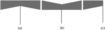
The main resonator constructed by arrangement of three similar sections, each of them works as a separate resonator and creates a specific transmission zero. The single CMRC cell, is the basic component of the main resonator, which shown in Fig. 1(a). The inverted CMRC and the half CMRC cells are also shown in Figs 1(b) and 1(c), respectively. These three sections are the building blocks of the main resonator. Propagation constant of a transmission line, is a function of distributed series inductances and shunt capacitances. Therefore, slow wave effect can be obtained, by increasing the value of capacitances and inductances of the transmission line. According to Fig. 1, in CMRC cells structure, narrow connecting lines and gaps between of these sections in the main resonator, result in inductance and capacitance values increment, respectively.
Building blocks structures of the main resonator, (a) single CMRC cell, (b) inverted CMRC cell, and (c) half CMRC cell.

The main resonator composed of three resonators with similar building block cells, as shown in Fig. 1. Therefore, if the dimensions of the single CMRC cell could be determined, the other parameters of the main resonator will be also obtained. The design procedure of obtaining geometrical parameters of the applied single CMRC is described in the following. Also, the effects of changing the geometrical parameters on the stopband and transmission zeros are studied in this section.
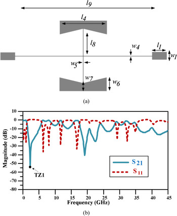
Two single CMRC elements are placed symmetrically in order to make resonator 1, as shown in Fig. 2(a). According to the mentioned substrate, dimensions of resonator 1 are as follows: l1 = 3 mm, l4 = 9.8 mm, l8 = 5.6 mm, l9 = 28.47 mm, w1 = 1.56 mm, w4 = w5 = 0.1 mm, w6 = 2.9 mm, and w7 = 1.7 mm. As seen in Fig. 2(b), the resonator 1 leads to sharp transition band about 0.81 GHz from −3 to −40 dB, which creates a transmission zero (TZ1) at 2.2 GHz with corresponding attenuation levels of −53.58 dB.
(a) Structure and (b) EM simulation results of the resonator 1.

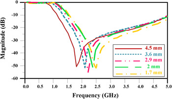
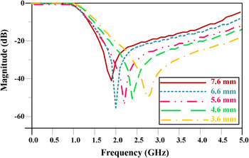
Created transmission zero of the resonator 1 (TZ1) is a function of w6, l4, and l8, as shown in Figs 3–5. The desired performance can be achieved, by adjusting the lengths of these parameters. Figure 3 shows the EM-simulated responses of S12 for the resonator 1, as function of w6. The location of the transmission zero (TZ1) could be changed, by adjusting the value of w6. According to Fig. 3, as the length of w6 increases, the stopband frequency moves to the lower frequencies. The results show that with the mentioned substrate, the best attenuation level for TZ1 could be achieved with w6 = 2.9 mm, which this value is chosen for resonator1.
EM-simulated response of S12 as function of w6 for resonator 1.

EM-simulated response of S12 as function of l4 for resonator 1.

EM-simulated response of S12 as function of l8 for resonator 1.

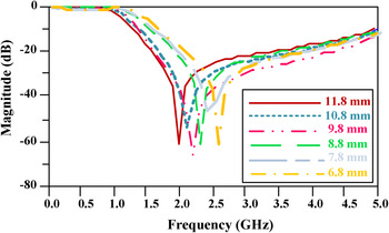
Figures 4 and 5 show the EM-simulated responses of S12 as function of l4 and l8 for the resonator 1, respectively. According to these figures, as the lengths of l4 and l8 increase, the stopband frequency moves to the lower frequencies. The location of the transmission zero (TZ1), also could be changed by adjusting the value of l4 and l8. The results show that, with l4 = 9.8 mm, the TZ1 has more attenuation level and the resonator 1 has the best performance.
The length of l8 has a significant effect on size of the main resonator, so the shorter length of l8 is more desirable. Also, due to fabrication limits, the length of l8 cannot be too small. As seen in Fig. 5, with l8 = 6.6 mm, the TZ1 has more attenuation level. But, on the other hand, to have a compact size, the best choice is l8 = 5.6 mm, which has good attenuation level and short size, simultaneously.
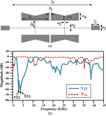
According to Fig. 1, after choosing the geometrical dimensions of the resonator 1, the geometrical dimensions of the other resonators will be simply obtained in the same way. Four inverted CMRC cells are placed symmetrically, in order to create resonator 2 as shown in Fig. 6(a). According to the mentioned substrate, dimensions of resonator 2 are as follows: l1 = 3 mm, l5 = 9.8 mm, l6 = 2.4 mm, l9 = 28.47 mm, w1 = 1.56 mm, w4 = w5 = 0.1 mm, w6 = 2.9 mm, w7 = 1.7 mm, and g1 = 0.2 mm. As seen in Fig. 6(b), resonator 2 creates two transmission zeros (TZ2 and TZ3) at 2.9 and 3.7 GHz with corresponding attenuation levels of −63.87 and −65.24 dB, respectively. Since TZ2 and TZ3 are located close to each other; a sharp transition band about 0.47 GHz from −3 to −40 dB is achieved.
(a) Structure, and (b) EM simulation results of the resonator 2.

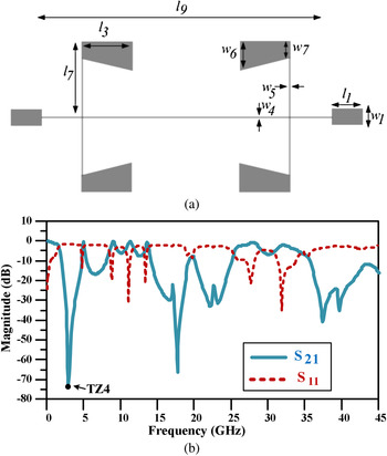
Four inverted half CMRC cells are placed symmetrically to make resonator 3, as shown in Fig. 7(a). According to the mentioned substrate, dimensions of resonator 3 are as follows: l1 = 3 mm, l3 = 4.9 mm, l7 = 7.3 mm, l9 = 28.47 mm, w1 = 1.56 mm, w4 = w5 = 0.1 mm, w6 = 2.9 mm, and w7 = 1.7 mm. As seen in Fig. 7(b), resonator 3 leads to a sharp transition band about 0.89 GHz from −3 to −40 dB. This resonator creates a transmission zero (TZ4) at 2.8 GHz with corresponding attenuation level of −73.36 dB.
(a) Structure, and (b) EM simulation results of the resonator 3.

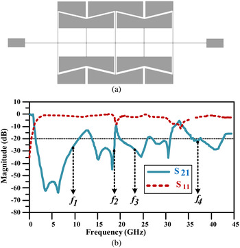
The main resonator is formed by using resonators 1, 2, and 3, as shown in Fig. 8(a). The frequency responses of the main resonator are shown in Fig. 8(b). The main resonator has a sharp transition band about 0.41 GHz from −3 to −40 dB and stopband 1.65–10.45 GHz with attenuation level higher than −20 dB. However, the stopband bandwidth is not wide enough. Therefore to achieve a wide stopband, the suppressing cells are used, which will be described in the next section.
(a) Structure, and (b) frequency responses of the main resonator.

III. PROPOSED FILTER DESIGN
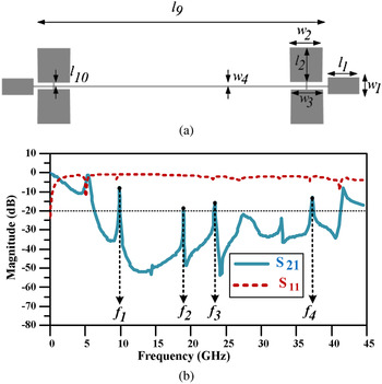
In design of the proposed filter, to increase the attenuation level in the stopband and also, to improve the stopband bandwidth, four suppressing cells are added to the proposed resonator. The structure of the suppressing cells is shown in Fig. 9(a). The dimensions of the suppressing cells are as follows: l1 = 3 mm, l2 = 3.35 mm, l9 = 28.47 mm, l10 = 0.22 mm, w1 = 1.56 mm, w2 = 3.1 mm, w3 = 3 mm, and w4 = 0.1 mm. As seen in Fig. 9(b), These suppressing cells can reject spurious frequencies between 6.1 to 41.2 GHz better than −20 dB except some narrowband regions with center frequencies of f1, f2, f3, and f4 (f1 = 9.7 GHz, f2 = 18.8 GHz, f3 = 23.2 GHz, and f4 = 36.9 GHz). These frequencies are suppressed by the main resonator as seen in Fig. 8(b). So in the proposed LPF, which composed of the main resonator and suppressing cells, these frequencies will be suppressed better than −20 dB.
(a) Structure, and (b) EM simulation results of the suppressing cells.

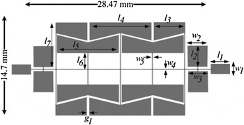
The structure of the proposed LPF is shown in Fig. 10. The dimensions of the proposed LPF are as follows: l1 = 3 mm, l2 = 3.35 mm, l3 = 4.9 mm, l4 = l5 = 9.8 mm, l6 = 2.5 mm, l7 = 7.3 mm, w1 = 1.56 mm, w2 = 3.1 mm, w3 = 3 mm, w4 = w5 = 0.1 mm, and g1 = 0.2 mm.
Structure of the proposed LPF.

IV. MEASURED AND SIMULATED RESULTS OF THE PROPOSED LPF
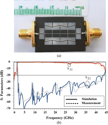
The photograph of the fabricated LPF is shown in Fig. 11(a). The S-parameters were measured using a HP8757A network analyzer. The measured and simulated results of the proposed LPF are shown in Fig. 11(b). As seen in this figure, the measured and simulated results are in good agreement. The proposed LPF has a −3 dB cut-off frequency at 1.5 GHz and it has extremely wide stopband from 1.68 to 44 GHz with attenuation level of higher than −20 dB. The overall size of the filter is 14.7 × 28.47 mm (0.1 λg × 0.19 λg), which shows excellent size reduction.
(a) Fabricated, (b) measurement, and simulation results of the proposed LPF.

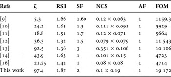
The performance comparison between the proposed LPF and previous related works is shown in the Table 1. In this table, the roll off rate (ζ) is calculated as follows:
 $$\zeta {\rm} = \displaystyle{{\alpha _{max} - \alpha _{min}} \over {f_s - f_c}}\; \,({\rm dB/GHz}),$$
where in (1) α max and α min are 40 and 3 dB attenuation points. f s and f c are 40 dB stop band (1.88 GHz) and the 3 dB cut-off (1.5 GHz) frequencies, respectively. The related stopband bandwidth (RSB) and suppression factor (SF), are given as:
 $$RSB{\rm} = \displaystyle{{stopband\; ( - 20\; \,{\rm dB)}} \over {stopband\; centre\; frequency}}, $$
 $$SF = \displaystyle{{rejection\; level\; in\; stopband\;} \over {10}}. $$
The proposed LPF has extremely wide stopband from 1.68 to 44 GHz, with attenuation level of higher than −20 dB, so according to (2) and (3) for the proposed LPF the SF is defined 2 and the RSB is equal to 1.87.
The performance comparison between the proposed LPF and previous related works.

The normalized circuit size (NCS) is defined as:
 $$NCS = \displaystyle{{physical\; size\; (length \times width)} \over {\lambda g^2}},$$
where λg is the guided wavelength. The architecture factor (AF) parameter is equal to 1 for two-dimensional (2D) circuits and equal to 2 for the 3D circuits. For the proposed LPF, the AF is defined as 1. The figure of merit (FOM) is calculated as follows:
 $$FOM{\rm} = \displaystyle{{\zeta \times RSB \times SF\; } \over {NCS \times AF}}.$$
According to Table 1, the proposed LPF shows the best performance, compared with reported works.
V. CONCLUSION
In this paper, a novel compact microstrip LPF with simple structure is designed, simulated and fabricated. The designed structure composed of four suppressing cells and main resonator, which consists of CMRC elements. The proposed LPF has sharp roll off and ultra wide stop band, which suppresses the 2nd to 29th harmonics with high attenuation level. There is good agreement between the simulated and measured results. The proposed LPF with such specifications can be used in modern communication systems.
ACKNOWLEDGEMENT
The authors would like to thank the Kermanshah Branch, Islamic Azad University for the financial support of this research project.
 Saeed Roshani received the B.Sc. degree in Electrical Engineering from Razi University, Kermanshah, Iran in 2008; M.Sc. degree in Electrical Engineering from Shahed University, Tehran, Iran in 2011; and Ph.D. in Electrical Engineering from Razi University in 2015. He performed opportunity research program in Amirkabir University of Technology (Tehran Polytechnics) Iran, in 2014–2015. He graduated as the best student of his country among all students of Iran on 2015 and Awarded by the First Vice President and Science, Research & Technology Minister. He is currently an Assistant Professor in the Department of Electrical Engineering at Islamic Azad University, Kermanshah, Iran. He has published more than 40 papers in ISI Journals and Conferences and two books. His research interest includes the microwave and millimeter wave devices and circuits, low-power and low-size integrated circuit design.