I. INTRODUCTION
Thermal energy can be converted into electrical current by means of the Seebeck effect. With suitable n- and p-doped materials and a temperature gradient, a voltage (i.e., an electric potential difference) can be created between the contacts on a thermoelectric device. For this, the n- and p-type thermoelectric materials must be thermally connected in parallel and electrically in series.Reference Rowe and Rowe1
Thermoelectric modules are used in a wide range of applications. One example is energy harvesting to supply ultralow-power devices.Reference Sommerlatte, Nielsch and Böttner2 Recent studies have demonstrated the potential for the use of thermoelectric modules in processes in which useful electrical energy can be generated through recovered waste heat.Reference Maranville, Schmitz and Jänsch3 Coupling of the thermoelectric materials with the heat generated by solar collectors is another application of thermoelectric modules.Reference Zebatjadi, Esfarjani, Dresselhaus, Ren and Chen4
The thermoelectric materials used until now can be categorized according to their application temperatures or material groups. Group V elements (Bi, Sb) and their alloys are suitable for low temperatures, whereas bismuth tellurides (Bi2Te3) and mixed crystals with compositions of Bi2Te3, Bi2Se3, and Sb2Te3 are the best choices at room temperature.Reference Sommerlatte, Nielsch and Böttner2,Reference Xi, Matijasevic, Ha, Baxter, Tritt, Kanatzidis, Mahan and Lyon5,Reference Lim, Whitacre, Fleurial, Huang, Ryan and Myung6 These materials are already commercially available, but their application temperature is limited up to 250 °C.
Lead tellurides as well as rare earth oxides and alloys of SiGe and FeSi2 are used at temperatures up to about 700 °C.Reference Noudem, Lemonnier, Prevel, Reddy, Guilmeau and Goupil7,Reference Jinushi, Okahara, Ishijima, Shikata, Kambe, Yoon, Kang, Eun and Kim8 Due to ecological concerns, the use of lead-containing materials must be minimized or completely eliminated through substitution by more environmentally friendly materials. Muta et al. present alkaline earth metal titanates as feasible alternatives.Reference Muta, Kirosaki and Yamanaka9,Reference Muta, Ieda, Kurosaki and Yamanaka10
The latest trends are pointing to the use of ceramic materials, especially for application temperatures above 700 °C. The suitability of a material for directly and efficiently converting heat energy into electrical current up to high temperatures is determined by its physical properties (Seebeck coefficient as well as electrical and thermal conductivities).
Therefore future solutions hinge on the development of thermoelectric materials of high long-term stability and efficiency. Suitable high-temperature contacts between thermoelectric module components are also of significance due to the dependency of the overall component efficiency on the joint quality. Ceramics, in particular, are very stable and reliable at higher temperatures. Since cobaltite has been found to be a promising ceramic for thermoelectrics, other ceramics like perovskites, ferrites, and titanium suboxides or boron carbides have also been investigated.Reference He, Hao, Chen, Poudel, Wang, Wang and Ren11,Reference Mori and Nishimura12 In this work, dedicated to the development of a suitable joining technology for the thermoelectric generator (TEG) modules, titanium suboxide and boron carbide ceramics have been used as thermoelectric materials.
Titanium suboxides (TiOx, x < 2) are n-type conductors. The thermoelectric properties of TiOx are highly dependent on the x values, which correlated to the change of crystal structures.Reference He, Hao, Chen, Poudel, Wang, Wang and Ren11 They are considered as candidates for thermoelectrics by a number of papers.Reference Backhaus-Ricoult, Rustad, Vargheese, Dutta and Work13,Reference Okinaka and Akiyama14 Titanium suboxides vary in a wide range of Ti:O ratios and so their electrical properties range from nearly metallic conduction up to poor semiconductivity.Reference Lee, Jeon, Kim, Choi and Yoo15 In the Ti–O binary system, interesting electrical properties were found in intermediate phases with x = 1.75–1.9 (Ref. Reference Bartholomew and Frankl16) and high Seebeck coefficients were shown in orthorhombic TiOx with x = 1.86–1.94.Reference Tsuyumoto, Hosono and Murata17 The maximal electrical conductivity is that of Ti4O7 with around 105 S/cm, but the Seebeck coefficient is rather low for this composition.Reference He, Hao, Chen, Poudel, Wang, Wang and Ren11,Reference Smith, Clarke and Walsh18 The thermal conductivity is in a reasonable range between 1 and 3 W/(m × K) for all titanium suboxides.Reference He, Hao, Chen, Poudel, Wang, Wang and Ren11 The challenge is to combine different suboxides in a way to maximize the resulting ZT (figure of merit).
Boron carbide ceramics are known to be p-type candidate materials for high-temperature thermoelectric energy (TE) conversion; in particular, boron-rich carbides (B4 + xC, 0 < x < 6.4) have shown promising TE properties such as a large Seebeck coefficient, moderate electrical conductivity, and relatively low thermal conductivity.Reference Werheit and Rogl19 The outstanding thermoelectric properties of boron carbides are considered to be related to their unique crystal structure.Reference Werheit and Tanaka20,Reference Amin21 As a single phase, boron carbides exhibit a wide homogeneity ranging from 8.8 at.% C (B10.4C) to 20 at.% C (B4C) and have rhombohedral elementary cells composed of 12-atom icosahedra and 3-atom chains.Reference Thevenot22,Reference Domnich, Reynaud, Haber and Chhowalla23 A high ZT value of 0.65 has been reported by Wood for a boron carbide with 10 at.% carbon and 0.5 at.% Mg addition at 1000 °C.Reference Wood and Emin24 However, one of the obstacles for its wide application is that a viable n-type boron carbide could not be found.Reference Rowe25
Thermoelectric applications generally require well matching p- and n-type legs. Titanium suboxide is a good n-type counterpart of boron carbide due to acceptable differences in its thermal expansion coefficient and excellent chemical stability at high temperatures.Reference Tsuyumoto, Hosono and Murata17 The proposed ZT values of TiOx are around 0.2 in most papers.
Current activities are focused on materials with suitable thermoelectric properties and on suitable joining technologies and material systems for contacting. The main requirement is that the TEG module components must be connected with good integrally bonded joints of low electrical and thermal resistance. In particular, these contacts must exhibit a low electrical resistance and hence have no negative impact on the overall module performance. Until now Cu, Ag, or Mo sheets have been used. Silver-containing pastes, in part with n-type powder or resin additives, have been used for producing the contacts between the n- and p-type legs.Reference Lim, Whitacre, Fleurial, Huang, Ryan and Myung6–Reference Jinushi, Okahara, Ishijima, Shikata, Kambe, Yoon, Kang, Eun and Kim8,Reference Funahashi, Urata, Mihara, Nabeshima and Iwasaki26 Comparative tests on producing contacts without the use of silver components proved unsuccessful, although the Cu electrode formed a molten phase at the joining temperature.Reference Jinushi, Okahara, Ishijima, Shikata, Kambe, Yoon, Kang, Eun and Kim8 Till date, furnace processes have been used consistently to achieve the temperature necessary for contacting.
Fernie et al. published a summary of filler systems for achieving integrally bonded joints between ceramic materials.Reference Fernie, Drew and Knowles27 Electrically conductive fillers are necessary to conduct the generated electrical energy. Therefore, metals or metal alloys are the first choice. Another general requirement is good wettability of the materials to be joined. Wetting of a solid by a liquid or melt is dependent on the chemical bonding of the two joining materials. Joining partners with similar chemical bonding exhibit wetting angles of θ < 90°, meaning that wetting is adequate. In most cases, however, the angle is much higher. This means that the wetting of the ceramics by metals is not sufficient for successful joining. This is due to the differences in the bonding electrons in ceramics (localized electrons) and metals (free electrons), making the metal-to-ceramic interface a discontinuity in the electron structure. The bond would merely be an adhesive bond. A chemical bond (reaction bond) can yield a joint strength that is 10–100 times higher than that of a pure adhesive bond.Reference Naidich28 Hence, reaction bonds are preferable. To enable these reactions to occur, small amounts of chemically active metals are added to the filler material.
For joining with the active filler, wetting of the ceramic surface is achieved by chemical interaction between the active component of the filler (e.g., Ti, Zr, Hf; Nb, Ta) and the interface and formation of a reaction zone. Thus, an integral joint is created between the filler matrix locally depleted of active metal and the ceramic material. For the active element to react successfully, it should not undergo prior oxidation.Reference Bach, Doege, Kutlu and Huskic29 Hence, joining is usually performed in vacuum (<10−5 mbar).
The present paper describes the development and testing of the laser-joining process, which creates new possibilities for producing high-efficiency TEGs for high-temperature applications (T > 1000 °C) using the advantages of laser-based brazing. The high localized joining temperatures achievable in extremely short times are characteristic of the laser process. This laser process has already been successfully tested in the production of gas-tight joints between various nonoxide (SiC, Si3N4) and oxide (Al2O3, ZrO2) ceramics.Reference Lippmann, Herrmann, Hille, Hurtado, Reinecke and Wolf30–Reference Börner, Lippmann and Hurtado32 Active noble metal-based fillers such as Ag–Cu fillers with or without additives (Ti, In, Zr, Hf) to improve wetting have been found to be ideal for ceramic joining.Reference Koppitz, Federmann, Reichle, Reisgen, Remmel and Zerfass33–Reference Klose35
For the active fillers, it has been shown that higher joining temperatures effect more pronounced diffusion and enrichment of the active component in the boundary layer to ceramics and hence an increase in joint strength. However, insufficient heating rates lead to partial evaporation of the silver due to its high vapor pressure.Reference Bach, Doege, Kutlu and Huskic29 Through optimization, the fast laser-joining process should prove superior to conventional furnace-based joining processes.
II. MATERIALS
Boron carbide with a superstoichiometric composition of B7C was synthesized using a mixture of commercial B4C powder (grade HD 20, d 50 = 0.5 μm, H. C. Starck, Germany) and amorphous boron (95 wt% purity, H. C. Starck, Germany). The powders were filled into a graphite die of 60 mm inner diameter lined with graphite foil. The graphite foil was coated with hBN suspension to prevent chemical reaction with the powder materials. In situ reactive fabrication of the sample was performed in a SPS apparatus (model HP d25/1, FCT Systeme GmbH, Germany) in argon atmosphere and 50 MPa at 1900 °C for 10 min; the heating rate was 100 K/min.
For preparation of titanium suboxide, TiO2 (99 wt% purity, Kronos, Crenox GmbH, Germany) and TiC (99 wt% purity, H. C. Starck, Germany) powders were used for the preparation of TiOx. The TiO2 and TiC powders were mixed in a first step to produce TiOx with x at about 1.8. The final TiOx powder was sintered by hot pressing (model HPW 315/400, FCT Systeme GmbH, Germany) at 1300 °C for 2 h with a pressure of 20 MPa in a graphite tool. The produced ceramic plate was sliced into the legs for the module fabrication finally.
Cu sheets were employed to achieve good heat transfer through the substrate to the n- and p-type legs. The Cu material used (Cu-OF from Allmeson GmbH) is oxygen free and is produced without the use of deoxidants. It possesses a high electrical conductivity and can be heat treated, welded, or brazed without the need for any special precautions. Machining and structuring of the individual traces and the connector tabs were performed with a CNC router (Fig. 1).
Model of CNC-structured Cu traces with recesses (a, module connector tab and b, structured trace for a pair of legs).

A Ti-containing Ag–Cu filler product (CB4 from Umicore AG & Co. KG, Germany), available as a normal commercial foil with a thickness of 100 µm, was selected for contacting the sheets with the substrate and legs. Experimental screening of various filler candidates was performed in advance to select the most suitable material.Reference Börner, Lippmann, Schreier, Hurtado, Hufenbach and Gude36
For the fabrication of the thermoelectric modules, a high dense aluminum nitride ceramic (AlN180, ANCeram, Germany) was used as the substrate material.
III. MODULE ASSEMBLY
The thermoelectric module consists of 7 p-type B7C and 7 n-type TiOx legs with dimensions of 5 mm × 5 mm × 4 mm, and the surface of the AlN substrate was 18 mm × 50 mm; after fabrication the total thickness of the module was 10 mm.
A schematic diagram illustrating the layout of a thermoelectric couple is given in Fig. 2.
Schematic diagram of a section through a pair of thermoelectric legs in a TEG module.
Module assembly was performed using the following steps. For placement of the n- and p-type legs, a positioning device with the exact substrate geometry was produced. Through holes were provided on the surface to insert the free legs. The legs were positioned in the holes with alternating n- and p-types. Appropriately cut filler foils were positioned to cover the top surfaces of the legs [Fig. 3(a)]. The layout of the copper sheets was done in a manner to ensure that these filler foils and the ends of the legs fit into the corresponding recesses (Fig. 3) in the copper sheets. For substrate contacting, additional filler foils were placed on the sheets [Fig. 3(b)], after which the substrate was laid on top to complete the module [Fig. 3(c)]. Single-sided, permanent contacting of the module components was done after the first laser process. After removal of the positioning device and repeating of the described assembly procedure on the opposite side, the second laser process took place, resulting in a completely assembled module with contacts [Fig. 3(d)]. The steps are illustrated in Fig. 3 below.
Schematic diagram for assembly steps for single board side (a, substrate with positioning device, legs, and filler foil; b, Cu sheets with filler foil; c, complete single board side assembly; and d, completed module with connector tabs).
IV. LASER JOINING
A diode laser (Rofin Sinar GmbH, Germany) with wave lengths 808 and 940 nm and a maximum power of 3.1 kW was used for laser joining of the ceramics. The laser beam was guided via a scanner after passing through a fixed optical element with focal length f = 405 mm. An elliptical figure was found to be the most suitable scan path and was adjusted according to the number of joined thermoelectric couples.
The partial transparency of the AlN substrate plate to the laser wave lengths was exploited to guide the laser beam. The transmittance of the AlN substrate was measured according to the principle of double integrating spheresReference Börner, Lippmann and Hurtado32 and was found to be 31.5% at a substrate height of 1.00 mm.
The laser-joining process can be described in the following way: the laser beam impinges on the substrate, is partially transmitted through the substrate plate, and is absorbed by the metal filler. This results in heating of the filler foils accompanied by a reduction in the thermal loading of the substrate. Laser irradiation must be performed in vacuum (Fig. 4) for two reasons: the TiOx component oxidizes in air at temperatures above 300 °C and additionally the Ti-active filler would oxidize quickly. Oxidation of the titanium suboxides would have an immediate effect on critical properties such as electrical and thermal conductivities. With respect to the Ti additive of the active filler, it is known that its main functions are to ensure good wetting of the ceramic and to enable chemical interaction at the filler–additive interface with the formation of a reaction layer. The chemical structure of this reaction layer significantly contributes to relieving the surface stresses in this region.Reference Naidich28 Because the active metal has a high reactivity, it must be ensured that it does not oxidize during the joining process and continues to be available for the formation of the joint.Reference Tillmann and Kollenberg37
Schematic diagram of test setup for laser-joining experiments.
Continuous laser irradiation during the joining process precluded the use of conventional methods such as thermocouples for localized temperature measurement. A temperature-measuring unit mounted right on the irradiated surface would also be irradiated and is not able to identify the correct temperature. Infrared thermography enables noncontact measurement of the surface temperature. In the laser process of the present study, an IR camera (VarioCam hr from Infratec GmbH, Germany) with a working range between 7.5 and 14.0 µm was used to record the temperature. To obtain realistic measurement signals, it is necessary to know the emission coefficients of the material to be measured. Emission coefficients of 0.82 and 0.91 were obtained for AlN and B4C, respectively. The measurement method for the determination of the material-specific emission coefficients is described exhaustively in Ref. Reference Börner, Lippmann and Hurtado32. Because the thermal imaging camera was positioned outside the vacuum chamber, the absorption of the ZnSe window in the vacuum chamber was also taken as a parameter and was adapted via the transmittance of the camera filter used (Fig. 4).
To optimize the laser process, it is important not only to concentrate on the temperature reached by the irradiated surface but also to consider the temperature distribution in the various layers. Because no direct measurements could be made on the various layers, the FEM-code COMSOL Multiphysics was used for calculating the temperature distribution. This program enabled additional equation systems and differential equations to be implemented and thermoelectric effects to be simulated.Reference Yushanov, Gritter, Crompton, Koppenhoefer and Sansone38
V. MODULE PERFORMANCE EVALUATION
The output voltage (U) and current (I) were measured using a module-testing device (Mtec01-600, TEC COM GmbH, Germany) in N2 atmosphere up to a temperature difference ΔT= 312 K, the hot-side temperature (T h) and cold-side temperature (T c) of the module were obtained by measuring the reference block temperatures at different positions. During testing, T c was adjusted with a heat exchanger and kept at T c < 65 °C. The output power (P) was calculated from the measured U and I; a schematic diagram of the module test apparatus is shown in Fig. 5.
Experimental assembly of module test apparatus for performance evaluation.
VI. RESULTS AND DISCUSSION
A. Optimization of laser-joining process
Single-sided joining of a module with 14 legs required a laser power density of maximum 3.34 W/mm2 and yielded AlN substrate surface temperatures reaching 900 °C. The laser power was increased in steps of 1% of the final power; after the required maximum power was reached (Fig. 6), the power was decreased in a controlled manner until the laser source was completely shut off. Under the ascertained optimum laser conditions, a uniform temperature distribution was recorded on the directly irradiated substrate surface. In contrast to previous studies,Reference Börner, Lippmann, Schreier, Hurtado, Hufenbach and Gude36 the current joining process involved an additional joint. With the introduction of the copper sheets, it became necessary to generate two seams (above and below the Cu component) in one laser irradiation step. In the design of the copper sheets, it had to be ensured that two lined-up joints could be produced during laser irradiation at a tolerable AlN substrate thermal load. Experimental investigations with copper sheets of varying height (0.5, 1.0, and 1.5 mm) yielded an optimum tape height of 1.0 mm.
TEG module at maximum joining temperature (a) and after joining and cooling (b).
The characteristic temperature profiles for the measuring points shown in Fig. 7 (P1–P4) on the AlN surface during laser treatment are given in Fig. 8.
Selection of measuring points.
Joining process temperature profiles.
Figure 8 shows curves of surface temperature versus time over the laser irradiation period. After rising steeply to approximately 900 °C the temperature dropped, despite the continuous increasing of the laser power. The recorded temperature drop can be explained by the melting of filler foil 1, leading to the transfer of heat to the conductive trace (due to the integrally bonded joint). This effect was simultaneously recorded as “heat loss” from the substrate surface by the IR camera. The resultant heating of the trace with further increasing of the laser power then led to the melting of filler foil 2 and hence to heat flow toward the ceramic legs.
This specific behavior during laser joining was observed in all joining tests. The temperature kinks visualized with the thermal imaging camera during joining can be helpful in controlling the laser-joining process.
The formation of bonds between the single layers induced by the heating of the different module layers by laser beam irradiation was simulated in the FEM-code COMSOL Multiphysics (COMSOL Multiphysics GmbH, Germany). Exemplary, Fig. 9 shows the separate phases from the simulation of the joining experiment in chronological order.
Simulated temperature distribution inside the separate layers of the module during joining process.
After exceeding the melting temperature of brazing foil 1 and melting of the solder (phase 1), the conductive path (copper sheets) is heated nearly up to the temperature of the AlN-substrate within seconds (phase 2). This causes the rise of the temperature of brazing foil 2 above the bars. The melting of the foil above the two bars happens in a time-delayed manner, because the different thermal conductivities of BxC and TiOx yield to different heat accumulations at the solder–ceramic junction. Only after the melting of brazing foil 2 (phase 3 and 4) does the full heating of the bars start. The thermal conductivities of the two materials are in this case essential for the rate of the heat transport. When the maximum laser beam power and temperature of the AlN-substrate surface (phase 5) is reached, the bars are completely through with heating and the brazing foils 1 and 2 exist as liquid phase. The shutdown of the laser beam (phase 6) causes a cooling of the components at different rates, depending on the heat capacities of the materials and the free surfaces for heat radiation exchange with the experiments performed via an infrared camera.
A comparison between the experimental and simulated surface substrate temperature can be seen in Fig. 10. In the phase of heating up (phase 1) until 460 s, there only exist marginal deviations between the simulated and the measured data (<5%). The melting point of brazing foil 1 is achieved 12 s earlier in the simulation than experimentally recorded via the infrared camera. The simulated course of temperature decrease after achieving the maximum laser beam power (t > 650 s) also conforms to the measured data.
Comparison of the substrate surface temperature between experiment and simulation.
Deviations of up to 8% between the simulation and the performed experiment exist in the range of the melting of brazing foil 2. The effect of temperature loss of the substrate during the melting of the braze, which can achieve up to 25 K, is not described completely in a realistic manner by the applied model. This is caused by the implementation of the melting and wettability behavior of the solder in the model. An abrupt change in the heat conductance between the single layers of the model can cause an out-of-memory error,Reference Poulain, Blanc, Kaminski, Semmache, Lemiti and Rao39 whereby no convergence could be achieved. However, the simulation provides a fine reproduction of the experimental data and reflects the chronological course of the melting processes for the single brazing foils well. The time gap between the melting of brazing foils 1 and 2 is 60 s in the simulation and 53 s in the related experiment, which displays a good conformance. The developed simulation model establishes the basis for calculating the temperature development inside the module during the laser-joining process in good approach. Advantages of the model are the possibilities of determining the temperature in defined positions of the TEG module during the joining process and to get information of potential overstressing inside the used materials.
B. Joint microstructure
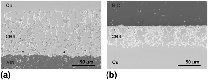
The individual joint quality is mainly determined by the properties of the interfaces between the filler and the ceramic material. Scanning electron microscope (SEM) investigations of the AlN substrate–Cu sheet–ceramic (p- and n-type) joints produced during the laser process showed joint seams that were continuous and free of macroscopic defects (e.g., air pockets, macrocracks). The active filler CB4 (70.5% Ag, 26.5% Cu, and 3% Ti) produced good joints with the ceramic materials (AlN, BxC, and TiOx) and the metal component (Cu) in the system. Micrographs of AlN–CB4–Cu and BxC–CB4–Cu at magnification 500x are given in Fig. 11 for illustration purposes.
Micrographs of joining plane for AlN–CB4–Cu (a) and Cu–CB4–BxC (b) (500x).
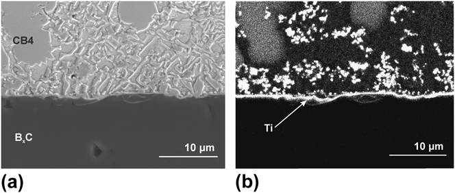
High-resolution ceramographic investigations of the filler–ceramic interfaces confirmed the formation of an intermediate layer during laser joining (Fig. 12). Formation of these reaction layers and their positive effects on the joint strength following conventional furnace joining have already been investigated and verified.Reference Naidich28 Analysis of the intermediate layer formed in the laser process also yielded a continuous Ti-enriched region along the filler–ceramic interface. Results of earlier work on laser joining using active fillers containing different amounts of Ti showed that the concentration of the deposited titanium in the interface region depended on the initial concentration in the active filler.Reference Klose35
SEM micrographs of CB4–B4C contact zone (a) and EDS-mapping investigation for titanium (b).
The Ti component was found to be enriched in the filler–ceramic interface region in all of the ceramics used (AlN, B4C, and TiOx) by EDS (energy-dispersive x-ray spectroscopy) analysis. As an example of this phenomenon, Fig. 12(b) shows the Ti enrichment in the CB4–BxC joint region.
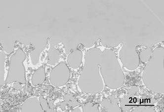
For the joint between filler CB4 and the Cu trace, diffusion of CB4 into the Cu matrix created an integrally bonded joint. As can be seen in Fig. 13, the Ag component (white in the image) penetrated into the Cu matrix and formed an alloy with Cu.
Microstructural formation in filler-trace joint region.
C. Strength
Four-point bending tests were performed on the ceramic–metal filler–ceramic joints in accordance with DIN 843-1 using butt-joined bars.40
Due to the special arrangement of the loading pins (Fig. 14), this method exclusively provided information about the joint strength. The laser-joined bars were positioned to ensure that the respective joint was centered between the pins.
Laser-joined bending bars.
Testing was done on a Zwick Roell machine by controlling the applied force (F max = 5 kN). Loading was selected to ensure that failure occurred no later than 15 s after the commencement of the test. The inner and outer spans were 20 and 40 mm, respectively.
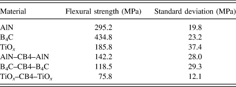
In the strength tests, all specimens broke in the joint regions. Failure in the region of the ceramic material was not observed in any tests. The respective strengths were calculated through averaging of the results of ten laser-joined samples. For comparison purposes, the strengths of compact specimens of the base materials AlN, TiOx, and B4C were obtained through averaging of five samples each (Table I).
Measured flexural strengths in four-point bending conditions.
The results yielded an adequate strength for the given application, with the TiOx–CB4–TiOx joint yielding the lowest value. The measured strength correlates well with the strength of the different monolithic materials. The current material development work is being dedicated to optimizing specific material properties.
D. Thermoelectric module tests
Figure 15 shows the output voltage V and power P as a function of current I of the module for various ΔT from 66 to 312 K. With increasing temperature difference the performance of the power generation increased constantly, the open voltage V op and the maximum output power P max reached 0.5 V and 75 mW at ΔT = 312 K, respectively. Since both boron carbide and titanium suboxide exhibit improved thermoelectric properties at high temperatures,Reference Amin21 better performance could be achieved by further increasing the temperature differences between both sides of the module. To investigate the durability and mechanical strength of the device, long-term stability experiments up to 100 repeating thermal cycles will be performed.
Output voltage (U) and power (P) as a function of current (I) of the module for ΔT = 66, 151, 233, and 312 K.
VII. CONCLUSIONS
During the development of TEGs consisting of ceramic materials, laser-induced brazing was successfully applied and tested as a technological option for joining and contacting the several components of TEG units. In this work, the self-developed ceramic BxC and TiOx as p- and n-type components and a commercial AlN substrate have been used. For joining and contacting of the components, an active brazing alloy on Ag–Cu-basis from the company Umicore Ltd. was chosen and tested. The laser-joined ceramic–metal bonds feature an adequate custom-designed strength (>75 MPa), are free of macroscopic faults, and show a homogenous structure. The creation of an enriched Ti-layer at the ceramic–metal bond was proved, although the laser joining requires only a very short process time when compared with a conventional furnace process. Such an enriched Ti-layer is crucial in increasing the bond strength of the joint.
By using the laser-joining technology it was possible to develop a technology for joining and contacting TEG units, which allow the use of a unitary filler system for all contact points and yields to a drastic abbreviation in process time. The realized measurements for power characterization of the modules could demonstrate the operational reliability of the produced brazing joints. The long-term behavior of these brazing bonds is currently investigated.
ACKNOWLEDGMENTS
The authors gratefully acknowledge the financial support from the European Union and the Free State of Saxony Grant No. SAB 13923/2379.