


1. Introduction
Power-assist mobile robots have received increasing attention as a practical means of reducing human physical workload during cooperative transportation tasks in indoor environments such as hospitals, warehouses, laboratories, and care facilities [Reference Sheridan1–Reference Solanes, Gracia, Munoz-Benavent, Miro, Carmichael and Tornero7]. While autonomous mobile robots are widely used for navigation and repetitive material-handling tasks in structured indoor environments, some transport scenarios still require direct human participation, intuitive maneuvering, and close physical cooperation. In such situations, fully autonomous operation may not always provide the flexibility and responsiveness needed for local transport assistance. From this perspective, human-intention-based power-assist robots may serve as a complementary solution for indoor cooperative transport [Reference Rozo, Bruno, Calinon and Caldwell4–Reference Solanes, Gracia, Munoz-Benavent, Miro, Carmichael and Tornero7]. In these structured settings, the robot is expected not only to provide locomotion support but also to respond in a natural manner to the user’s maneuvering intention during direct physical contact. This requirement has made physical human–robot interaction (pHRI) an important issue in the design of assistive mobile robotic systems [Reference Sheridan1–Reference Farajtabar and Charbonneau3, Reference Losey, McDonald, Battaglia and O’Malley8], since the quality of cooperation depends strongly on whether human input can be translated into intuitive and stable motion assistance. In particular, for indoor collaborative transport tasks involving repeated starts, stops, and directional changes in relatively constrained spaces, the robot should remain responsive to the user while maintaining safe and predictable motion behavior [Reference Rozo, Bruno, Calinon and Caldwell4–Reference Solanes, Gracia, Munoz-Benavent, Miro, Carmichael and Tornero7, Reference Aarno and Kragic9].
To achieve such behavior, previous studies have incorporated human-intention-aware assistance and compliance-based control strategies into assistive robotic systems [Reference Jain and Argall10–Reference Kelley, Tavakkoli, King, Nicolescu, Nicolescu and Bebis12]. Representative approaches include impedance- and admittance-based interaction control, shared-control frameworks, and motion-assist schemes that shape the robot response according to interaction-related cues [Reference Xing, Torabi, Ding, Gao, Deng, Mushahwar and Tavakoli5, Reference Ding, Xing, Torabi, Mehr, Sharifi, Gao, Mushahwar and Tavakoli6, Reference Losey, McDonald, Battaglia and O’Malley8, Reference Ott, Albu-Schaffer, Kugi and Hirzinger13–Reference Ye, Yang, Jiang and Zhang15]. These studies suggest that compliant motion generation is important for intuitive human–robot cooperation, since overly rigid or delayed responses may degrade maneuverability and increase user effort. For mobile assistive robots, this issue is particularly relevant in indoor applications, where the user typically expects the platform to follow intended forward (FW), backward (BW), and turning maneuvers without requiring cumbersome interfaces or explicit command inputs [Reference Aarno and Kragic9, Reference Jain and Argall10, Reference Kelley, Tavakkoli, King, Nicolescu, Nicolescu and Bebis12]. Accordingly, the ability to infer human intention and convert it into compliant robot motion may be regarded as an important requirement for practical power-assist systems [Reference Losey, McDonald, Battaglia and O’Malley8, Reference Jain and Argall10, Reference Zhang and Doyle11].
A major difficulty, however, is that human interaction intent is not directly observable in many practical platforms. Existing approaches often rely on dedicated force/torque sensors, handle-mounted sensing devices, or wearable sensing modalities such as bio-signals and inertial sensors in order to estimate user input [Reference Grosu, Grosu, Vanderborght, Lefeber and Rodriguez-Guerrero16–Reference Kumar and Pratihar19]. Although such methods can provide useful information, they may also increase hardware complexity, cost, calibration effort, and deployment constraints. In addition, direct reconstruction of human-applied force or moment from robot motion can be sensitive to model uncertainty, drivetrain friction, caster–ground interaction, floor unevenness, and numerical noise associated with differentiation. Consequently, the motion variation measured in an assistive mobile robot may reflect not only intentional human operation but also environmental disturbances and mechanical effects. This issue is particularly relevant in indoor differential-drive platforms with passive casters, where local floor conditions and caster-induced fluctuations may affect the measured motion response. From a control perspective, observer-based and disturbance-observer-based methods have been studied as effective tools for improving robustness against uncertainty and external perturbations [Reference Chen, Yang, Guo and Li20–Reference Bai, Zang, Wu, Li, Zhu and Zhao25], and related ideas have also been applied to mobile robotic systems subject to disturbance, skidding, slipping, and tracking uncertainty [Reference Chen26–Reference Wang and Zhai30]. Nevertheless, comparatively limited attention appears to have been given to sensorless frameworks that explicitly distinguish valid human interaction from disturbance-induced motion variations while maintaining an assistive control structure suitable for practical indoor mobile robots [Reference Han, Mao, Cao, Gan and Li22–Reference Bai, Zang, Wu, Li, Zhu and Zhao25].
From this viewpoint, the limitations of existing assistive-control schemes can be compared in terms of sensing requirements, user burden, disturbance ambiguity, and integration with assistive motion generation. Force/torque-sensor-based and wearable-sensor-based approaches can provide useful interaction or intent information, but they increase hardware complexity or user-dependent setup requirements. Meanwhile, observer-based sensorless estimation and mobile-robot disturbance-rejection methods reduce sensing requirements, but they do not necessarily distinguish intentional human interaction from disturbance-induced motion variations in cooperative transport tasks, particularly in indoor cooperative transport scenarios.
Conceptual illustration of the proposed human-intention-based power-assist robot.

Motivated by this issue, this paper proposes a sensorless human-intention-based control framework for a differential-drive power-assist mobile robot using only wheel-encoder measurements and motor-side actuation information, as illustrated in Figure 1. The proposed system is intended for human-in-the-loop cooperative transport rather than fully autonomous mobile operation. Instead of treating inverse dynamic reconstruction of human-applied force and moment as the final objective, the proposed method uses the nominal body-motion model as a physics-guided basis for intention estimation in the motion domain. Through this formulation, the framework is designed to support intention-consistent assistive control under practical indoor operating conditions, where direct interaction sensing is limited and observed motion may be influenced by environmental disturbances.
The main contributions of this study are summarized as follows:
-
• Sensorless motion-domain intention estimation: Unlike approaches centered on direct force reconstruction or dedicated interaction sensing, the proposed framework formulates human-intention estimation for power-assist mobile robots in the motion domain. This shifts the estimation target from force itself to interaction-consistent human-induced motion cues derived from encoder-based robot responses, which are more directly compatible with assistive motion generation.
-
• Disturbance-aware interaction separation: Although measured motion variations in indoor assistive mobile robots may contain both intentional human input and disturbance-induced effects, the proposed framework explicitly distinguishes these two components from interaction-sensitive robot responses. This provides a practically meaningful treatment of interaction ambiguity in differential-drive platforms subject to caster- and floor-related perturbations.
-
• Unified assistive control architecture: While previous studies have often addressed intention estimation, compliant control, and disturbance rejection as loosely connected elements, the proposed method integrates interaction observation, statistical human-intent validation, compliant motion generation, and disturbance compensation within a unified body-frame velocity-domain architecture. This integration establishes a systematic link between sensorless intention estimation and assistive control realization for indoor cooperative transport.
Table I summarizes the relationship between representative existing approaches and the proposed framework. The comparison highlights that the contribution of this study lies not only in reducing sensing requirements but also in integrating sensorless interaction-cue extraction, human-intent validation, compliant motion generation, and disturbance-aware compensation within a unified assistive-control architecture.
Through this design, the proposed system aims to provide intuitive assistive motion while reducing sensitivity to indoor environmental disturbances such as caster-induced fluctuations and floor-condition variations. The remainder of this paper is organized as follows. Section 2 describes the robot platform and its body-frame dynamic model. Section 3 presents the proposed methodology, including the interaction observer, human-intent analysis, virtual impedance-based compliant velocity generation, and disturbance-aware power-assist controller. Section 4 presents the experimental results for validating the effectiveness of the proposed framework. Finally, Section 5 concludes the paper.
2. System description
Figure 2 illustrates the conceptual hardware configuration of the proposed human-responsive power-assist mobile robot. The platform adopts a differential-drive structure consisting of two centrally located driving wheels actuated by DC motors with reduction gears, while passive casters are employed to support the chassis and maintain static stability. A rear-mounted handle provides the physical interface through which the user imposes translational and rotational intent during cooperative transport.
Comparison of representative assistive-control approaches and the proposed framework.

Table I. Long description
A table comparing assistive-control approaches and their advantages and limitations. The table has six rows and four columns. The columns are labeled Approach, Main sensing/estimation basis, Main advantage, and Limitation relative to this study. The rows are as follows: Row 1: Force/torque-sensor-based admittance or impedance control, Dedicated force/torque or handle-mounted sensors, Direct measurement of user interaction, Requires additional sensing hardware, calibration, and mechanical integration. Row 2: Wearable- or bio-signal-based intent recognition, EMG, IMU, or other wearable sensors, Provides user-motion or physiological intent information, Increases user burden and may require user-dependent setup. Row 3: Probabilistic or shared-control-based intent recognition, User-command history, robot state, or interaction-related cues, Enables intent-aware assistance or shared autonomy, Often focuses on intent inference without explicit disturbance separation. Row 4: Observer-based sensorless force or disturbance estimation, Encoder, motor-side information, and dynamic models, Reduces dependence on external interaction sensors, Estimated external input may contain both human intention and environmental disturbances. Row 5: Mobile-robot disturbance-rejection control, Disturbance observers or robust tracking controllers, Improves robustness to uncertain terrain, slip, or external perturbations, Usually focuses on tracking robustness rather than human-intent-consistent assistance. Row 6: Proposed framework, Wheel encoders and motor-side actuation information, Sensorless interaction-cue extraction, intent validation, compliant motion generation, and disturbance-aware compensation, Designed for structured indoor cooperative transport without dedicated force/torque sensing.
Hardware configuration and geometric variables of the proposed power-assist robot.

A key feature of the proposed platform is that it does not require dedicated force or torque sensors to measure the user input directly. Instead, the system relies on wheel-encoder measurements and motor-side actuation information to infer the user interaction intent in a sensorless manner. This configuration reduces hardware complexity and cost while preserving intuitive human–robot cooperative manipulation.
To describe the planar motion relevant to human–robot interaction, the robot motion is characterized by the body-frame longitudinal velocity
 $v$
and heading rate
 $\dot {\psi }$
. Let
 $\omega _L$
and
 $\omega _R$
denote the angular velocities of the left and right driving wheels, respectively,
 $r$
the wheel radius, and
 $2b$
the distance between the two driving wheels. Under the standard no-slip rolling assumption, the body-frame motion variables are given by
 \begin{equation} v = \frac {r}{2}(\omega _R+\omega _L), \qquad \dot {\psi } = \frac {r}{2b}(\omega _R-\omega _L), \end{equation}
implying that the translational and rotational motion of the robot can be reconstructed directly from wheel-encoder measurements.
In the implementation, the wheel angular velocities in Eq. (1) were obtained from incremental encoder counts. Let
 $c_i[k]$
denote the cumulative encoder count of the
 $i$
-th driving wheel at the
 $k$
-th sampling instant, where
 $i\in \{L,R\}$
. The count increment over one sampling period
 $T_s$
is
 $\Delta c_i[k]=c_i[k]-c_i[k-1]$
. Using the effective encoder resolution at the wheel output shaft,
 $N_{\mathrm{CPR}}=370$
counts/rev, the wheel angular velocity was calculated as
 \begin{equation} \omega _i[k] = \frac {2\pi }{N_{\mathrm{CPR}}T_s}\Delta c_i[k], \qquad i\in \{L,R\}. \end{equation}
The corresponding linear wheel velocity is
 $v_i[k]=r\omega _i[k]$
. Because
 $N_{\mathrm{CPR}}$
is defined at the wheel output shaft, the gear ratio is already reflected in the count-to-velocity conversion and is not applied separately.
For completeness, if a planar pose description is required, the robot pose can be written as
 \begin{equation} \boldsymbol{\eta }= \begin{bmatrix} x &\quad y &\quad \psi \end{bmatrix}^{\top}\!, \end{equation}
where
 $x$
and
 $y$
denote the planar position of the robot in a reference frame, and
 $\psi$
denotes the heading angle. The corresponding kinematic relation is given by
 \begin{equation} \, \dot{\kern-1pt x}=v\cos \psi ,\qquad \, \dot{\kern-1pt y}=v\sin \psi ,\qquad \dot {\psi }=\frac {r}{2b}(\omega _R-\omega _L). \end{equation}
However, in the present study, the primary variables of interest are the body-frame motion quantities in Eq. (1), since they directly reflect the motion response induced by human interaction and motor actuation.
To interpret the user contribution to the robot motion, a nominal dynamic model is introduced in the body frame. The robot body is modeled as a rigid planar system with total mass
 $m$
and yaw moment of inertia
 $J_z$
. Let
 $\tau _L$
and
 $\tau _R$
denote the motor torques applied to the left and right wheels, respectively. Under ideal rolling conditions, the net traction force generated by the two driving wheels and the yaw moment about the robot center are expressed as
 \begin{equation} F_t = \frac {\tau _L+\tau _R}{r}, \qquad M_t = \frac {b}{r}(\tau _R-\tau _L). \end{equation}
Let
 $F_{\mathrm{hum}}$
and
 $M_{\mathrm{hum}}$
denote the equivalent human-induced generalized force and generalized yaw moment acting on the robot in planar motion through the handle interaction. These equivalent inputs represent the net contribution of the handle-applied force, its point of application, and the associated geometric lever-arm effects with respect to the robot body center. In this study, such geometric effects are not modeled explicitly in three dimensions, but are absorbed into the equivalent planar interaction terms
 $F_{\mathrm{hum}}$
and
 $M_{\mathrm{hum}}$
. By incorporating lumped viscous resistance terms
 $c_v v$
and
 $c_{\psi }\dot {\psi }$
, the translational and rotational dynamics of the robot can be written as
 \begin{align} m\dot {v} = \frac {\tau _L+\tau _R}{r} + F_{\mathrm{hum}} - c_v v, \\[-12pt] \nonumber \end{align}
 \begin{align} J_z\ddot {\psi } = \frac {b}{r}(\tau _R-\tau _L) + M_{\mathrm{hum}} - c_{\psi }\dot {\psi }. \\[10pt] \nonumber\end{align}
For compact representation, the body-motion state and the human-interaction input are defined as
 \begin{equation} \mathbf{x}_{res}= \begin{bmatrix} v &\quad \dot {\psi } \end{bmatrix}^{\top}, \qquad \mathbf{f}_{\mathrm{hum}}= \begin{bmatrix} F_{\mathrm{hum}} &\quad M_{\mathrm{hum}} \end{bmatrix}^{\top}\!. \end{equation}
Then, the coupled translational and rotational dynamics can be rewritten in compact form as
 \begin{align} \dot {\mathbf{x}}_{res} = \mathbf{A}_v \mathbf{x}_{res} + \mathbf{B}_{\tau } \begin{bmatrix} \tau _L\\[3pt] \tau _R \end{bmatrix} + \mathbf{B}_h \mathbf{f}_{\mathrm{hum}}, \end{align}
where
 \begin{align} \mathbf{A}_v = \begin{bmatrix} -\dfrac {c_v}{m} &\quad 0\\[3pt] 0 &\quad -\dfrac {c_{\psi }}{J_z} \end{bmatrix}\!, \qquad \mathbf{B}_{\tau } = \begin{bmatrix} \dfrac {1}{mr} &\quad \dfrac {1}{mr}\\[8pt] -\dfrac {b}{J_z r} &\quad \dfrac {b}{J_z r} \end{bmatrix}\!, \qquad \mathbf{B}_h = \begin{bmatrix} \dfrac {1}{m} &\quad 0\\[3pt] 0 &\quad \dfrac {1}{J_z} \end{bmatrix}\!. \end{align}
The dynamic model in Eq. (9) provides a physical interpretation of how human interaction is embedded in the measured wheel motion and motor actuation. In particular, under ideal modeling assumptions, the equivalent human-induced generalized force and generalized yaw moment can be interpreted through the inverse relations
 \begin{align} F_{\mathrm{hum}} = m\dot {v} - \frac {\tau _L+\tau _R}{r} + c_v v, \\[-12pt] \nonumber \end{align}
 \begin{align} M_{\mathrm{hum}} = J_z\ddot {\psi } - \frac {b}{r}(\tau _R-\tau _L) + c_{\psi }\dot {\psi }. \\[10pt] \nonumber \end{align}
These relations provide a physics-based interpretation of the human interaction embedded in encoder-derived motion variables and motor-side actuation.
3. Methodology
3.1. Overview
Building upon the nominal body-frame model introduced in Section 2, the proposed methodology is designed to estimate human-intent variables in the translational and rotational directions, rather than to directly reconstruct the human-applied force and moment as the final output. Although Eqs. (11) and (12) provide a useful physics-based interpretation of how human interaction is reflected in encoder-derived motion variables, explicit inverse dynamics is sensitive to drivetrain friction, caster–ground interaction, parameter uncertainty, unmodeled disturbances, and numerical noise caused by differentiation. Therefore, the proposed framework uses the nominal model only as a physics-guided basis for sensorless intention estimation.
Figure 3 presents the overall control architecture of the proposed sensorless assistive robot. The measured robot motion state
 $\mathbf{x}_{res}$
is first processed by an interaction observer to extract interaction-sensitive information related to external inputs. The resulting interaction-related estimate is then provided to the human-intent analysis module, where it is combined with encoder-derived motion features to distinguish intentional human input from environmental disturbances and to generate the corresponding human-induced and disturbance-induced acceleration variables, denoted by
 $\widehat {\dot {\mathbf{x}}}_{\mathrm{hum}}$
and
 $\widehat {\dot {\mathbf{x}}}_{\mathrm{dis}}$
, respectively. The estimated human-induced component is subsequently transformed by the virtual impedance model (VIM) into a compliant velocity command
 $\mathbf{x}_c$
, whereas the disturbance-induced component is routed to the disturbance-cue path for disturbance rejection in the subsequent control stage. The power-assist controller then integrates these signals to generate the reference velocity command
 $\mathbf{x}_{ref}$
for the robot. The observer design, the human-intent analysis process, and the assistive control strategy are described in the following subsections.
Block diagram of the proposed human-intention-based control framework.

3.2. Interaction observer
The proposed interaction observer is designed to extract an acceleration-domain interaction cue from the discrepancy between the commanded motion variation and the measured robot response, without relying on dedicated force or torque sensors. In the closed-loop velocity control structure, the commanded velocity is generally tracked during steady motion, so the residual interaction information is primarily reflected in transient motion variations caused by human maneuvers or external disturbances. For this reason, the observer is formulated in the acceleration domain so as to emphasize motion-transition components while reducing the influence of steady-state velocity tracking.
Let the commanded body-frame velocity state be defined as
 \begin{equation} \mathbf{x}_{ref}(t)= \begin{bmatrix} v_{ref}(t) &\quad \dot {\psi }_{ref}(t) \end{bmatrix}^{\top}\!, \end{equation}
and let the measured robot velocity state
 $\mathbf{x}_{res}(t)$
follow the definition introduced in Section 2. The corresponding commanded motion variation is represented by
 \begin{equation} \dot {\mathbf{x}}_{ref}(t)= \begin{bmatrix} \dot {v}_{ref}(t) &\quad \ddot {\psi }_{ref}(t) \end{bmatrix}^{\top}\!. \end{equation}
No additional smoothing was applied directly to the encoder count increments before the wheel-velocity conversion. Instead, encoder-induced high-frequency fluctuations in the acceleration-domain residual are attenuated by the low-pass filtering operation in Eq. (16).
The acceleration-domain residual is then defined as
 \begin{equation} \mathbf{e}_a(t) = \dot {\mathbf{x}}_{ref}(t)-\dot {\mathbf{x}}_{res}(t), \end{equation}
where
 $\dot {\mathbf{x}}_{res}(t)$
is obtained from the encoder-derived body-frame velocity signals through numerical differentiation. Since direct differentiation of encoder signals may amplify quantization effects and measurement noise,
 $\dot {\mathbf{x}}_{res}(t)$
is interpreted here as a measured motion-variation cue rather than an exact physical acceleration.
To suppress encoder-induced high-frequency fluctuations while retaining the dominant interaction-related variation, a low-pass filtered residual state,
 \begin{equation} \boldsymbol{\xi }(t)= \begin{bmatrix} \xi _v(t) &\quad \xi _{\psi }(t) \end{bmatrix}^{\top}\!, \end{equation}
is introduced as
 \begin{equation} \dot {\boldsymbol{\xi }}(t) = -\boldsymbol{\Lambda}\boldsymbol{\xi }(t) + \boldsymbol{\Lambda }\mathbf{e}_a(t), \end{equation}
where
 \begin{align} \boldsymbol{\Lambda }= \begin{bmatrix} \lambda _1 &\quad 0\\[3pt] 0 &\quad \lambda _2 \end{bmatrix} \end{align}
is a diagonal matrix of low-pass filter gains for the translational and rotational channels.
Using this filtered acceleration residual, the observer output is defined as
 \begin{equation} \mathbf{z}_{obs}(t) = \mathbf{G}_o \boldsymbol{\xi }(t), \end{equation}
where
 \begin{align} \mathbf{G}_o= \begin{bmatrix} g_{o1} &\quad 0\\[3pt] 0 &\quad g_{o2} \end{bmatrix} \end{align}
is the observer gain matrix. Here,
 $\boldsymbol{\xi }(t)$
represents the dominant low-frequency component of the acceleration mismatch between the commanded motion variation and the measured robot response, while
 $\mathbf{G}_o$
scales this quantity into an interaction-sensitive cue in the translational and rotational directions.
Accordingly, the observer output can be interpreted as
 \begin{equation} \mathbf{z}_{obs}(t)\sim \begin{bmatrix} \widehat {\dot {v}}_{obs}(t) &\quad \widehat {\ddot {\psi }}_{obs}(t) \end{bmatrix}^{\top}\!, \end{equation}
which reflects the combined effect of human-induced and disturbance-induced motion variations observed during transient robot motion. Therefore,
 $\mathbf{z}_{obs}(t)$
is not regarded as the final estimate of human intention by itself; rather, it serves as an intermediate interaction-sensitive representation that is further processed by the subsequent human-intent analysis and disturbance-cue generation modules.
3.3. Human-intent analysis
The purpose of this stage is to identify the human-induced component of the observer output while rejecting motion variations caused by environmental disturbances. Rather than directly reconstructing the human-applied force as the final output, the proposed method determines whether the observed interaction pattern is consistent with representative human operation and then extracts the corresponding human-induced acceleration component. Signals that fail to exhibit sufficient consistency with valid human-interaction patterns are not accepted as human-intent-related components and are instead interpreted as disturbance-related variations.
3.3.1. Feature selection and statistical definition of human intent
To establish a statistical description of representative human interaction patterns, interaction data were collected for each motion category under repeated human operation. In particular, 100 signal samples were acquired for each representative interaction class. The collected dataset was then analyzed to determine which signal characteristics most effectively distinguish intentional human operation from other motion variations.
Candidate signal descriptors were first examined through comparative visualization of the collected interaction data. As illustrated in Figure 4, the initial candidate features were amplitude, rise time, fall time, total duration, and the speed difference between the two wheels. These features were selected on the premise that human interaction patterns are inherently multi-dimensional: the magnitude of the signal reflects interaction intensity, the rise and fall times describe transient behavior, the total duration represents persistence, and the wheel-speed difference captures directional asymmetry in the robot response.
Example of features extracted from encoder-derived acceleration for human-intent recognition.

Figure 4. Long description
The image contains two line graphs. Panel A: The first line graph shows encoder-derived acceleration over time. The x-axis represents time in seconds, ranging from 0 to 7 seconds. The y-axis represents acceleration in unspecified units, ranging from -0.5 to 2. The graph includes multiple colored lines and annotations indicating specific points and values. Notable features include a peak labeled A, a blue horizontal line labeled T, a magenta horizontal line labeled T, and a green horizontal line labeled Td. Panel B: The second line graph displays left and right wheel velocity and velocity difference over time. The x-axis represents time in seconds, ranging from 0 to 10 seconds. The y-axis represents velocity in unspecified units, ranging from -2 to 2. The graph includes three lines: a blue line representing left wheel velocity (vL), a red line representing right wheel velocity (vR), and a dashed black line representing velocity difference (Δv). A yellow dot highlights a specific point on the graph labeled Δv.
Accordingly, reliable discrimination of human intent requires the combined use of temporal and kinematic features rather than reliance on any single descriptor. Based on this rationale, the encoder-derived feature vector is defined as
 \begin{equation} \boldsymbol{\phi }(t)= \begin{bmatrix} A(t) &\quad T_r(t) &\quad T_f(t) &\quad T_d(t) &\quad \Delta v(t) \end{bmatrix}^{\top}\!, \end{equation}
where
 $A(t)$
,
 $T_r(t)$
,
 $T_f(t)$
, and
 $T_d(t)$
are the amplitude, rise time, fall time, and total duration of the encoder-derived acceleration, respectively, and
 $\Delta v(t)$
is the signed wheel-speed difference defined as
 \begin{equation} \Delta v(t)=v_L(t)-v_R(t), \end{equation}
where
 $v_L(t)$
and
 $v_R(t)$
denote the linear velocities of the left and right driving wheels, respectively. With this convention,
 $\Delta v(t)\gt 0$
represents a left-turn (LT) tendency, whereas
 $\Delta v(t)\lt 0$
represents a right-turn (RT) tendency. Therefore, the sign of
 $\Delta v(t)$
provides directional information for distinguishing the turning direction, while the amplitude and temporal features describe the transient characteristics of the interaction event.
The collected human interaction patterns were then organized into the following eight classes:
 \begin{align} \begin{aligned} \mathcal{C}=\{ &\mathrm{FW},\, {\mathrm{FW}_{\mathrm{STOP}}},\, \mathrm{BW},\, {\mathrm{BW}_{\mathrm{STOP}}},\, \mathrm{LT},\, {\mathrm{LT}_{\mathrm{STOP}}},\, \mathrm{RT},\, {\mathrm{RT}_{\mathrm{STOP}}} \}. \end{aligned} \end{align}
These classes correspond to FW, BW, LT, RT, and their associated stopping interactions. The signed definition of
 $\Delta v(t)$
in Eq. (23) is used consistently for both continuous turning classes, LT and RT, and their corresponding stopping-transition classes, LTSTOP and RTSTOP. Representative examples of the classified interaction patterns are shown in Figure 5.
To evaluate the separability of the candidate features, the distributions of the collected data were first inspected using bar plots and box plots. As shown in Table II and Figure 6, the selected features exhibit class-dependent tendencies in amplitude, duration, rise time, fall time, and wheel-speed difference, although partial overlap remains among some classes. These results indicate that the proposed features provide complementary descriptive information for human-intent characterization.
Mean and standard deviation of extracted features across eight intent classes.

Table II. Long description
A table comparing mean and standard deviation of extracted features across eight intent classes. The table has eight rows and five columns. The columns are labeled A, Tr, Tf, Td, and |Δv|. The rows are labeled with the classes FW, FW_stop, BW, BW_stop, LT, LT_stop, RT, and RT_stop. Each cell contains a mean value and a standard deviation. Row 1: FW, A: 1.320 ± 0.183, Tr: 0.280 ± 0.094, Tf: 0.778 ± 0.163, Td: 1.058 ± 0.155, |Δv|: 0.035 ± 0.022. Row 2: FW_stop, A: -1.237 ± 0.153, Tr: 0.728 ± 0.212, Tf: 0.479 ± 0.116, Td: 1.206 ± 0.221, |Δv|: 0.038 ± 0.021. Row 3: BW, A: -1.212 ± 0.143, Tr: 0.221 ± 0.101, Tf: 0.603 ± 0.187, Td: 0.823 ± 0.203, |Δv|: 0.070 ± 0.024. Row 4: BW_stop, A: 1.360 ± 0.165, Tr: 0.581 ± 0.148, Tf: 0.424 ± 0.096, Td: 1.006 ± 0.142, |Δv|: 0.019 ± 0.016. Row 5: LT, A: 0.593 ± 0.137, Tr: 0.558 ± 0.433, Tf: 0.868 ± 0.488, Td: 1.426 ± 0.489, |Δv|: 0.372 ± 0.091. Row 6: LT_stop, A: -0.776 ± 0.138, Tr: 0.614 ± 0.217, Tf: 0.634 ± 0.146, Td: 1.248 ± 0.259, |Δv|: 0.304 ± 0.049. Row 7: RT, A: -0.848 ± 0.321, Tr: 0.410 ± 0.228, Tf: 0.613 ± 0.359, Td: 1.023 ± 0.388, |Δv|: 0.379 ± 0.081. Row 8: RT_stop, A: 0.732 ± 0.169, Tr: 0.539 ± 0.233, Tf: 0.650 ± 0.168, Td: 1.188 ± 0.283, |Δv|: 0.289 ± 0.041.
Representative Encoder-derived translational and angular accelerations for motion and stop intent classes.

Box plots of the extracted features across eight intent classes.

To further examine the feature-space structure, both linear and nonlinear embedding analyses were performed, as shown in Figure 7(a) and (b). The PCA projection in Figure 7(a) shows partial overlap among several classes in the three-dimensional linear subspace. This overlap can be partly attributed to the nature of PCA, which preserves the dominant directions of global variance rather than directions optimized for class discrimination. Accordingly, class-dependent information contained in the original five-dimensional feature vector may be compressed or mixed when projected onto the first three principal components.
By contrast, the t-SNE projection in Figure 7(b) shows more compact local groupings for several classes. This result suggests that the selected features contain local neighborhood structure associated with the interaction classes, although the projection itself does not provide a quantitative classification criterion. Because t-SNE is a nonlinear visualization method, the observed grouping pattern should be regarded as qualitative evidence of feature-space organization rather than as a direct decision boundary.
Overall, Figure 7 indicates that the extracted features exhibit class-dependent tendencies in low-dimensional visualizations, while also showing that the degree of separation depends on the projection method. Therefore, the PCA and t-SNE results are used here as supplementary visual evidence for feature characterization, rather than as a substitute for the subsequent quantitative classification analysis.
Low-dimensional projections of encoder-derived features across eight human-intent classes.

3.3.2. MVN-based classifier using Mahalanobis distance
Based on the separability analysis, an MVN-based class-wise probabilistic model is adopted for human-intent classification. This formulation is well suited to the selected low-dimensional feature space, where each human-interaction class can be compactly represented by its mean vector and covariance structure. Under this formulation, the Mahalanobis distance provides a natural decision metric by measuring the consistency of an input feature vector with each class while accounting for class-dependent variance and feature correlation.
The MVN parameters were estimated using the five-dimensional feature samples defined in Eq. (22). Before class-wise parameter estimation, the feature vectors were standardized to reduce scale differences among the amplitude, temporal, and wheel-speed-difference features. Let
 $\boldsymbol{\phi }_i\in \mathbb{R}^{5}$
denote the raw feature vector of the
 $i$
-th event sample, following the feature order in Eq. (22). Before estimating the MVN parameters, the feature vectors were standardized by z-score normalization:
 \begin{equation} \,\bar {\boldsymbol{ \kern-2pt \phi }}_i = \frac {\boldsymbol{\phi }_i-\boldsymbol{\mu }_z}{\boldsymbol{\sigma }_z}, \end{equation}
where
 $\boldsymbol{\mu }_z$
and
 $\boldsymbol{\sigma }_z$
denote the mean and standard deviation vectors computed from the feature samples used for MVN parameter estimation. This normalization reduces scale differences among the amplitude, temporal, and wheel-speed-difference features.
For each class
 $k\in \mathcal{C}$
, the class mean vector and covariance matrix were estimated from the normalized feature samples as
 \begin{equation} \boldsymbol{\mu }_k = \frac {1}{n_k} \sum _{i\in \mathcal{I}_k} \,\bar {\boldsymbol{ \kern-2pt \phi }}_i, \end{equation}
and
 \begin{equation} \mathbf{\Sigma }_k = \frac {1}{n_k-1} \sum _{i\in \mathcal{I}_k} \left ( \,\bar {\boldsymbol{ \kern-2pt \phi }}_i-\boldsymbol{\mu }_k \right ) \left ( \,\bar {\boldsymbol{ \kern-2pt \phi }}_i-\boldsymbol{\mu }_k \right )^{\top}\!, \end{equation}
where
 $\mathcal{I}_k$
is the index set of samples belonging to class
 $k$
, and
 $n_k$
is the number of samples in that class. For numerical stability, the covariance matrix was symmetrized and regularized as
 \begin{equation} \mathbf{\Sigma }_k \leftarrow \frac {\mathbf{\Sigma }_k+\mathbf{\Sigma }_k^{\top}}{2} + \epsilon _{\mathrm{reg}}\mathbf{I}, \qquad \epsilon _{\mathrm{reg}}=10^{-6}. \end{equation}
The small Tikhonov regularization term was fixed for all classes and was used only to avoid numerical singularity in covariance inversion.
For the
 $k$
-th class, the class-conditional distribution in the normalized feature space is written as
 \begin{equation} p(\,\bar {\boldsymbol{ \kern-2pt \phi }}\mid k) = \mathcal{N} \left ( \boldsymbol{\mu }_k,\mathbf{\Sigma }_k \right ), \qquad k\in \mathcal{C}. \end{equation}
Given an incoming feature vector
 $\boldsymbol{\phi }(t)$
, the same z-score normalization in Eq. (25) is first applied to obtain
 $\,\bar {\boldsymbol{ \kern-2pt \phi }}(t)$
. The Mahalanobis distance to the
 $k$
-th class is then defined as
 \begin{equation} d_k^2(t) = \left ( \,\bar {\boldsymbol{ \kern-2pt \phi }}(t)-\boldsymbol{\mu }_k \right )^{\top} \mathbf{\Sigma }_k^{-1} \left ( \,\bar {\boldsymbol{ \kern-2pt \phi }}(t)-\boldsymbol{\mu }_k \right)\!. \end{equation}
This distance measures the consistency of the incoming feature vector with each class while accounting for class-dependent variance and feature correlation. The most likely class is then selected as
 \begin{equation} k^{\ast }(t)=\arg \min _{k\in \mathcal{C}} d_k^2(t). \end{equation}
The class-acceptance threshold
 $\gamma$
was determined from the feature dimension rather than by manual tuning. Under the class-conditional Gaussian assumption, the squared Mahalanobis distance of a five-dimensional feature vector follows a chi-square distribution with five degrees of freedom. Accordingly, the inlier threshold was set to the 99% confidence boundary:
 \begin{equation} \gamma = \chi ^2_{5}(0.99) = 15.086. \end{equation}
This value corresponds to a nominal 1% false-rejection probability for true inlier samples under the Gaussian assumption. In addition to time-domain feature similarity, valid human-interaction signals are assumed to be concentrated mainly in the low-frequency range, with negligible high-frequency content above 1 Hz. Therefore, two frequency-domain thresholds,
 $\epsilon _1$
and
 $\epsilon _2$
, were used as additional frequency-consistency gates. While
 $\gamma$
evaluates the consistency of a feature vector with the class-wise MVN distributions,
 $\epsilon _1$
and
 $\epsilon _2$
suppress disturbance-like signals that contain relatively strong high- or mid-frequency components. In this study,
 $\epsilon _1=0.12$
and
 $\epsilon _2=0.30$
were fixed throughout the classification and transportation experiments after preliminary inspection of the collected representative interaction and disturbance-related signals. Accordingly, a candidate interaction is accepted as valid human intent only when both the class-membership condition and the frequency-consistency condition are satisfied:
 \begin{align} \Gamma _{hum}(t) &= \big (d_{k^{\ast }}^2(t)\le \gamma \big ) \land (E_{\gt 1\mathrm{Hz}}(t)\le \epsilon _{1} ) \land (E_{0.3 - 1\mathrm{Hz}}(t)\le \epsilon _{2} ), \nonumber\\[4pt] q_{hum}(t) &= \begin{cases} 1, &\ \text{if } \Gamma _{hum}(t),\\[3pt] 0, &\ \text{otherwise}. \end{cases}\end{align}
where
 $\Gamma _{hum}(t)$
denotes the combined human-intent acceptance condition,
 $q_{hum}(t)$
is the resulting binary validity flag.
For the classification-performance evaluation reported in Section 4, the data were divided using a file-level 60/40 split: 60% of the recording files were used for MVN parameter estimation, and the remaining 40% were used as the held-out test set. The same file-level split was applied to the encoder-derived translational- and angular-acceleration datasets to maintain consistency between translational and rotational intent classes. For online use, the estimated normalization statistics, class-wise MVN parameters, and threshold values were fixed and used in the inlier-checking routine.
3.3.3. Human and disturbance acceleration outputs
The observer output
 $\mathbf{z}_{obs}(t)$
contains the combined effect of human-induced and disturbance-induced motion variations. Once the observed interaction is classified as a valid human-intent pattern, the human-induced acceleration component is extracted by gating the observer output with the decision variable in Eq. (33):
 \begin{equation} \widehat {\dot {\mathbf{x}}}_{hum}(t) = q_{hum}(t)\,\mathbf{z}_{obs}(t). \end{equation}
Accordingly, the disturbance-related acceleration component is defined as the residual part of the observer output:
 \begin{equation} \widehat {\dot {\mathbf{x}}}_{dis}(t) = \mathbf{z}_{obs}(t)-\widehat {\dot {\mathbf{x}}}_{hum}(t). \end{equation}
Here,
 \begin{equation} \widehat {\dot {\mathbf{x}}}_{hum}(t) = \begin{bmatrix} \widehat {\dot {v}}_{hum}(t) &\quad \widehat {\ddot {\psi }}_{hum}(t) \end{bmatrix}^{\top}\!, \quad \widehat {\dot {\mathbf{x}}}_{dis}(t) = \begin{bmatrix} \widehat {\dot {v}}_{dis}(t) &\quad \widehat {\ddot {\psi }}_{dis}(t) \end{bmatrix}^{\top}\!. \end{equation}
Therefore, this stage provides two outputs consistent with the overall control architecture in Figure 3: the estimated human-induced acceleration
 $\widehat {\dot {\mathbf{x}}}_{hum}(t)$
, which is supplied to the VIM, and the estimated disturbance-induced acceleration
 $\widehat {\dot {\mathbf{x}}}_{dis}(t)$
, which is supplied to the disturbance-cue path for disturbance rejection in the subsequent control stage.
3.4. Virtual impedance-based compliant velocity generation
As described in Section 2, the robot motion relevant to human–robot interaction is represented in the body frame by the velocity state
 $\mathbf{x}_{res}(t)$
. Accordingly, the assistive motion is also generated in the same body-frame velocity coordinates so that it can be directly incorporated into the subsequent control law. Rather than explicitly reconstructing the equivalent human generalized force in Eqs. (11) and (12), the proposed method uses the estimated human-induced acceleration as a motion-domain interaction cue and transforms it into a compliant velocity command through a VIM.
The human-intent analysis stage yields the estimated human-induced acceleration
 $\widehat {\dot {\mathbf{x}}}_{hum}(t)$
, which represents the intentional motion-inducing component embedded in the robot response. The compliant velocity state generated by the VIM is defined as
 \begin{equation} \mathbf{x}_c(t) = \begin{bmatrix} v_c(t) &\quad \dot {\psi }_c(t) \end{bmatrix}^{\top}, \end{equation}
where
 $v_c(t)$
and
 $\dot {\psi }_c(t)$
denote the compliant translational and rotational velocity commands, respectively. Since
 $\mathbf{x}_c(t)$
is defined in the same body-frame velocity coordinates as
 $\mathbf{x}_{res}(t)$
, it is compatible with the nominal robot model and can be directly used in the subsequent assistive control stage.
The VIM is first defined in an impedance form as
 \begin{equation} \mathbf{M}_c \dot {\mathbf{x}}_c(t) + \mathbf{D}_c \mathbf{x}_c(t) = \mathbf{K}_c \widehat {\dot {\mathbf{x}}}_{hum}(t), \end{equation}
where
 $\mathbf{M}_c \in \mathbb{R}^{2\times 2}$
,
 $\mathbf{D}_c \in \mathbb{R}^{2\times 2}$
, and
 $\mathbf{K}_c \in \mathbb{R}^{2\times 2}$
denote the virtual inertia, damping, and input scaling matrices, respectively. These matrices are not physical parameters of the actual robot in Eq. (9), but virtual design parameters used to shape the compliant assistive response.
By rearranging Eq. (38), the compliant velocity dynamics can be written as
 \begin{equation} \dot {\mathbf{x}}_c(t) = \mathbf{M}_c^{-1} \left ( \mathbf{K}_c \widehat {\dot {\mathbf{x}}}_{hum}(t) - \mathbf{D}_c \mathbf{x}_c(t) \right )\!. \end{equation}
Defining
 \begin{equation} \mathbf{A}_c = -\mathbf{M}_c^{-1}\mathbf{D}_c, \quad \mathbf{B}_c = \mathbf{M}_c^{-1}\mathbf{K}_c, \end{equation}
the VIM can be written in the compact state-space form
 \begin{equation} \dot {\mathbf{x}}_c(t) = \mathbf{A}_c \mathbf{x}_c(t) + \mathbf{B}_c \widehat {\dot {\mathbf{x}}}_{hum}(t). \end{equation}
This compact state-space form shows that the proposed VIM shares the same structural form as the nominal robot dynamics in Eq. (9), while serving a different role: Eq. (9) describes the physical robot motion, whereas Eq. (41) defines a virtual compliant motion generator driven by the estimated human intention. In this sense, the VIM acts as a dynamic shaping model in the same body-frame velocity space rather than as a direct physical model of the robot body.
For practical implementation,
 $\mathbf{M}_c$
,
 $\mathbf{D}_c$
, and
 $\mathbf{K}_c$
are typically chosen as diagonal matrices:
 \begin{equation} \mathbf{M}_c = \begin{bmatrix} m_{cv} &\quad 0\\[3pt] 0 &\quad m_{c\psi } \end{bmatrix}\!, \qquad \mathbf{D}_c = \begin{bmatrix} d_{cv} &\quad 0\\[3pt] 0 &\quad d_{c\psi } \end{bmatrix}\!, \qquad \mathbf{K}_c = \begin{bmatrix} k_{cv} &\quad 0\\[3pt] 0 &\quad k_{c\psi } \end{bmatrix}\!. \end{equation}
Here,
 $m_{cv}$
and
 $m_{c\psi }$
represent the virtual inertia terms for the translational and rotational channels, respectively;
 $d_{cv}$
and
 $d_{c\psi }$
denote the corresponding virtual damping terms; and
 $k_{cv}$
and
 $k_{c\psi }$
are the input scaling gains that determine how strongly the estimated human-induced acceleration is reflected in the compliant motion. This diagonal structure allows the translational and rotational compliant responses to be tuned independently according to the desired assistive behavior. In general, increasing
 $m_{cv}$
or
 $m_{c\psi }$
yields a slower and smoother response, increasing
 $d_{cv}$
or
 $d_{c\psi }$
enhances damping and reduces oscillatory behavior, whereas increasing
 $k_{cv}$
or
 $k_{c\psi }$
makes the robot more responsive to the estimated human intention.
The generated compliant velocity command
 $\mathbf{x}_c(t)$
is subsequently supplied to the power-assist controller, which constructs the final reference velocity command
 $\mathbf{x}_{ref}(t)$
while incorporating disturbance-related information for robust human–robot cooperative transport.
3.5. Power-assist controller with disturbance rejection
The VIM generates the compliant velocity command
 $\mathbf{x}_c(t)$
, which reflects the intended assistive motion shaped from the estimated human-induced acceleration. In parallel, the human-intent analysis stage also provides the disturbance-related acceleration estimate
 $\widehat {\dot {\mathbf{x}}}_{dis}(t)$
, which represents motion variations attributed to environmental disturbances rather than intentional human operation.
Since
 $\widehat {\dot {\mathbf{x}}}_{dis}(t)$
is an acceleration-like signal, it is first transformed into a velocity-domain compensation term through the disturbance-rejection dynamics
 \begin{equation} \mathbf{M}_{dis}\dot {\mathbf{x}}_{dis,c}(t) + \mathbf{D}_{dis}\mathbf{x}_{dis,c}(t) = \mathbf{K}_{dis}\widehat {\dot {\mathbf{x}}}_{dis}(t), \end{equation}
where
 \begin{equation} \mathbf{x}_{dis,c}(t) = \begin{bmatrix} v_{dis,c}(t) &\quad \dot {\psi }_{dis,c}(t) \end{bmatrix}^{\top} \end{equation}
denotes the disturbance-compensation velocity term. Rearranging Eq. (43) yields
 \begin{equation} \dot {\mathbf{x}}_{dis,c}(t) = \mathbf{M}_{dis}^{-1} \left ( \mathbf{K}_{dis}\widehat {\dot {\mathbf{x}}}_{dis}(t) - \mathbf{D}_{dis}\mathbf{x}_{dis,c}(t) \right)\!. \end{equation}
Defining
 \begin{equation} \mathbf{A}_{dis} = -\mathbf{M}_{dis}^{-1}\mathbf{D}_{dis}, \quad \mathbf{B}_{dis} = \mathbf{M}_{dis}^{-1}\mathbf{K}_{dis}, \end{equation}
the disturbance-rejection dynamics can be written in the compact state-space form
 \begin{equation} \dot {\mathbf{x}}_{dis,c}(t) = \mathbf{A}_{dis}\mathbf{x}_{dis,c}(t) + \mathbf{B}_{dis}\widehat {\dot {\mathbf{x}}}_{dis}(t). \end{equation}
For practical implementation,
 $\mathbf{M}_{dis}$
,
 $\mathbf{D}_{dis}$
, and
 $\mathbf{K}_{dis}$
are typically chosen as diagonal matrices:
 \begin{align} \mathbf{M}_{dis} = \begin{bmatrix} m_{dv} &\quad 0\\[3pt] 0 &\quad m_{d\psi } \end{bmatrix}\!, \qquad \mathbf{D}_{dis} = \begin{bmatrix} d_{dv} &\quad 0\\[3pt] 0 &\quad d_{d\psi } \end{bmatrix}\!, \qquad \mathbf{K}_{dis} = \begin{bmatrix} k_{dv} &\quad 0\\[3pt] 0 &\quad k_{d\psi } \end{bmatrix}\!. \end{align}
Here,
 $m_{dv}$
and
 $m_{d\psi }$
represent the virtual inertia terms for the translational and rotational disturbance-compensation channels, respectively;
 $d_{dv}$
and
 $d_{d\psi }$
denote the corresponding virtual damping terms; and
 $k_{dv}$
and
 $k_{d\psi }$
are the input scaling gains that determine how strongly the estimated disturbance-related acceleration is reflected in the compensation motion. This diagonal structure allows the translational and rotational disturbance-rejection responses to be tuned independently.
The final reference velocity command is then constructed as
 \begin{equation} \mathbf{x}_{ref}(t) = \mathbf{x}_c(t) - \mathbf{x}_{dis,c}(t). \end{equation}
In this form,
 $\mathbf{x}_c(t)$
provides the compliant assistive motion induced by the estimated human intention, whereas
 $\mathbf{x}_{dis,c}(t)$
compensates for disturbance-related motion components so that environmental perturbations are not directly reflected in the final robot command.
The reference velocity command Eq. (49) indicates that the proposed power-assist controller combines two functions in the same body-frame velocity coordinates. First, it preserves the human intended motion through the compliant command
 $\mathbf{x}_c(t)$
. Second, it suppresses undesired motion variations through the disturbance-compensation term
 $\mathbf{x}_{dis,c}(t)$
. As a result, the final reference command remains responsive to human intention while being less sensitive to floor irregularities, caster-induced fluctuations, and other external disturbances.
Since
 $\mathbf{x}_c(t)$
,
 $\mathbf{x}_{dis,c}(t)$
, and
 $\mathbf{x}_{ref}(t)$
are all defined in the same body-frame velocity space as the robot motion state in Section 2, the overall signal flow remains consistent with the nominal robot model. The generated reference velocity command
 $\mathbf{x}_{ref}(t)$
is supplied to the underlying wheel-velocity tracking controller of the robot. Since the contribution of this study lies in the sensorless estimation of human intention and the generation of compliant assistive motion, the detailed design of the low-level servo controller is not further discussed here.
3.6. Operating-condition parameter tuning guideline
The design parameters introduced in the proposed observer, human-intent validation, VIM, and disturbance-rejection controller do not have the same dependence on the operating condition. Kinematic constants, such as the wheel radius
 $r$
, half wheel separation
 $b$
, encoder resolution
 $N_{\mathrm{CPR}}$
, and sampling time
 $T_s$
, are hardware- or implementation-dependent and normally remain fixed unless the platform hardware or control implementation is changed. In contrast, observer gains, virtual impedance parameters, disturbance-rejection parameters, and decision thresholds are more condition-dependent because they are related to acceleration-domain residual extraction, assistive response shaping, disturbance attenuation, and human-intent validation.
To clarify the range of validity of this interpretation, we provide the following proposition-based guideline. The following propositions are intended as a sufficient-condition analysis for parameter checking and tuning under operating-condition changes, rather than as a complete robustness proof for all possible operating environments.
Assumptions and scope. The nominal body-frame dynamics in Section 2 are written using the translational mass
 $m$
and yaw moment of inertia
 $J_z$
. When the payload or operating condition changes, the effective operating mass and yaw inertia are represented as
 \begin{equation} m_{\mathrm{op}} = m+\Delta m, \qquad J_{\mathrm{op}} = J_z+\Delta J_z, \end{equation}
where
 $\Delta m\ge 0$
and
 $\Delta J_z\ge 0$
denote the payload-induced changes relative to the nominal experimental condition. Using the same body-frame variables as in Section 2, the simplified translational and rotational responses can be interpreted as
 \begin{equation} m_{\mathrm{op}}\dot {v} = F_{\mathrm{hum}}+F_{\mathrm{dist}}-c_v v, \qquad J_{\mathrm{op}}\ddot {\psi } = M_{\mathrm{hum}}+M_{\mathrm{dist}}-c_{\psi }\dot {\psi }. \end{equation}
Here,
 $F_{\mathrm{dist}}$
and
 $M_{\mathrm{dist}}$
denote lumped disturbance-related generalized force and yaw moment terms, respectively. They are introduced only for the parameter-sensitivity discussion and should not be confused with the human-interaction terms
 $F_{\mathrm{hum}}$
and
 $M_{\mathrm{hum}}$
defined in Section 2.
The feature vector used for MVN-based validation follows Eq. (22). The normalized feature vector is denoted by
 $\,\bar {\boldsymbol{ \kern-2pt \phi }}$
, as defined in Eq. (25). For each class
 $k\in \mathcal{C}$
, the existing MVN model is represented by
 $(\boldsymbol{\mu }_k,\mathbf{\Sigma }_k)$
in the normalized feature space. Accordingly, the class-acceptance region is defined as
 \begin{equation} \mathcal{E}_k(\gamma ) = \left \{ \,\bar {\boldsymbol{ \kern-2pt \phi }}: \left ( \,\bar {\boldsymbol{ \kern-2pt \phi }}-\boldsymbol{\mu }_k \right )^{\top} \mathbf{\Sigma }_k^{-1} \left ( \,\bar {\boldsymbol{ \kern-2pt \phi }}-\boldsymbol{\mu }_k \right ) \le \gamma \right \}\!. \end{equation}
In this study,
 $\gamma$
is fixed as
 $\chi ^2_5(0.99)=15.086$
, consistent with Eq. (32).
Proposition 1:
Payload-induced attenuation of acceleration-domain response. Suppose that the same net translational and rotational interaction inputs are applied under two operating conditions. Let the nominal operating condition be represented by
 $(m,J_z)$
, and let the payload-increased condition be represented by
 $(m+\Delta m,J_z+\Delta J_z)$
, where
 $\Delta m\ge 0$
and
 $\Delta J_z\ge 0$
. Define the net generalized inputs as
 \begin{equation} F_{\mathrm{net}} = F_{\mathrm{hum}}+F_{\mathrm{dist}}-c_v v, \qquad M_{\mathrm{net}} = M_{\mathrm{hum}}+M_{\mathrm{dist}}-c_{\psi }\dot {\psi }. \end{equation}
For the same
 $F_{\mathrm{net}}$
and
 $M_{\mathrm{net}}$
, the acceleration-domain responses satisfy
 \begin{equation} |\dot {v}_{\mathrm{op}}| = \frac {|F_{\mathrm{net}}|}{m+\Delta m} \le \frac {|F_{\mathrm{net}}|}{m} = |\dot {v}_{\mathrm{nom}}|, \end{equation}
and
 \begin{equation} |\ddot {\psi }_{\mathrm{op}}| = \frac {|M_{\mathrm{net}}|}{J_z+\Delta J_z} \le \frac {|M_{\mathrm{net}}|}{J_z} = |\ddot {\psi }_{\mathrm{nom}}|. \end{equation}
Proof.
Since
 $m\gt 0$
,
 $J_z\gt 0$
,
 $\Delta m\ge 0$
, and
 $\Delta J_z\ge 0$
, the denominators in the payload-increased condition are not smaller than those in the nominal condition. For the same net generalized inputs, division by a larger positive mass or yaw inertia cannot increase the magnitude of the corresponding acceleration response. Therefore, payload increase attenuates the encoder-derived translational and rotational acceleration responses under the simplified operating-condition model.
Implication. Because the observer output
 $\mathbf{z}_{obs}(t)$
and the human-induced acceleration estimate
 $\widehat {\dot {\mathbf{x}}}_{hum}(t)$
are derived from acceleration-domain residuals, payload-induced attenuation can shift the feature distribution used by the MVN classifier. Therefore, under moderate payload changes, the observer gains
 $(\lambda _1,\lambda _2,g_{o1},g_{o2})$
and the virtual impedance parameters
 $(m_{cv},m_{c\psi },d_{cv},d_{c\psi },k_{cv},k_{c\psi })$
should be checked first.
Proposition 2:
Sufficient condition for retaining the existing MVN model. Let
 $\{\,\bar {\boldsymbol{ \kern-2pt \phi }}_{k,i}^{\mathrm{new}}\}_{i=1}^{N_k}$
denote normalized valid calibration samples of class
 $k$
collected under a new operating condition, using the same normalization statistics as Eq. (25). Define their empirical mean in the normalized feature space as
 \begin{equation} \widehat {\boldsymbol{\mu }}_{k}^{\mathrm{new}} = \frac {1}{N_k} \sum _{i=1}^{N_k} \,\bar {\boldsymbol{ \kern-2pt \phi }}_{k,i}^{\mathrm{new}}. \end{equation}
If
 \begin{equation} d_{k,\mathrm{new}}^2 = \left ( \widehat {\boldsymbol{\mu }}_{k}^{\mathrm{new}}-\boldsymbol{\mu }_k \right )^{\top} \mathbf{\Sigma }_k^{-1} \left ( \widehat {\boldsymbol{\mu }}_{k}^{\mathrm{new}}-\boldsymbol{\mu }_k \right ) \le \gamma , \end{equation}
then the representative feature location under the new operating condition remains inside the original class-acceptance region
 $\mathcal{E}_k(\gamma )$
.
Proof.
By definition,
 $\mathcal{E}_k(\gamma )$
is the set of all normalized feature vectors whose squared Mahalanobis distance from the class mean
 $\boldsymbol{\mu }_k$
does not exceed
 $\gamma$
. Equation (57) is exactly the membership condition of
 $\widehat {\boldsymbol{\mu }}_{k}^{\mathrm{new}}$
in
 $\mathcal{E}_k(\gamma )$
. Therefore, if Eq. (57) holds, the representative feature location under the new operating condition remains within the original MVN acceptance region.
Implication. If representative valid human-interaction samples under the new condition still satisfy Eq. (57), the existing class-wise MVN statistics
 $(\boldsymbol{\mu }_k,\mathbf{\Sigma }_k)$
can be retained. In this case, re-training of the MVN model is not necessarily required, although observer, virtual impedance, disturbance-rejection, or frequency-threshold parameters may still need to be checked.
Proposition 3:
Sufficient empirical indication of feature-distribution shift. For the same normalized valid calibration samples
 $\{\,\bar {\boldsymbol{ \kern-2pt \phi }}_{k,i}^{\mathrm{new}}\}_{i=1}^{N_k}$
, define the empirical out-of-acceptance ratio as
 \begin{equation} \rho _k^{\mathrm{out}} = \frac {1}{N_k} \sum _{i=1}^{N_k} \mathbf{1} \left [ \left ( \,\bar {\boldsymbol{ \kern-2pt \phi }}_{k,i}^{\mathrm{new}}-\boldsymbol{\mu }_k \right )^{\top} \mathbf{\Sigma }_k^{-1} \left ( \,\bar {\boldsymbol{ \kern-2pt \phi }}_{k,i}^{\mathrm{new}}-\boldsymbol{\mu }_k \right ) \gt \gamma \right]\!. \end{equation}
If
 $\rho _k^{\mathrm{out}}$
exceeds a prescribed tolerance
 $\rho _{\mathrm{tol}}$
, then the new operating condition can be regarded as producing a feature-distribution shift relative to the original MVN model for class
 $k$
.
Proof.
Each indicator in Eq. (58) equals one when the corresponding normalized valid feature sample lies outside the original class-acceptance region
 $\mathcal{E}_k(\gamma )$
. Therefore,
 $\rho _k^{\mathrm{out}}$
is the empirical fraction of valid samples rejected by the original MVN model. If this fraction exceeds the allowed tolerance
 $\rho _{\mathrm{tol}}$
, the original MVN model no longer accepts a sufficient portion of valid samples under the new operating condition. This provides a sufficient empirical indication that the feature distribution has shifted relative to the original class model.
Implication. When
 $\rho _k^{\mathrm{out}}\gt \rho _{\mathrm{tol}}$
, the class-wise MVN parameters
 $(\boldsymbol{\mu }_k,\mathbf{\Sigma }_k)$
should be updated using additional data collected under the new operating condition. This corresponds to Level 3 model update or re-training.
Operating-condition effect: floor friction and caster condition. Floor friction and caster condition mainly affect the disturbance-related terms in Eq. (51). These terms can be decomposed as
 \begin{equation} F_{\mathrm{dist}} = F_{\mathrm{floor}} + F_{\mathrm{caster}} + F_{\mathrm{slip}}, \qquad M_{\mathrm{dist}} = M_{\mathrm{floor}} + M_{\mathrm{caster}} + M_{\mathrm{slip}}. \end{equation}
Increased rolling resistance, caster swivel transients, asymmetric floor contact, or local slip can increase disturbance-like motion components and alter the frequency content of the observed encoder-derived signal. Therefore, floor- and caster-related changes are expected to affect the disturbance-rejection parameters and frequency-consistency thresholds
 $\epsilon _1$
and
 $\epsilon _2$
more directly than the hardware-dependent kinematic constants.
Practical tuning levels. Based on the above propositions, the expected parameter-checking and tuning effort can be organized into three practical levels.
-
• Level 1: Parameter checking without model re-training. The representative new-condition samples remain inside the original MVN acceptance region, i.e., Eq. (57) holds and
 $\rho _k^{\mathrm{out}}\le \rho _{\mathrm{tol}}$
.
-
• Level 2: Threshold or gain adjustment. The MVN class statistics remain usable, but payload or disturbance changes require re-checking of observer gains, virtual impedance parameters, disturbance-rejection parameters, or frequency-domain thresholds
$\epsilon _1$
and
$\epsilon _2$
. -
• Level 3: MVN model update or re-training. Valid human-interaction samples repeatedly exceed the Mahalanobis acceptance boundary, i.e.,
$\rho _k^{\mathrm{out}}\gt \rho _{\mathrm{tol}}$
, indicating that the feature distribution has shifted relative to the original class ellipsoid.


Expected parameter sensitivity and tuning effort under operating-condition changes.

Table III. Long description
Panel A: Table listing parameter groups, affected factors, expected effects, and tuning efforts. The table includes columns for Parameter group, Main affected factor, Expected effect, and Tuning effort. Each row details specific parameters, their main affected factors, the expected effects of changes, and the level of tuning effort required. Panel B: Descriptions of practical tuning levels, including Level 1, Level 2, and Level 3, detailing the conditions under which each level of tuning is necessary.
The expected sensitivity and tuning effort for the main parameter groups are summarized in Table III.
4. Verification
4.1. Experimental setup
4.1.1. Robot parameters and control implementation
The proposed method was implemented on the differential-drive power-assist mobile robot shown in Figure 8. The main physical parameters of the experimental robot platform used in the experiments are summarized in Table IV. These values describe the geometric properties of the differential-drive platform, the operating mass condition during the transportation task, and the principal implementation environment used for real-time control. The viscous coefficients
 $c_v$
and
 $c_{\psi }$
were selected as equivalent damping parameters through experimental tuning under the indoor transportation condition considered in this study, namely, on a typical indoor concrete floor.
Robot platform parameters.

Table IV. Long description
A table summarizing the main physical parameters of an experimental robot platform. The table has 12 rows and 3 columns. The columns are labeled Parameter, Symbol, and Value. The parameters listed include Total operating mass (robot + payload) with a value of 30 [kg], Wheel radius with a value of 0.1 [m], Half wheel separation with a value of 0.275 [m], Yaw inertia coefficient with a value of 19.455 [kg-m^2], Translational viscous coefficient with a value of 0.1, Yaw-rate viscous coefficient with a value of 0.1, Handle height from ground with a value of 0.84 [m], Driving motor type with a value of DC motor, Gear ratio with a value of 30:1, Encoder resolution with a value of 370 [counts/rev] at motor shaft, Control sampling time with a value of 0.02 [s], and Onboard computer specification with a value of Raspberry Pi 5 (8 GB RAM).
Experimental platform used for validation of the proposed framework.

Following the operating-condition parameter tuning guideline described in Section 3.6, Table V summarizes the design parameters adopted for the proposed observer, decision logic, human-intent database, and control modules in the experimental implementation. The database settings were determined by the experimental data configuration, whereas the observer gains, decision thresholds, and control parameters were tuned to obtain stable yet responsive assistive behavior during human-guided indoor maneuvering.
Design parameters of the proposed observer, decision logic, and control modules.

Table V. Long description
A table with six rows and four columns detailing design parameters for various modules. The columns are labeled Module, Parameter, Symbol, and Value. The table is divided into sections based on different modules: Interaction observer, Human-intent decision, Human-intent database, Virtual impedance model, Disturbance rejection, and Low-level tracking. Each section lists specific parameters with their corresponding symbols and values. For example, the Interaction observer section includes parameters like Translational LPF gain with a value of 8 and Rotational LPF gain with a value of 12. The Human-intent decision section lists parameters such as Mahalanobis acceptance threshold with a value of 15.086 and High-frequency energy threshold with a value of 0.12. The Human-intent database section specifies the Number of samples per class as 100 and the Number of intent classes as 8. The Virtual impedance model section includes parameters like Translational virtual inertia with a value of 32 kg and Rotational virtual inertia with a value of 20. The Disturbance rejection section lists parameters such as Translational virtual inertia with a value of 2.2 kg and Rotational virtual inertia with a value of 1.1. The Low-level tracking section includes Translational velocity gain with a value of 20 and Rotational velocity gain with a value of 23.
4.1.2. Experimental scenarios
The experimental validation was conducted using two different transportation scenarios. Scenario 1 was designed to verify the contribution of the main functional modules of the proposed framework through comparative ablation experiments in a warehouse-like delivery task. Scenario 2 was designed to further examine the operational robustness of the proposed framework in a corridor-type test space under progressively more challenging environmental and disturbance conditions.
Before conducting the physical transportation experiments in these scenarios, the reliability of the MVN-based human-intent analysis module was first examined through class-wise confusion analysis. This preliminary verification was intended to confirm that the classifier could provide sufficiently reliable intent validation before being incorporated into the transportation experiments. In addition, a supplementary robustness analysis under virtual user-variability perturbations was conducted to further examine the stability of the intent-validation module against user-dependent motion variations.
Scenario 1: Module-level comparative validation in a warehouse transportation task. The first experimental scenario was designed to emulate a practical indoor warehouse transportation task, as illustrated in Figure 9. Starting from the initial position near the office area, the user guided the robot through the warehouse to perform a delivery task, stopped at two intermediate unloading points, first at point A and subsequently at point B, and then returned to the starting area. The task involved representative indoor logistics maneuvers under direct pHRI, including straight motion, turning, and stop-and-go operation. To evaluate disturbance rejection, two artificial disturbance sections were introduced. In
 $D_1$
, a translational disturbance affecting both driving wheels was applied, whereas in
 $D_2$
, an asymmetric disturbance affecting either the right or left driving wheel was applied to induce rotational deviation. This scenario was used to assess whether the proposed method could suppress disturbance-induced motion variations while preserving human-intended assistive motion. The compared cases are summarized in Table VI, where the proposed full framework is compared with two ablated variants: one without human-intent validation and the other without disturbance rejection.
Experimental comparison cases in scenario 1.

Table VI. Long description
A table comparing three experimental cases with descriptions of each case. The table has two columns: Case and Description. The Case column lists three cases: Case 1, Case 2, and Case 3. The Description column provides details for each case. Row 1: Case 1, Description: Proposed full framework with human-intent validation and disturbance rejection. Row 2: Case 2, Description: Power-assist control using observer output and compliant motion generation, without the MVN-based human-intent validation stage. Row 3: Case 3, Description: Power-assist control with human-intent validation, but without the disturbance-rejection path.
Indoor warehouse environment for module-level experimental validation.

Scenario 2: Robustness evaluation in a corridor-type test space. Scenario 2 was designed to evaluate the robustness of the proposed framework in a corridor-type experimental space under progressively more demanding transportation conditions. As illustrated in Figure 10, the experiment was conducted in a 33 m
 $\times$
10 m corridor, where the user physically guided the robot from the start point to the goal point while avoiding obstacles placed along the route.
Difficulty levels for robustness evaluation in scenario 2.

Table VII. Long description
A table with three rows and four columns. The columns are labeled Level, Obstacle condition, Disturbance condition, and Purpose. Row 1: Level 1, Relatively mild obstacle placements in the corridor-type space, Mild artificial disturbances applied at limited route sections, Baseline robustness evaluation under a corridor-type transport task. Row 2: Level 2, Increased obstacle-placement complexity requiring more frequent steering and local path adjustment, Moderate disturbances applied at more challenging route locations, Evaluation of assistive motion stability under increased route and disturbance complexity. Row 3: Level 3, Dense and spatially complex obstacle placement requiring repeated local maneuvering, Strong and more complex disturbances with increased intensity and occurrence difficulty, Evaluation under the most challenging corridor condition with high obstacle complexity and disturbance severity.
Corridor environment used for robustness evaluation under increasing task difficulty.

The proposed full framework was tested under three difficulty levels, as summarized in Table VII. Across the levels, obstacle-placement complexity and disturbance complexity were progressively increased in terms of obstacle arrangement, disturbance intensity, and disturbance location. This scenario was used to examine the robustness of the proposed framework under increasingly demanding corridor-type transportation conditions.
4.2. Experimental results
4.2.1. Human-intent classification performance
Before evaluating the full-route transportation performance of the proposed framework, the classification reliability of the MVN-based human-intent analysis module was examined using the test data. Figure 11 shows the normalized confusion matrix of the classifier, while the corresponding class-wise precision, recall, and F1-score are summarized in Table VIII. As reported in Table VIII, the proposed classifier achieved an overall accuracy of 95.00%, with an F1-macro of 0.9467 and an F1-weighted of 0.9498, indicating consistently high classification performance over both the human-intent classes and the disturbance class.
Class-wise classification performance of the MVN-based human-intent classifier.

Table VIII. Long description
A table summarizing the class-wise classification performance of an MVN-based human-intent classifier. The table has 9 rows and 5 columns. The columns are labeled Class, Support, Precision, Recall, and F1-score. The rows are labeled with different classes: FW, FW_STOP, BW, BW_STOP, LT, LT_STOP, RT, RT_STOP, and DIST. The table also includes overall accuracy, F1-macro, and F1-weighted metrics at the bottom. Each row provides the support, precision, recall, and F1-score values for the respective class. Notable trends include high precision and recall values across most classes, with the LT and LT_STOP classes achieving perfect scores in both precision and recall. The overall accuracy is reported as 95.00%, with an F1-macro of 0.9467 and an F1-weighted of 0.9498.
Normalized confusion matrix of the MVN-based classifier, including the disturbance class.

As shown in Figure 11, most classes exhibit strong diagonal dominance, indicating that the classifier assigns the majority of interaction samples to their corresponding classes. In particular, LT was classified without confusion, achieving perfect precision, recall, and F1-score, as also reported in Table VIII. High classification performance was likewise observed for FW, BW, LT
 $_{\mathrm{STOP}}$
, RT, and RT
 $_{\mathrm{STOP}}$
, all of which achieved F1-scores above 0.93. Overall, these results indicate that the selected feature representation and the MVN-based decision rule are effective in capturing the main transient characteristics of representative human-guided motion intentions.
The remaining misclassifications were limited and were not broadly distributed across all unrelated classes. Instead, they were concentrated in a small number of transition-related and disturbance-related confusions. For example, FW
 $_{\mathrm{STOP}}$
exhibited a recall of 0.8810, while BW
 $_{\mathrm{STOP}}$
showed relatively lower precision and recall values of 0.8947, as listed in Table VIII. In addition, several stop or turning-related classes showed occasional confusion with the DIST class. These results suggest that the main ambiguity arises in transient states where motion transitions or disturbance responses produce partially similar feature patterns. Nevertheless, the overall confusion structure remains localized rather than broadly distributed.
It is also noteworthy that the disturbance class was clearly separated from the human-intent classes. As shown in Table VIII, the DIST class achieved a recall of 1.0000 and an F1-score of 0.9600, while Figure 11 shows that all disturbance samples were assigned to the correct disturbance region in the row-normalized confusion matrix. This result indicates that the proposed classifier can effectively reject non-human interaction patterns without sacrificing the discrimination of representative human-intent classes.
Overall, the results in Figure 11 and Table VIII verify that the proposed MVN-based human-intent analysis module provides sufficiently reliable class discrimination to support the subsequent intent-validation and assistive motion generation stages in the full transportation experiment.
4.2.2. Supplementary robustness analysis under virtual user-variability perturbations
The human-intent database used in this study was collected under a controlled experimental user condition. Therefore, the classification results in Figure 11 and Table VIII should be interpreted as validation under the present data-collection condition, rather than as a complete demonstration of user-independent generalization. To further examine how the MVN-based classifier responds to plausible variations in user operation style, a supplementary virtual user-variability analysis was conducted. This analysis was designed as a controlled robustness check using the available dataset, while broader multi-user validation remains an important future step.
The original data split was kept unchanged using the same 60/40 training–test split adopted in the classification experiment. The disturbance test set was also retained. For each virtual perturbation condition, 100 Monte Carlo trials were performed, and the results are reported as the mean and standard deviation. Three perturbation severity levels were considered: mild, moderate, and severe. The mild condition was intended to represent small trial-to-trial or user-style variations around the original data distribution, whereas the moderate and severe conditions were intended to represent progressively larger deviations from the original interaction patterns.
Feature-level virtual perturbation. The first perturbation was applied directly to the extracted feature matrix. This setting evaluates the sensitivity of the MVN decision rule to changes in the feature values themselves, without modifying the signal segmentation or feature-extraction process. Let
 $\mathbf{u}_i\in \mathbb{R}^{5}$
denote the stored numerical feature sample corresponding to Eq. (22) for the
 $i$
-th event sample. The five entries of
 $\mathbf{u}_i$
follow the same order as Eq. (22), namely amplitude, rise time, fall time, total duration, and signed wheel-speed difference. The signed wheel-speed difference follows the convention in Eq. (23).
For the
 $j$
-th Monte Carlo trial and severity level
 $\ell$
, the feature-level virtual sample was generated as
 \begin{equation} \widetilde {\mathbf{u}}_{i}^{(\, j,\ell )} = \mathbf{R}^{(\, j,\ell )} \mathbf{u}_{i} + \boldsymbol{\nu }_{i}^{(\, j,\ell )}\!, \end{equation}
where
 $\mathbf{R}^{(\, j,\ell )}$
is a diagonal scaling matrix and
 $\boldsymbol{\nu }_{i}^{(\, j,\ell )}$
is an additive perturbation vector. The scaling matrix was defined as
 \begin{equation} \mathbf{R}^{(\, j,\ell )} = \mathrm{diag} \left ( \beta _A^{(\, j,\ell )},\, \beta _T^{(\, j,\ell )},\, \beta _T^{(\, j,\ell )},\, \beta _T^{(\, j,\ell )},\, \beta _{\Delta }^{(\, j,\ell )} \right)\!. \end{equation}
Here,
 $\beta _A^{(\, j,\ell )}$
,
 $\beta _T^{(\, j,\ell )}$
, and
 $\beta _{\Delta }^{(\, j,\ell )}$
represent virtual variations in interaction intensity, temporal operation style, and turning asymmetry, respectively. The same temporal scaling factor
 $\beta _T^{(\, j,\ell )}$
was applied to the rise time, fall time, and total duration entries, so that changes in the user’s preferred maneuvering pace could be represented in a compact form.
The additive perturbation was generated with respect to the class-wise feature variation:
 \begin{equation} \boldsymbol{\nu }_{i}^{(\, j,\ell )} \sim \mathcal{N} \left ( \mathbf{0}, \rho _{\ell }^{2} \mathrm{diag} \left ( \mathbf{s}_{c(i)}^{2} \right ) \right)\!, \end{equation}
where
 $c(i)$
denotes the class label of the
 $i$
-th sample,
 $\mathbf{s}_{c(i)}$
is the class-wise standard deviation vector computed from the original feature samples of that class, and
 $\rho _{\ell }$
controls the noise level for severity
 $\ell$
. The severity settings used for the feature-level perturbation are summarized in Table IX. For stop-transition classes, the temporal perturbations are particularly relevant because stopping behavior can vary depending on the user’s deceleration habit and preferred stopping pace.
Severity settings for feature-level virtual user-variability perturbations.

Table IX. Long description
A table summarizing severity settings for feature-level virtual user-variability perturbations. The table has four columns and four rows, including the header row. The columns are labeled Severity, Amplitude scaling β_A, Time scaling β_T, Wheel-difference scaling β_Δ, and Noise level. The rows detail the settings for different severity levels: Mild, Moderate, and Severe. For Mild severity, Amplitude scaling β_A ranges from 0.9 to 1.1, Time scaling β_T ranges from 0.9 to 1.1, Wheel-difference scaling β_Δ ranges from 0.9 to 1.1, and the Noise level is Small. For Moderate severity, Amplitude scaling β_A ranges from 0.8 to 1.2, Time scaling β_T ranges from 0.8 to 1.2, Wheel-difference scaling β_Δ ranges from 0.8 to 1.2, and the Noise level is Medium. For Severe severity, Amplitude scaling β_A ranges from 0.7 to 1.3, Time scaling β_T ranges from 0.7 to 1.3, Wheel-difference scaling β_Δ ranges from 0.7 to 1.3, and the Noise level is Large.
Signal-level virtual perturbation. The second perturbation was applied to the encoder-derived interaction signal before feature extraction. This setting evaluates the robustness of the feature-extraction and classification pipeline together, because the same feature-extraction process is repeated after signal perturbation. Let
 $y_i(t)$
denote the encoder-derived interaction signal segment associated with the
 $i$
-th event sample. For the
 $j$
-th Monte Carlo trial and severity level
 $\ell$
, the signal-level virtual sample was generated as
 \begin{equation} {\widetilde{y}}\,_{i}^{(\, j,\ell )}(t) = \mathcal{F}_{\kappa }^{(\, j,\ell )} \left \{ \beta _y^{(\, j,\ell )} y_i \left ( \vartheta ^{(\, j,\ell )}(t) \right ) \right \} + \varepsilon _i^{(\, j,\ell )}(t), \end{equation}
where
 $\beta _y^{(\, j,\ell )}$
is an amplitude-scaling factor,
 $\vartheta ^{(\, j,\ell )}(t)$
is a time-warping function,
 $\mathcal{F}_{\kappa }^{(\, j,\ell )}\{\cdot \}$
denotes a local moving-average smoothing operation with level
 $\kappa$
, and
 $\varepsilon _i^{(\, j,\ell )}(t)$
is an additive signal-level perturbation. Here,
 $\kappa$
controls the relative smoothing strength used to emulate smoother or more abrupt operation styles. A simple time-warping function was expressed as
 \begin{equation} \vartheta ^{(\, j,\ell )}(t) = t_{0,i} + \frac {t-t_{0,i}-\delta _0^{(\, j,\ell )}}{\beta _t^{(\, j,\ell )}}, \end{equation}
where
 $t_{0,i}$
is the onset time of the original event segment,
 $\beta _t^{(\, j,\ell )}$
represents temporal stretching or compression, and
 $\delta _0^{(\, j,\ell )}$
represents a small onset-timing shift.
The signal-level perturbation included amplitude scaling, time warping or duration stretching, onset jitter, smoothing variation, asymmetric wheel-related perturbation, and additive signal-level fluctuation. These components were intended to emulate stronger or weaker interaction input, faster or slower maneuvering pace, longer-lasting pushing or stopping behavior, different motion initiation or stopping timing, smoother or more abrupt manipulation, and different left–right turning habits, respectively. For wheel-difference-related components, asymmetric left–right variations were introduced by allowing different scaling factors for the left- and right-wheel-related signal segments:
 \begin{equation} {\widetilde{y}}\,_{L,i}^{(\, j,\ell )}(t) = \beta _L^{(\, j,\ell )} y_{L,i} \left ( \vartheta ^{(\, j,\ell )}(t) \right ) + \varepsilon _{L,i}^{(\, j,\ell )}(t), \qquad {\widetilde{y}}\,_{R,i}^{(\, j,\ell )}(t) = \beta _R^{(\, j,\ell )} y_{R,i} \left ( \vartheta ^{(\, j,\ell )}(t) \right ) + \varepsilon _{R,i}^{(\, j,\ell )}(t). \end{equation}
After applying the signal-level perturbations, the same feature-extraction procedure used for the original data was repeated to obtain the corresponding virtual feature samples. The main components and severity settings are summarized in Table X. Multiplicative components are reported using explicit scaling ranges, whereas onset jitter, smoothing variation, and additive signal perturbation are reported qualitatively as small, medium, and large because they were implemented using normalized perturbation coefficients. A combined condition was also evaluated by applying both feature-level and signal-level perturbations.
Signal-level virtual perturbation components and severity settings.

Table X. Long description
Panel A: Table with columns for Perturbation component, Symbol, Intended interpretation, Mild, Moderate, and Severe. The table lists various perturbation components such as Amplitude scaling, Time warping/duration stretching, Onset jitter, Smoothing variation, Asymmetric wheel-related perturbation, and Additive signal perturbation. Each component has a corresponding symbol and intended interpretation. The severity settings are categorized into Mild, Moderate, and Severe with specific ranges or qualitative descriptions for each component.
Results and discussion. The results should be interpreted as a controlled sensitivity analysis under virtual perturbations, rather than as a direct multi-user generalization test. Table XI summarizes the Monte Carlo robustness results under the feature-level, signal-level, and combined perturbation conditions.
Monte Carlo robustness evaluation under virtual user-variability perturbations.

Table XI. Long description
Table XI presents the Monte Carlo robustness evaluation results under different perturbation conditions. The table includes several columns: Condition, Accuracy (percent), F1-macro, F1-weighted, Worst F1, W F1, and B F1. The conditions listed are Original, Feature-level mild, Feature-level moderate, Feature-level severe, Signal-level mild, Signal-level moderate, Signal-level severe, Combined mild, Combined moderate, and Combined severe. Each condition has corresponding values for Accuracy, F1-macro, F1-weighted, Worst F1, W F1, and B F1. The table provides a detailed summary of the robustness of the evaluation under various perturbation conditions.
As shown in Table XI, the classifier maintained relatively stable performance under mild virtual perturbations. Across the three perturbation types, the accuracy remained above 92%, and the F1-macro remained close to the original value. This result suggests that the MVN-based classifier has limited sensitivity to small variations in interaction amplitude, timing, duration, and turning-related characteristics within the tested perturbation range.
A clear degradation trend was observed as the perturbation severity increased from mild to moderate and severe. This tendency indicates that large deviations in user operation style can substantially alter the feature distribution and degrade the classifier output. Therefore, for substantially different users or operating habits, revalidation of the MVN model and user-adaptive threshold adjustment may be needed.
The stop-transition classes were also examined because FW
 $_{\mathrm{STOP}}$
and BW
 $_{\mathrm{STOP}}$
showed relatively lower performance in Figure 11 and Table VIII. The results in Table XI show that FW
 $_{\mathrm{STOP}}$
remained comparatively stable under mild and moderate perturbations, whereas BW
 $_{\mathrm{STOP}}$
showed a larger reduction as perturbation severity increased. This suggests that BW stopping is more sensitive to variations in temporal and amplitude-related features than some other intent classes.
These observations suggest two practical implications. First, the proposed classifier maintained stable performance under mild virtual variations, while larger distributional changes may require revalidation or model updating. Second, stop-transition intents may benefit from additional temporal information and refined event segmentation. Potential remedies include adding transition-specific features such as pre-event velocity, acceleration sign history, jerk, or deceleration slope; introducing temporal decision logic such as majority voting, hidden Markov models, or finite-state transition constraints; and improving event segmentation to better separate motion, deceleration, and stopping intervals. Future work will therefore include broader multi-user data collection, user-independent validation, and adaptive or personalized updating of the MVN model.
4.2.3. Case 1: Experimental results of the proposed full framework
Figure 12 shows the experimental robot trajectory obtained in Case 1. The trajectory indicates that the robot carried out the intended warehouse transportation task while performing the expected sequence of straight motion, turning, and temporary stopping at the designated delivery points. The detailed translational and rotational responses are presented in Figure 13.
Experimental robot trajectory obtained in Case 1 with the proposed full framework.

Measured and estimated motion responses in Case 1 with the proposed full framework.

First, the translational responses in Figure 13(a) show that the major FW and
 $\mathrm{FW}_{stop}$
appear consistently in the pressure-based verification signal, the encoder-derived translational acceleration, and the estimated human-induced translational acceleration. The main acceleration and deceleration events associated with motion initiation and stopping occur at similar time instants, indicating that the dominant human-guided translational patterns were reflected in the validated human-induced channel. By contrast, the disturbance-related translational acceleration remains close to zero for most of the experiment and exhibits a distinct localized response mainly near
 $D_1$
. Since
 $D_1$
was designed to induce a translational disturbance affecting both driving wheels, this behavior is consistent with the imposed experimental condition. The velocity comparison further shows that the robot velocity
 $v_{res}$
generally follows the reference velocity
 $v_{ref}$
during the main FW-motion intervals, whereas transient deviations become more visible near the switching instants between FW and
 $\mathrm{FW}_{stop}$
. The corresponding velocity error remains limited during sustained motion and increases mainly during short transition periods.
Experimental robot trajectory obtained in Case 2 without human-intent validation.

Second, the rotational responses in Figure 13(b) provide complementary evidence for the turning maneuvers along the warehouse aisles and around delivery points A and B. The pressure-based torque signal shows repeated RT, LT, and corresponding stopping intents, and related events are also identifiable in the encoder-derived angular acceleration. The estimated human-induced angular acceleration captures the principal turning-related patterns associated with these validated inputs, whereas the disturbance-related angular acceleration remains small over most of the experiment except for a distinct impulse-like response near
 $D_2$
. Because
 $D_2$
was intentionally introduced as an asymmetric disturbance acting on one wheel, the localized peak in the disturbance-related channel is consistent with the expected yaw-inducing perturbation. The comparison between the robot angular velocity
 $\dot {\psi }_{res}$
and the reference angular velocity
 $\dot {\psi }_{ref}$
indicates that the commanded turning behavior was generally reproduced during the main turning segments, although transient discrepancies are still observed near rapid switching between turning and stopping intents. These mismatches appear to remain localized in short transition intervals rather than persist throughout the entire turning segments.
The task-level behavior in Figure 12 is broadly consistent with the time-response analysis in Figure 13. Around delivery points A and B, the robot trajectory shows explicit stop–go behavior before proceeding to the next stage of the transportation task, which agrees with the validated stopping and re-initiation patterns observed in the translational and rotational responses. In addition, although disturbances were intentionally introduced at
 $D_1$
and
 $D_2$
, the resulting deviations appear to remain localized rather than accumulate into a substantial task-level failure. This observation suggests that the full framework preserved the overall transportation sequence while distinguishing, to a meaningful extent, validated human-intended motion from localized disturbance-related variations.
4.2.4. Case 2: Comparative results without human-intent validation
Figure 14 shows the experimental robot trajectory obtained in Case 2. In contrast to Case 1, the robot did not complete the intended warehouse transportation task and remained confined mainly to the initial straight-motion segment followed by a limited turning motion near the left-side boundary. This task-level result suggests that, without the human-intent validation stage, the assistive behavior became less consistent over the multi-step transportation sequence.
The corresponding translational and rotational responses are presented in Figure 15. In Figure 15(a), the initial red dashed box marks the intentional input interval introduced to initiate robot motion at the beginning of the task. Because the robot remains stationary without an initial user-induced interaction, this segment was included to provide the FW-motion cue required for motion onset.
A similar tendency to Case 1 is observed near the translational disturbance section
 $D_1$
, since the disturbance-rejection path remained active in the translational direction. As shown in Figure 15(a), the encoder-derived translational acceleration exhibits a distinct peak around
 $D_1$
, and a corresponding localized response is also visible in the disturbance-related translational acceleration channel. This indicates that the translational disturbance was not only detected but also reflected in the disturbance-related response of the proposed framework. At the same time, the comparison between
 $v_{res}$
and
 $v_{ref}$
shows that translational velocity tracking remained reasonably well maintained after the disturbance event.
Measured and estimated motion responses in Case 2 without human-intent validation (The red dashed box in (a) is the intentional start-input interval).

The rotational responses in Figure 15(b) show a more pronounced degradation than in Case 1. A RT associated with the user’s attempt to guide the robot toward delivery point A is visible in the pressure-based torque signal and in the encoder-derived angular acceleration. However, according to the proposed method, the observer output
 $z_{obs}$
contains motion variations induced by both human interaction and disturbances. In the full framework, the subsequent human-intent analysis stage determines whether the observed cue should be accepted as a valid human-intended action and transferred to the human-induced channel. Since that stage is removed in Case 2, the observer-derived cue is no longer explicitly validated before being used in the assistive motion generation process. As a result, the intended human-interaction pattern is not stably reflected in the estimated human-induced channel, and the resulting assistive response becomes more susceptible to disturbance-related interpretation or transient mismatch.
This tendency is especially visible in the rotational response, where the estimated human-induced angular acceleration remains weak while the dominant angular variation appears mainly in the disturbance-related channel. Correspondingly, the angular-velocity comparison suggests that the intended turning action was not maintained as a coherent assistive maneuver. The resulting local turning motion therefore appears to have arisen only partially and was not sustained in a manner consistent with continuation of the transportation task. This interpretation is also consistent with the trajectory in Figure 14, which shows that the robot failed to proceed beyond a short local turning segment.
The task-level result in Figure 14 is broadly consistent with the time-response observations in Figure 15. While the robot preserved limited FW-motion assistance over the early straight segment and showed localized disturbance handling near
 $D_1$
, the subsequent human-guided maneuver sequence was not maintained over the remainder of the warehouse transportation task. From a comparative perspective, this result suggests that direct use of observer-derived interaction information without explicit human-intent validation may still permit partial assistive motion, but does not reliably preserve human-intended maneuvering behavior across the multi-step transportation task, particularly during turning, motion transitions, and disturbance-affected segments.
4.2.5. Case 3: Comparative results without disturbance rejection
Figure 16 shows the experimental robot trajectory obtained in Case 3. Compared with Case 1, the overall transportation sequence was not maintained throughout the task, and the robot trajectory eventually deviated downward from the intended warehouse transportation task after the intermediate maneuvering stage. This task-level result suggests that, even when human-intent validation is preserved, the absence of the disturbance-rejection path reduces the robustness of the assistive behavior against localized external perturbations.
Experimental robot trajectory obtained in Case 3 without disturbance rejection.

Measured and estimated motion responses in Case 3 without disturbance rejection.

The corresponding translational and rotational responses are presented in Figure 17. First, the translational responses in Figure 17(a) show that the major FW and
 $\mathrm{FW}_{stop}$
are still reflected consistently in the pressure-based verification signal, the encoder-derived translational acceleration, and the estimated human-induced translational acceleration. This tendency indicates that the human-intent validation stage continued to identify the dominant human-guided translational actions in Case 3. However, a clear difference from Case 1 appears near the translational disturbance section
 $D_1$
. Around this interval, the encoder-derived translational acceleration exhibits a distinct disturbance-related peak, and the comparison between
 $v_{res}$
and
 $v_{ref}$
shows a noticeable transient deviation. The velocity error also increases markedly near
 $D_1$
, indicating that the translational disturbance directly influenced the robot motion to a greater extent when the disturbance-compensation path was removed.
A similar tendency is observed in the rotational responses in Figure 17(b). The pressure-based torque signal shows repeated RT, LT, and corresponding stopping intents associated with the user’s turning maneuvers while carrying out the transportation task from delivery point A toward delivery point B, and these events are also visible in the encoder-derived angular acceleration. The estimated human-induced angular acceleration continues to capture the principal turning-related patterns, which suggests that the validation-based extraction of human intent remained active in Case 3. Nevertheless, near the rotational disturbance section
 $D_2$
, the encoder-derived angular acceleration exhibits a distinct disturbance-related deviation, and this effect is followed by a pronounced mismatch between
 $\dot {\psi }_{res}$
and
 $\dot {\psi }_{ref}$
. The corresponding angular-velocity error also increases sharply around this interval. These results suggest that, although the intended turning actions were still recognized, the rotational disturbance was not effectively suppressed in the absence of the disturbance-rejection path.
The task-level behavior in Figure 16 is broadly consistent with the time-response observations in Figure 17. In the early and intermediate stages of the task, the robot still exhibited FW motion, turning, and temporary stopping consistent with the validated human-intended actions. However, once the disturbance-affected segments were encountered, the resulting deviations were no longer sufficiently attenuated and eventually led to a substantial departure from the intended transportation sequence. In this respect, Case 3 differs from Case 2: whereas Case 2 primarily showed reduced consistency in reflecting certain interaction cues into the assistive motion generation process, Case 3 retained the intent-related motion patterns more clearly but showed weaker robustness against disturbance-induced motion variation.
4.2.6. Level 1: Baseline corridor transport with mild obstacle placements and disturbances
Figure 18 shows the experimental trajectory in the Level 1 corridor transport scenario. As defined in Table VII, Level 1 is designed as the baseline robustness evaluation case, with mild obstacle placements in the corridor-type space and mild artificial disturbances applied at limited route sections. The robot moves from the start position to the goal while executing FW, stopping, left-turning, and right-turning commands along the corridor path.
Experimental robot trajectory in the Level 1 corridor transport scenario.

The corresponding motion responses are shown in Figure 19. In the translational response, the estimated human-induced acceleration is mainly activated during FW and FW
 $_{\mathrm{stop}}$
, whereas the disturbance-related acceleration responds primarily to the limited disturbance events. This indicates that mild translational disturbances are separated from intentional FW and stopping commands.
Measured and estimated motion responses in the Level 1 corridor transport scenario.

In the rotational response, the estimated human-induced angular acceleration is activated consistently with the LT, LT
 $_{\mathrm{stop}}$
, RT, and RT
 $_{\mathrm{stop}}$
command intervals, while the disturbance-related angular acceleration remains mostly localized around the disturbance event. However, the angular velocity response exhibits noticeable transient errors during turning and turn-stop transitions. These errors are mainly associated with the response delay and transient mismatch between the reference angular velocity and the robot angular velocity when the turning command changes rapidly. Despite these transient deviations, the angular velocity error decreases after each maneuver, and the robot returns to the intended rotational motion trend.
These results indicate that, in the Level 1 baseline corridor task, the proposed framework provides stable trajectory execution with mild obstacle placements and disturbances. The observer-based decomposition separates intentional motion components from disturbance-related components in both translational and rotational motion, although the rotational velocity response still exhibits transient tracking delays during rapid turn-stop transitions.
4.2.7. Level 2: Corridor transport with moderate obstacle placements and disturbances
Figure 20 shows the experimental trajectory in the Level 2 corridor transport scenario. As defined in Table VII, Level 2 is designed to evaluate assistive motion stability under increased route and disturbance complexity. Compared with Level 1, this case includes moderate obstacle placements that require more frequent steering and local path adjustment, together with moderate artificial disturbances applied at more challenging route locations. The robot moves from the start position to the goal while repeatedly executing FW, stopping, left-turning, and right-turning commands along the corridor path.
Experimental robot trajectory in the Level 2 corridor transport scenario.

Measured and estimated motion responses in the Level 2 corridor transport scenario.

The corresponding motion responses are shown in Figure 21. In the translational response, the estimated human-induced acceleration is mainly activated during FW and FW
 $_{\mathrm{stop}}$
, whereas the disturbance-related acceleration is activated around the disturbance events. This indicates that moderate translational disturbances are separated from intentional FW and stopping commands rather than being directly reflected in the human-induced acceleration component.
In the rotational response, the estimated human-induced angular acceleration is activated in accordance with the LT, LT
 $_{\mathrm{stop}}$
, RT, and RT
 $_{\mathrm{stop}}$
command intervals. The disturbance-related angular acceleration is mainly concentrated around the disturbance events, particularly near
 $D_2$
and
 $D_3$
, indicating that disturbance-induced rotational components are largely separated from intentional turning commands. However, the angular velocity response exhibits noticeable transient tracking errors during repeated turning and turn-stop transitions. These errors are mainly associated with response delay and transient mismatch between the reference angular velocity and the robot angular velocity when the commanded turning direction or stopping state changes rapidly.
The rotational velocity error shows a transient pattern similar to that observed in Level 1. The main deviations occur during turning, turn-stop transitions, and local maneuvering intervals, rather than appearing as sustained divergence over the entire trajectory. After each maneuver or disturbance interval, the robot angular velocity tends to return toward the reference trend, suggesting that the rotational tracking error is mainly a transient response characteristic under the given assistive control setting.
These results indicate that, in the Level 2 corridor task, the proposed framework maintains transport performance with moderate obstacle placements and disturbances. The observer-based decomposition separates intentional human motion components from disturbance-related components in both translational and rotational motion, while the rotational velocity response still exhibits transient tracking delays during repeated turning and turn-stop maneuvers.
4.2.8. Level 3: Corridor transport with severe obstacle placements and disturbances
Figure 22 shows the experimental trajectory in the Level 3 corridor transport scenario. As defined in Table VII, Level 3 represents the most challenging corridor condition, with dense and spatially complex obstacle placements requiring repeated local maneuvering, together with strong and more complex artificial disturbances. The robot moves from the start position to the goal while repeatedly executing FW, stopping, left-turning, and right-turning commands under high route complexity.
The corresponding motion responses are shown in Figure 23. In the translational response, the estimated human-induced acceleration is mainly activated during FW and FW
 $_{\mathrm{stop}}$
, whereas the disturbance-related acceleration responds strongly around the translational disturbance events, including
 $D_0$
,
 $D_1$
, and
 $D_4$
. This indicates that strong translational disturbance components are primarily separated from intentional FW and stopping commands, even under dense obstacle-placement conditions.
Experimental robot trajectory in the Level 3 corridor transport scenario.

Measured and estimated motion responses in the Level 3 corridor transport scenario.

In the rotational response, the estimated human-induced angular acceleration is activated in accordance with the LT, LT
 $_{\mathrm{stop}}$
, RT, and RT
 $_{\mathrm{stop}}$
command intervals. The disturbance-related angular acceleration is mainly concentrated around the rotational disturbance events, such as
 $D_2$
and
 $D_3$
, indicating that disturbance-induced rotational components are still largely separated from intentional turning commands. However, compared with the lower-level cases, the angular velocity response exhibits larger transient tracking errors and more noticeable mismatch between the reference angular velocity and the robot angular velocity. These deviations are particularly evident during rapid turn-stop transitions, repeated local maneuvering, and disturbance intervals.
Unlike the Level 1 and Level 2 cases, the Level 3 rotational response shows not only short transient delays but also larger trend-level tracking mismatch over some maneuvering intervals. This suggests that, under severe obstacle placements and strong disturbance conditions, the rotational tracking performance becomes a limiting factor of the proposed framework. Nevertheless, the angular velocity error does not exhibit sustained divergence, and the robot angular velocity still returns toward the reference trend after the major maneuvering and disturbance intervals.
These results indicate that, in the Level 3 corridor task, the proposed framework maintains overall corridor transport capability under the most challenging condition considered in Scenario 2. The observer-based decomposition continues to separate intentional human motion components from disturbance-related components in both translational and rotational motion. These results indicate that, in the Level 3 corridor task, the proposed framework maintains overall corridor transport capability under the most challenging condition considered in Scenario 2. The observer-based decomposition continues to separate intentional human motion components from disturbance-related components in both translational and rotational motion. The increased rotational tracking error observed in Level 3 provides useful information on the practical operating range of the current parameter setting, indicating that rotational precision under highly complex route and disturbance conditions can be further improved through more conservative or adaptive assistive control tuning.
5. Conclusions
This paper presented a sensorless human-intention-based control framework for indoor cooperative transportation using a differential-drive power-assist mobile robot. Using only wheel-encoder measurements and motor-side actuation information, the proposed method estimated human-intention-related motion cues without relying on dedicated force or torque sensors in the control loop. The framework combined an interaction observer, MVN-based human-intent analysis, virtual-impedance-based compliant motion generation, and a disturbance-rejection path within a unified body-frame velocity-domain architecture.
The experimental results support the feasibility of the proposed framework under the indoor warehouse transportation task considered in this study. The MVN-based human-intent analysis module showed sufficiently reliable classification performance for representative motion, stop, and disturbance patterns.
The supplementary virtual user-variability analysis further showed that the classifier maintained stable performance under mild feature-level, signal-level, and combined perturbations. This result suggests that the MVN-based intent-validation module can tolerate limited variations in interaction amplitude, timing, duration, and turning-related characteristics within the tested perturbation range.
In the full-framework experiment, the robot maintained the intended transportation sequence with coherent FW motion, turning, and stop–go behavior at the designated delivery points, while localized perturbations at
 $D_1$
and
 $D_2$
remained largely confined to disturbance-related responses.
The corridor-type robustness experiments further extended the verification beyond the warehouse scenario. Across the Level 1 to Level 3 scenarios, the proposed full framework preserved overall transportation capability under progressively more demanding obstacle-placement and disturbance conditions. Although larger transient rotational tracking errors appeared in the most challenging Level 3 condition, the robot still maintained the corridor transport task, indicating that the proposed framework retains functional robustness as route complexity and disturbance severity increase.
The comparative experiments further clarified the roles of the two main functional modules. When the human-intent validation stage was removed, the observer-derived interaction cue was no longer reliably translated into human-intended assistive motion, and the remaining response was largely limited to disturbance-related handling rather than sustained task-consistent assistance. When the disturbance-rejection path was removed, the principal human-intended motion patterns were still recognized, but disturbance-induced deviations became more pronounced and were less effectively attenuated during the transportation task. These results suggest that the human-intent validation stage and the disturbance-rejection path play complementary roles in preserving intention-consistent assistive motion and limiting disturbance-induced motion variation, respectively.
Overall, the results indicate that the proposed framework provides a practically coherent sensorless assistive control structure for indoor power-assist transportation. The contribution of this study lies not in claiming perfect reconstruction of human input or complete disturbance elimination, but in showing that statistically validated intention cues and disturbance-aware compensation can be integrated to improve the consistency of cooperative transportation behavior in structured indoor environments.
The warehouse- and corridor-level verifications indicate that the proposed structure can support multi-step indoor transportation tasks involving repeated FW motion, stopping, turning, obstacle avoidance, and localized disturbance events within the tested operating conditions.
Several scope-related considerations should be noted. The present experiments were conducted using a human-intent database collected under the current experimental user condition, and the physical transportation tests were performed in structured indoor environments with fixed payload and floor conditions. Therefore, the results should be interpreted as a focused validation of the proposed sensorless assistive-control structure under the tested indoor transportation settings, rather than as an exhaustive evaluation over all possible users, payload distributions, floor surfaces, and caster conditions. The supplementary virtual perturbation analysis and corridor-level experiments were included to broaden the validation scope and to provide practical insight into user-style sensitivity, route-complexity effects, and disturbance-response behavior.
Based on these findings, future work will include broader multi-user validation, tests under different payload, floor, and caster conditions, and systematic re-checking or adaptation of the main observer, decision, virtual-impedance, and disturbance-rejection parameters. In addition, stop-transition intents and rotational tracking performance under highly complex routes will be further improved by incorporating transition-specific features, temporal decision logic, refined event segmentation, and adaptive assistive control tuning.
Within the stated scope, the present study demonstrates the feasibility and practical effectiveness of integrating encoder-based intent validation and disturbance-aware compensation for sensorless power-assist transportation in warehouse-type and corridor-type indoor transport scenarios.
Author contributions
Seongjin Kim:- conceived and designed the study, developed the methodology, implemented the software, conducted the experiments, analyzed the data, and wrote the original draft of the manuscript; Bongsu Hahn:- contributed to the conceptual development and methodology, formal analysis, supervised the study, validation, managed the project, and reviewed and edited the manuscript.
Financial support
This work was supported by 2025 Hongik University Research Fund and 2026 Hongik University Innovation Support Program Fund
Competing interests
The authors declare no conflicts of interest exist.
Ethical approval
Not applicable.
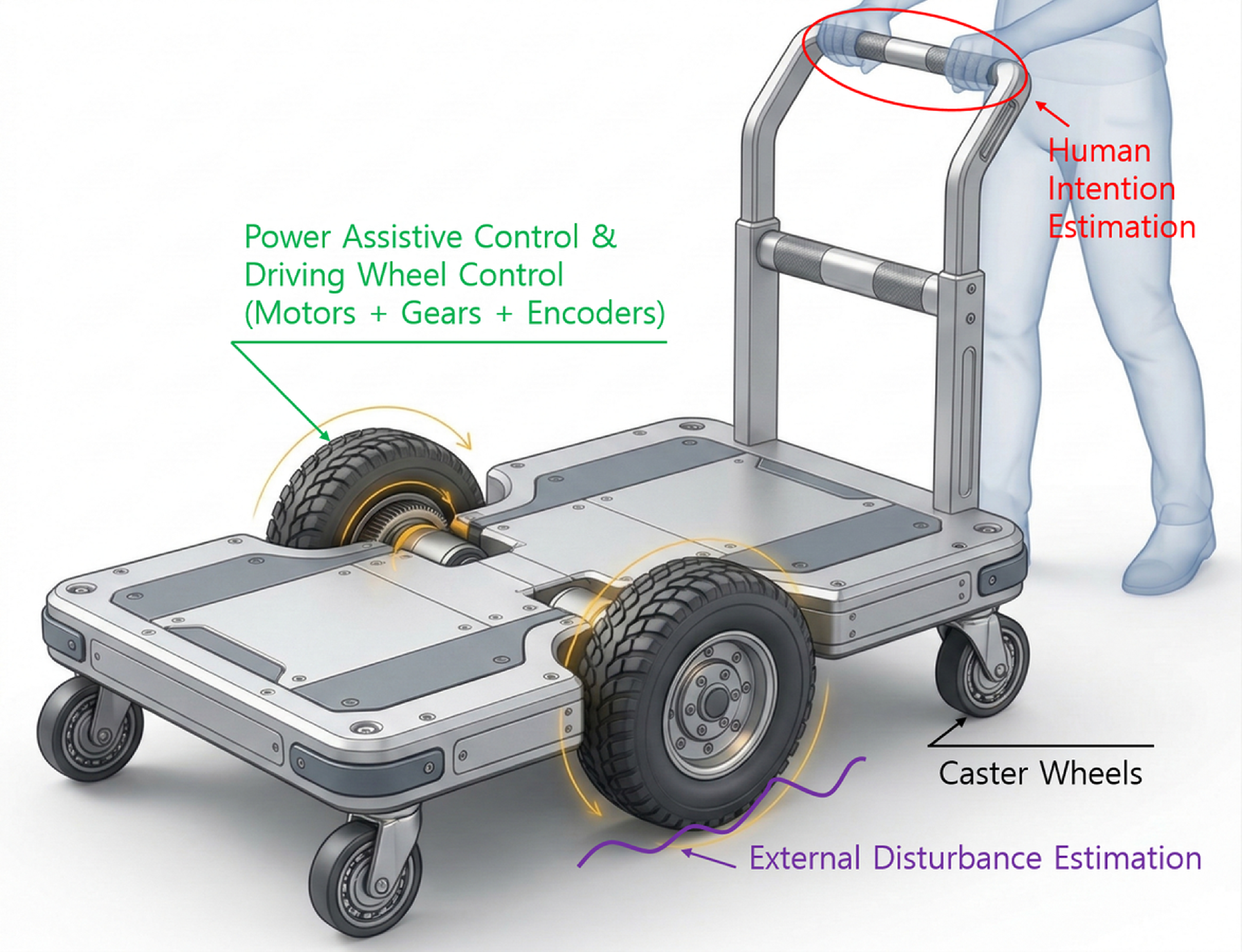
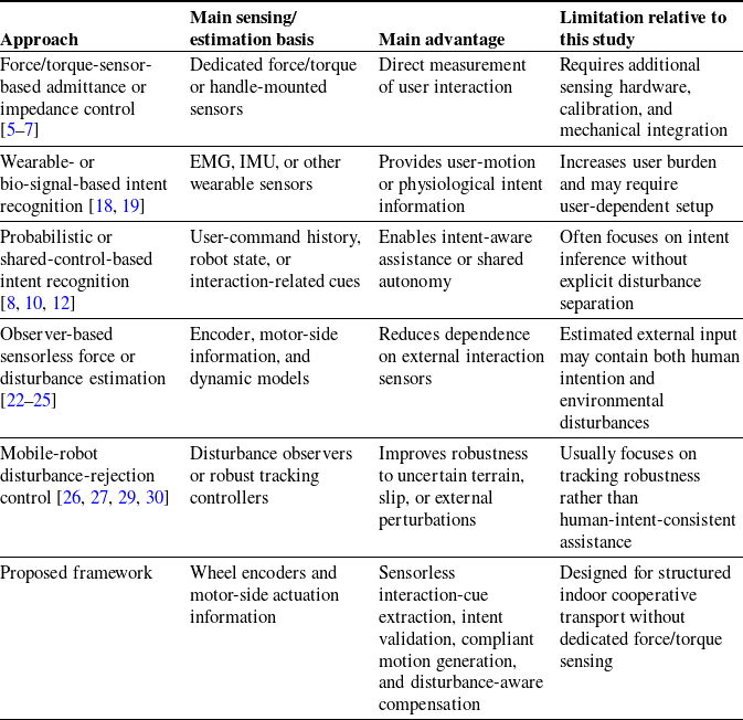
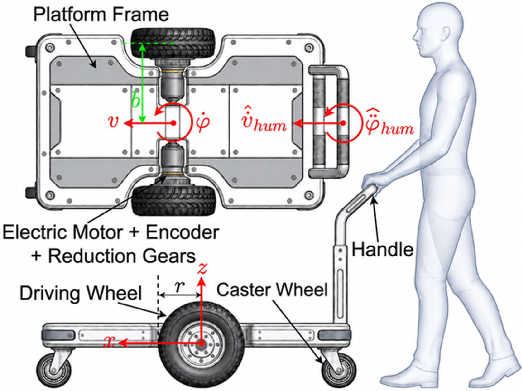
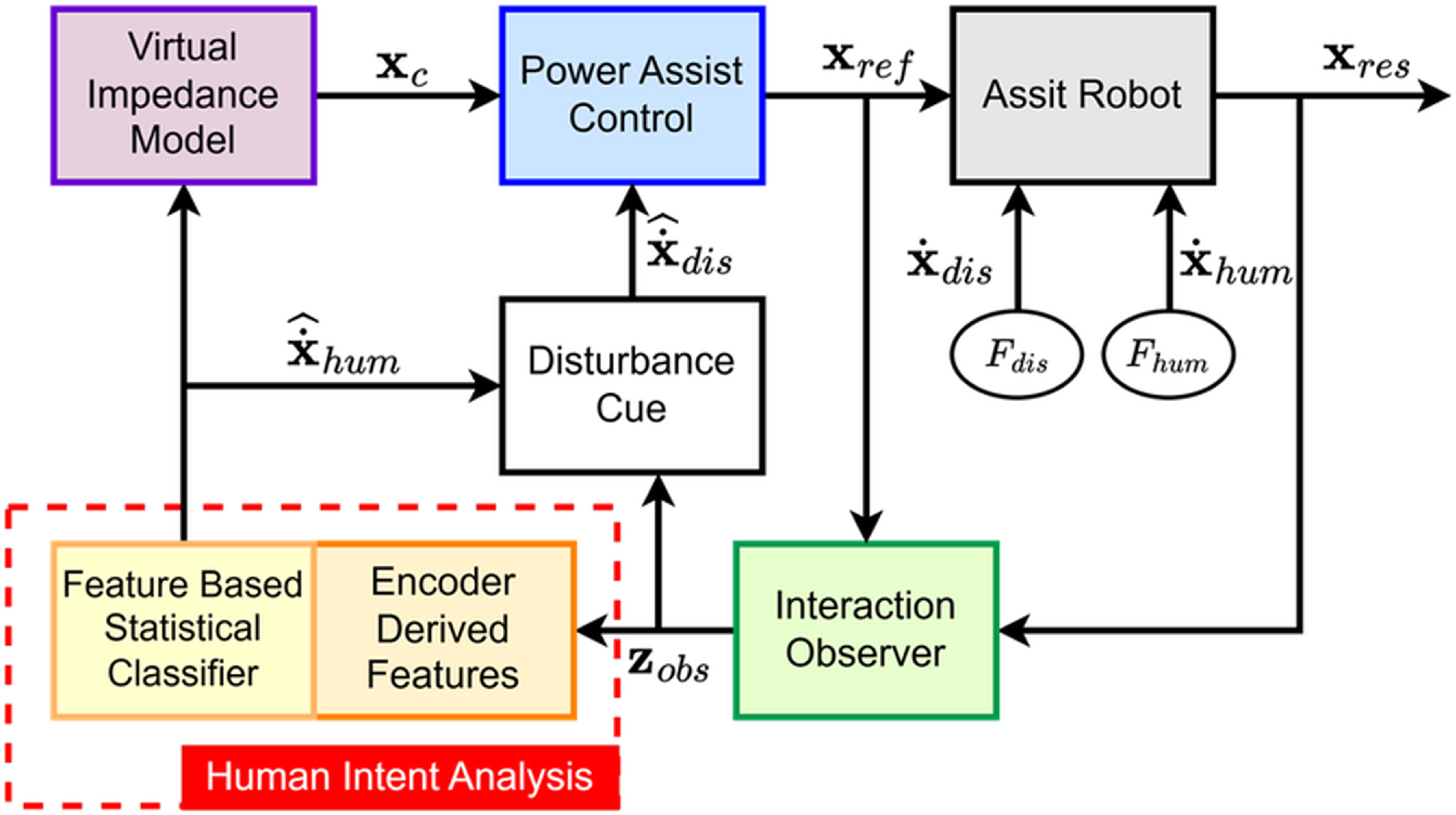
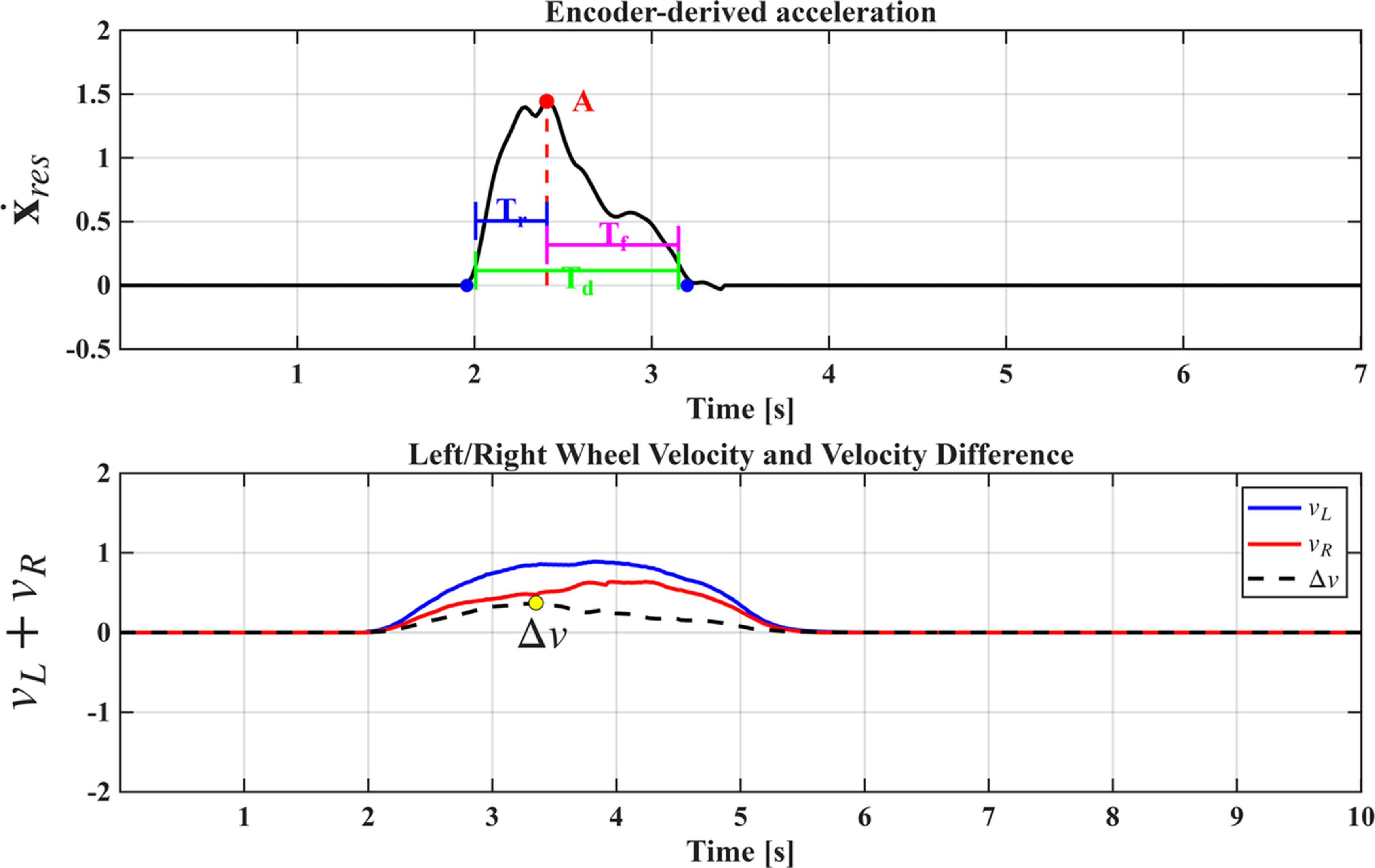
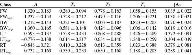
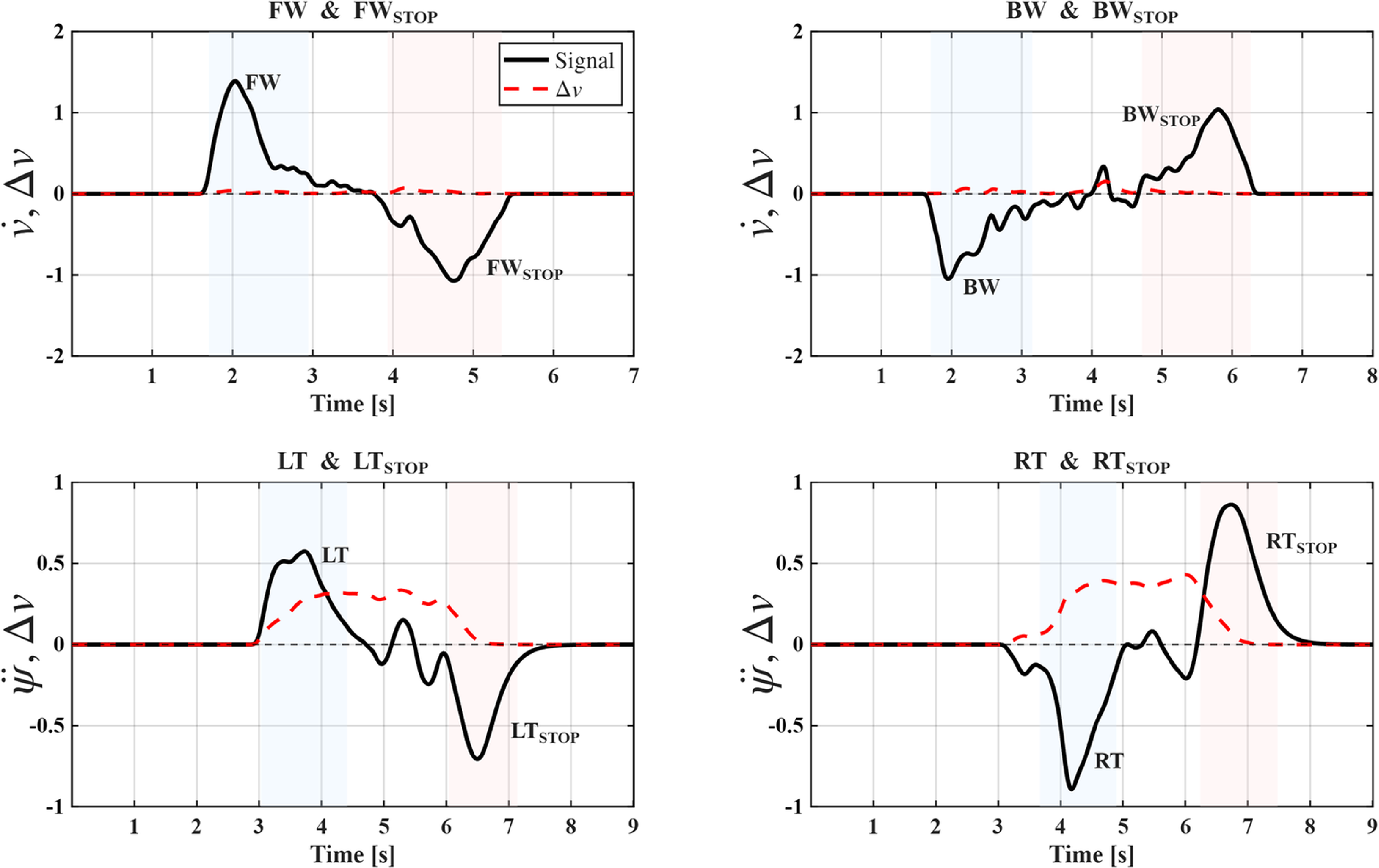
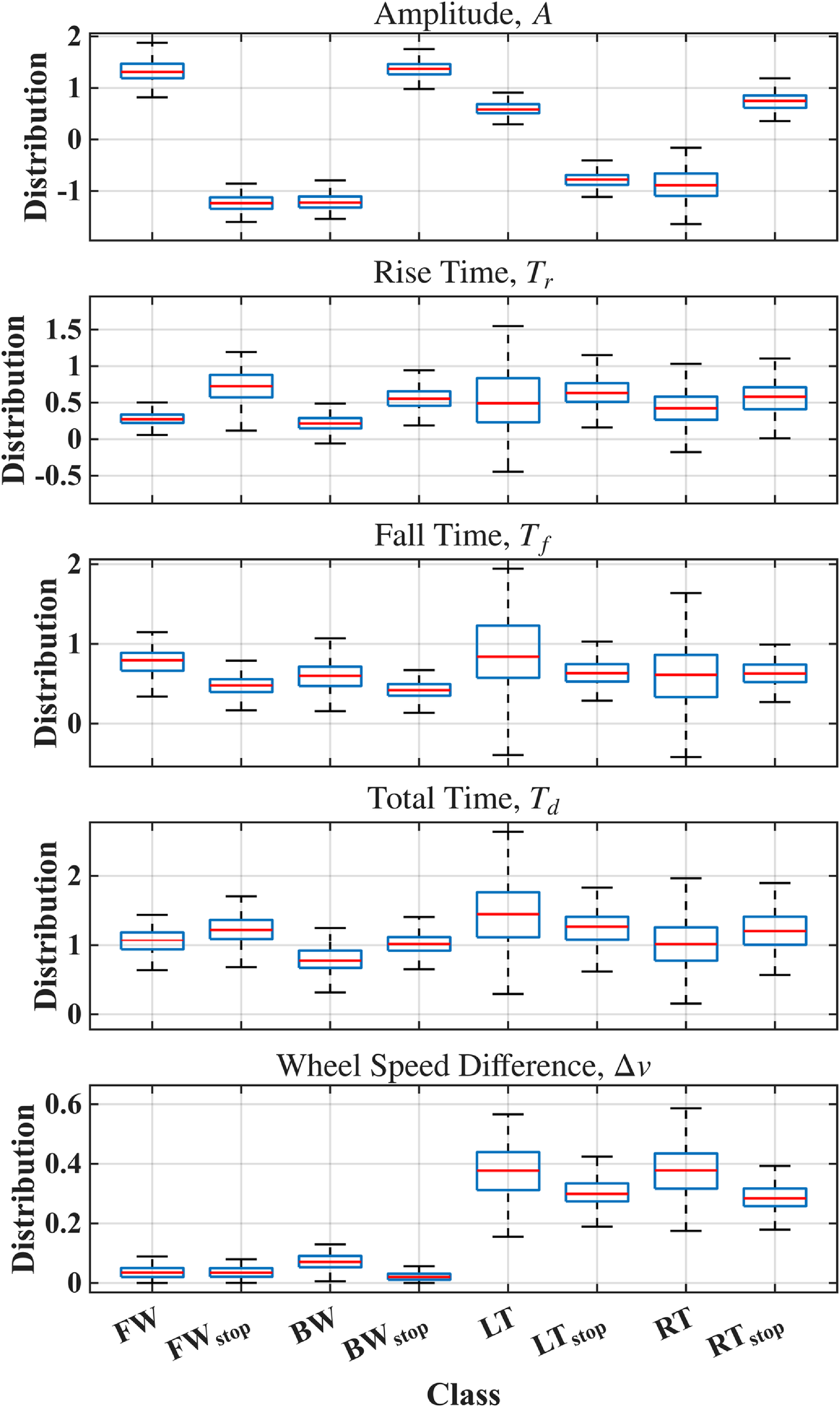
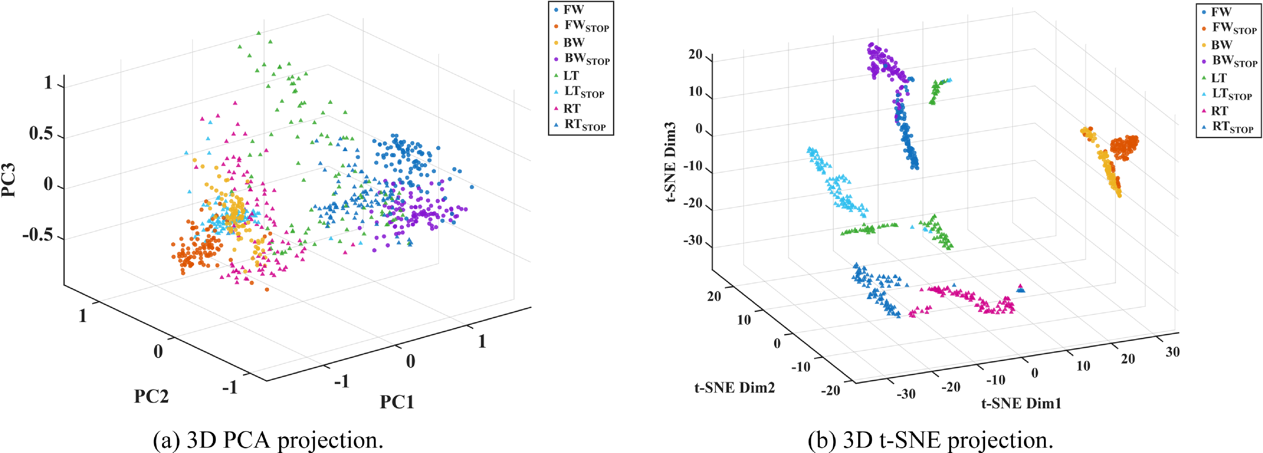
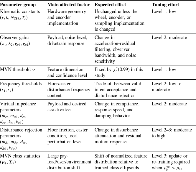
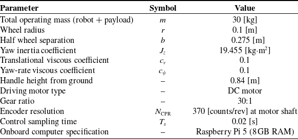
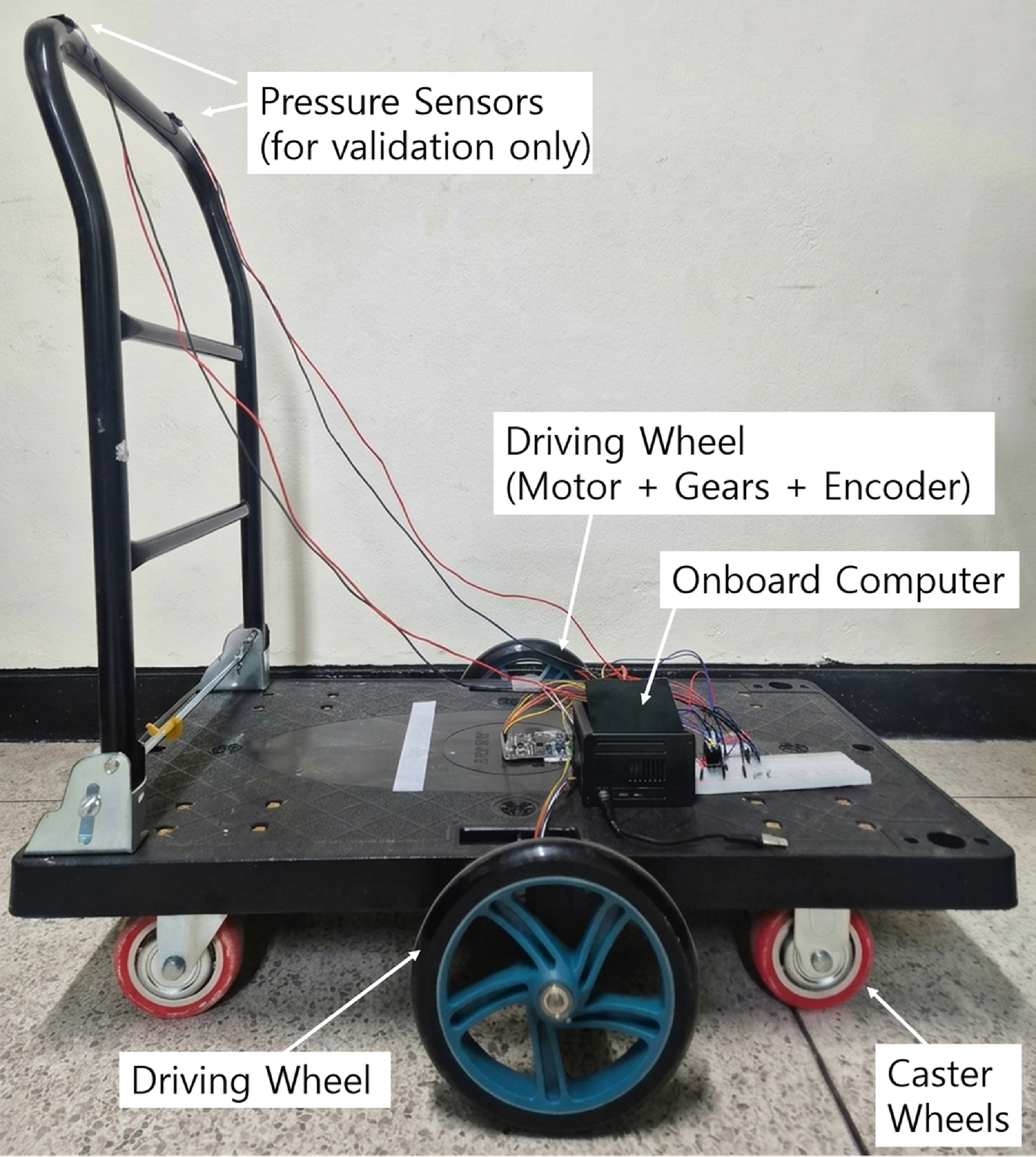
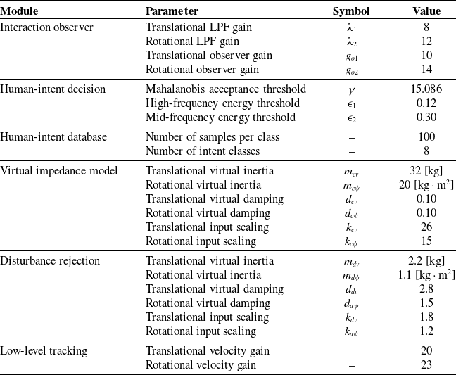

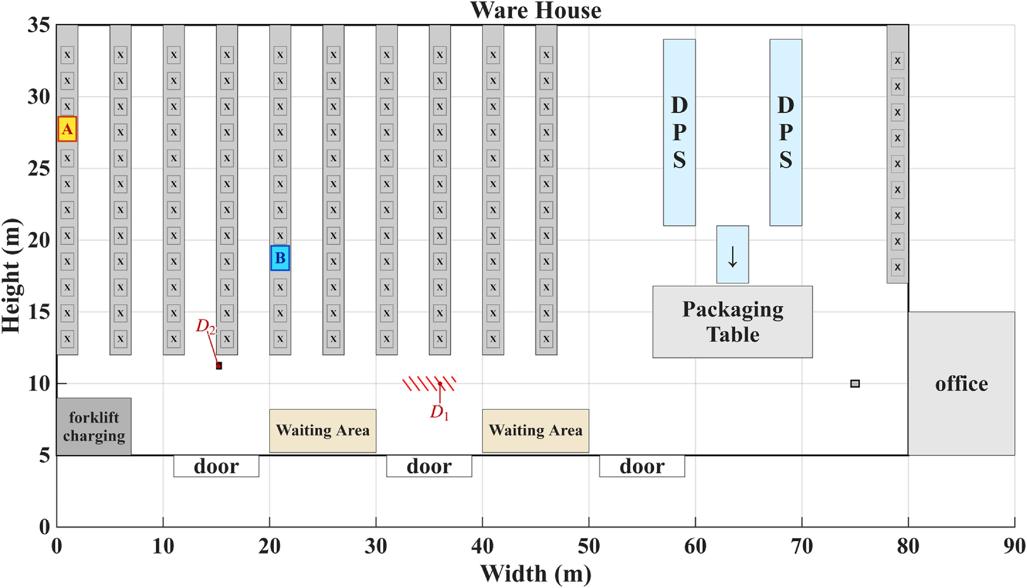
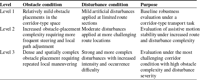
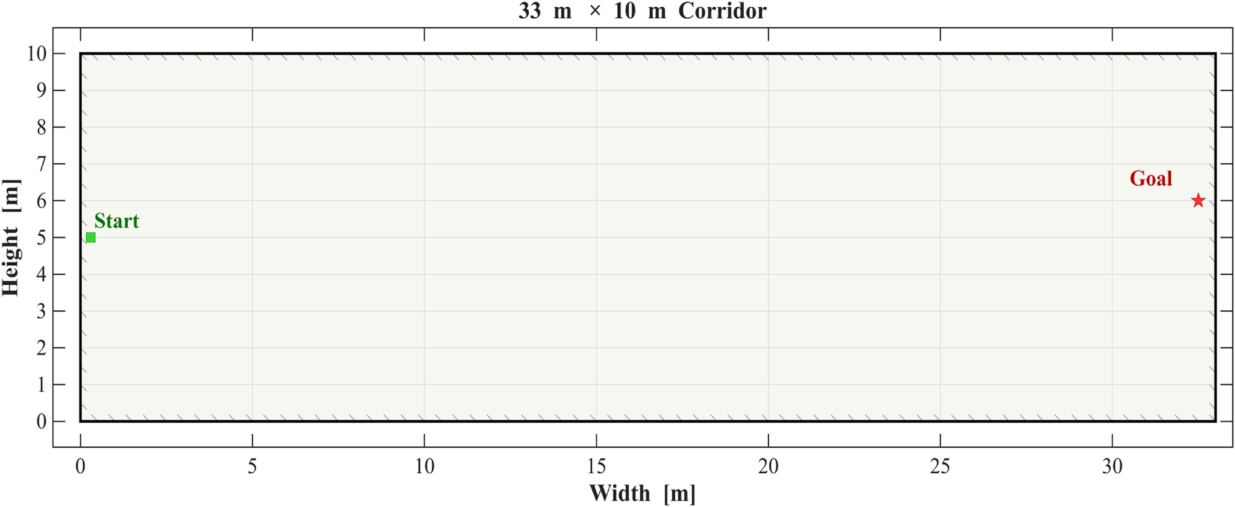
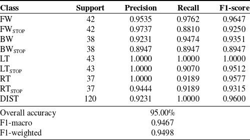
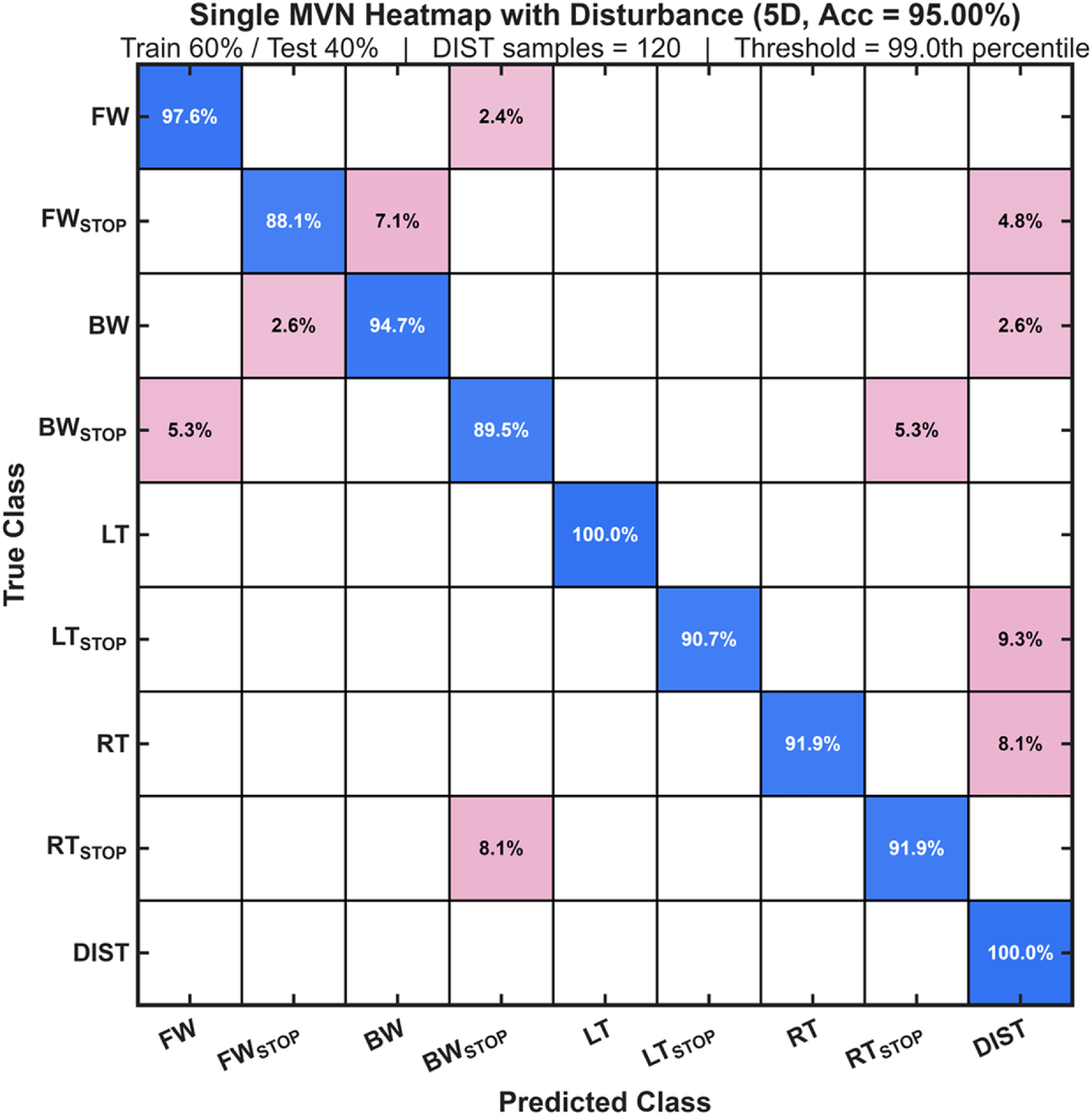

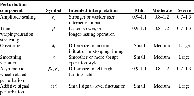
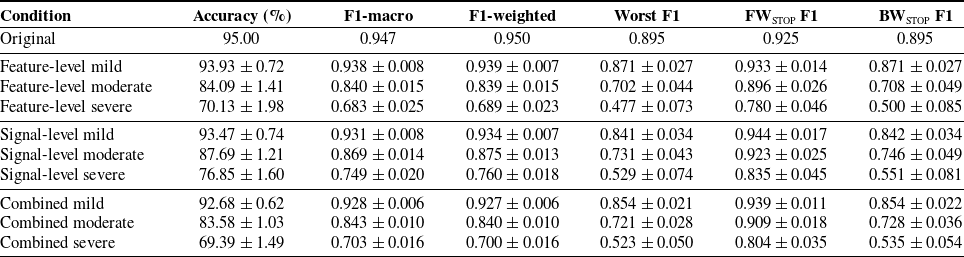
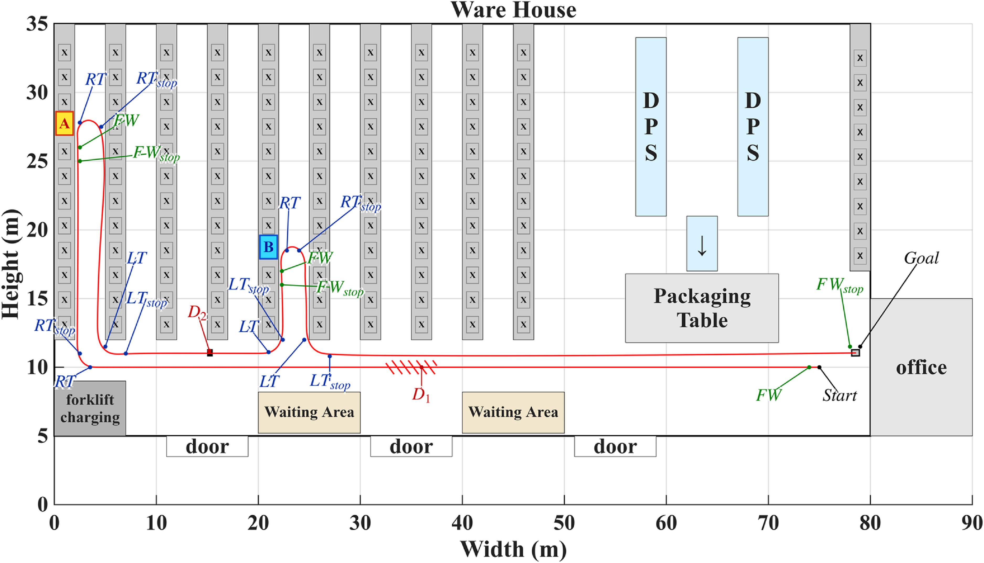
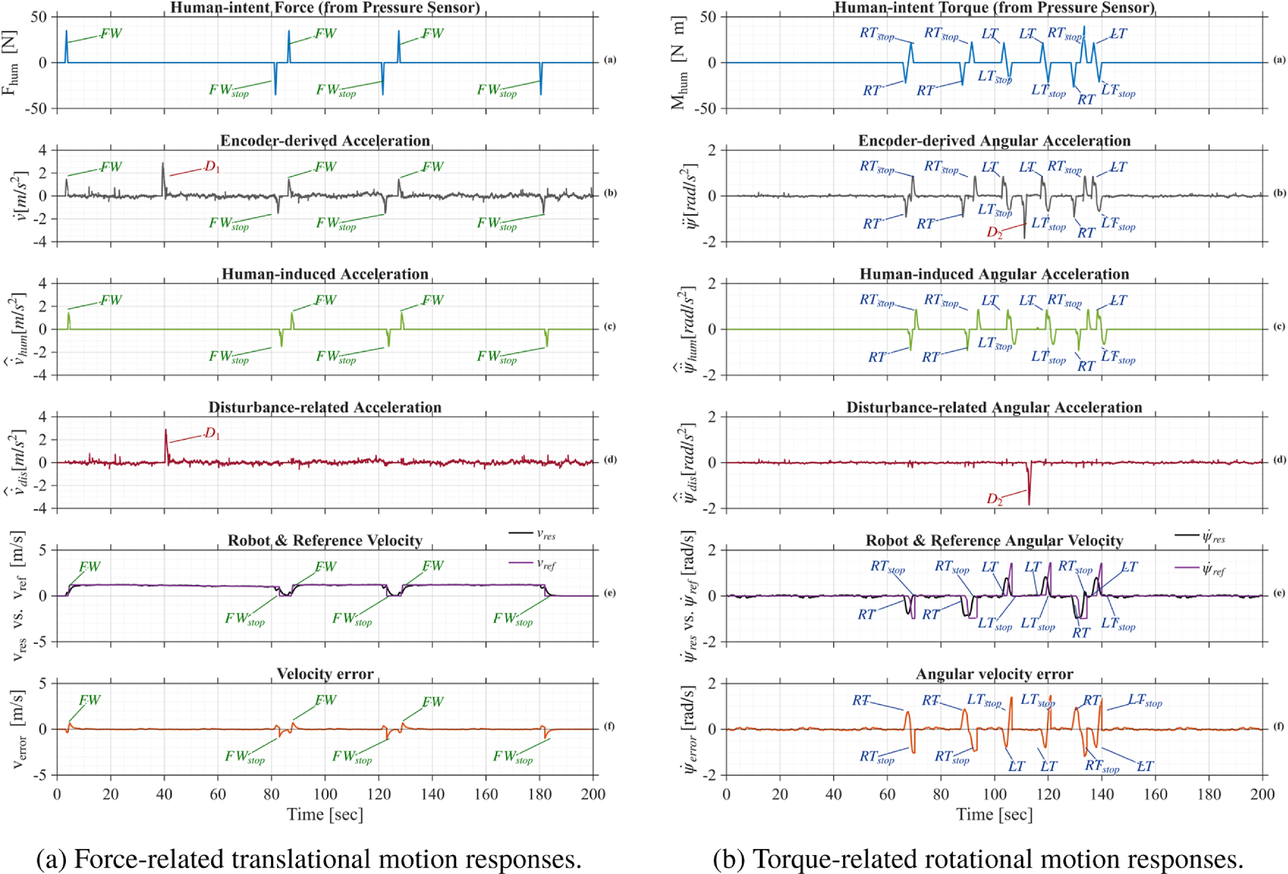
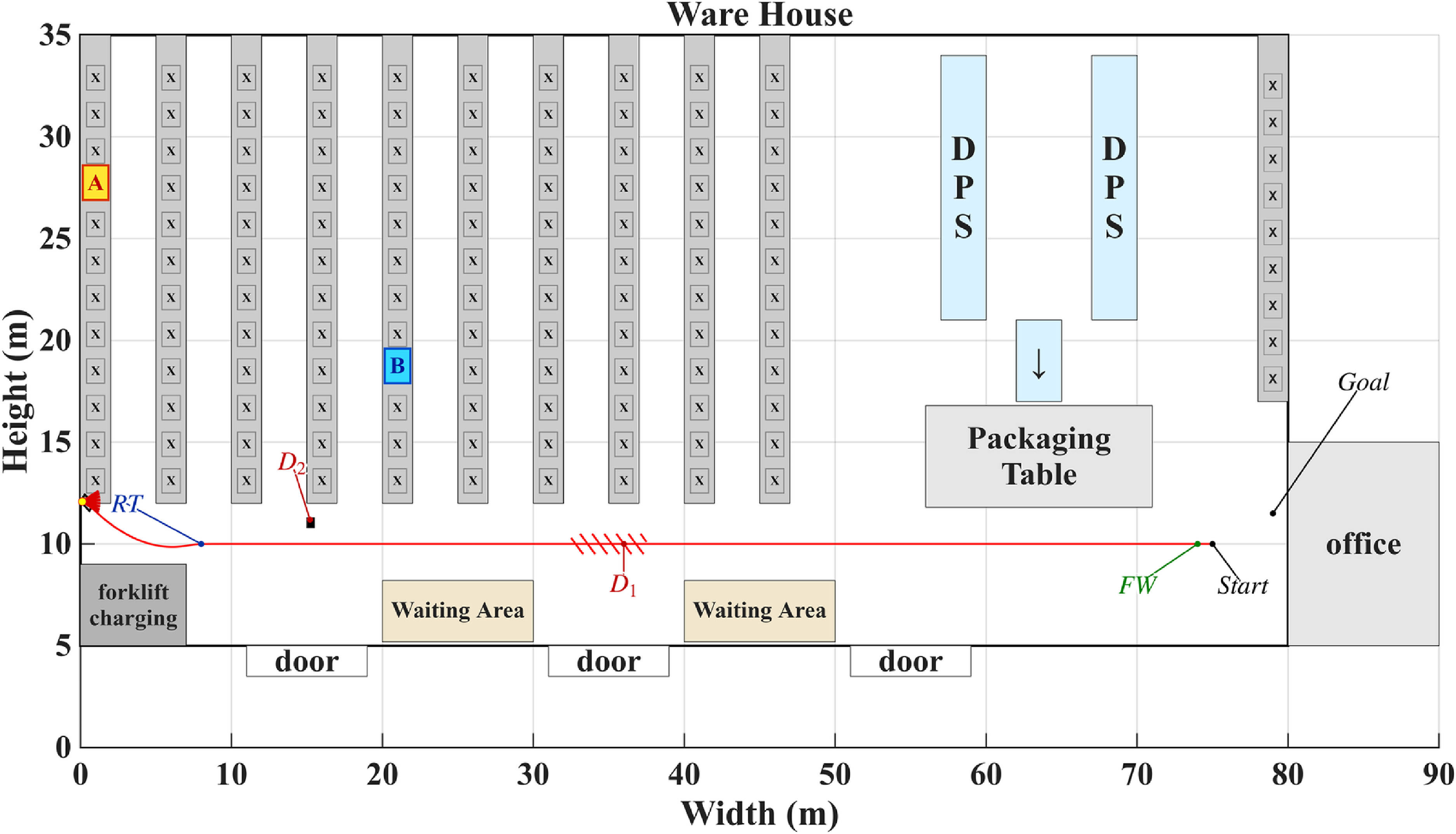
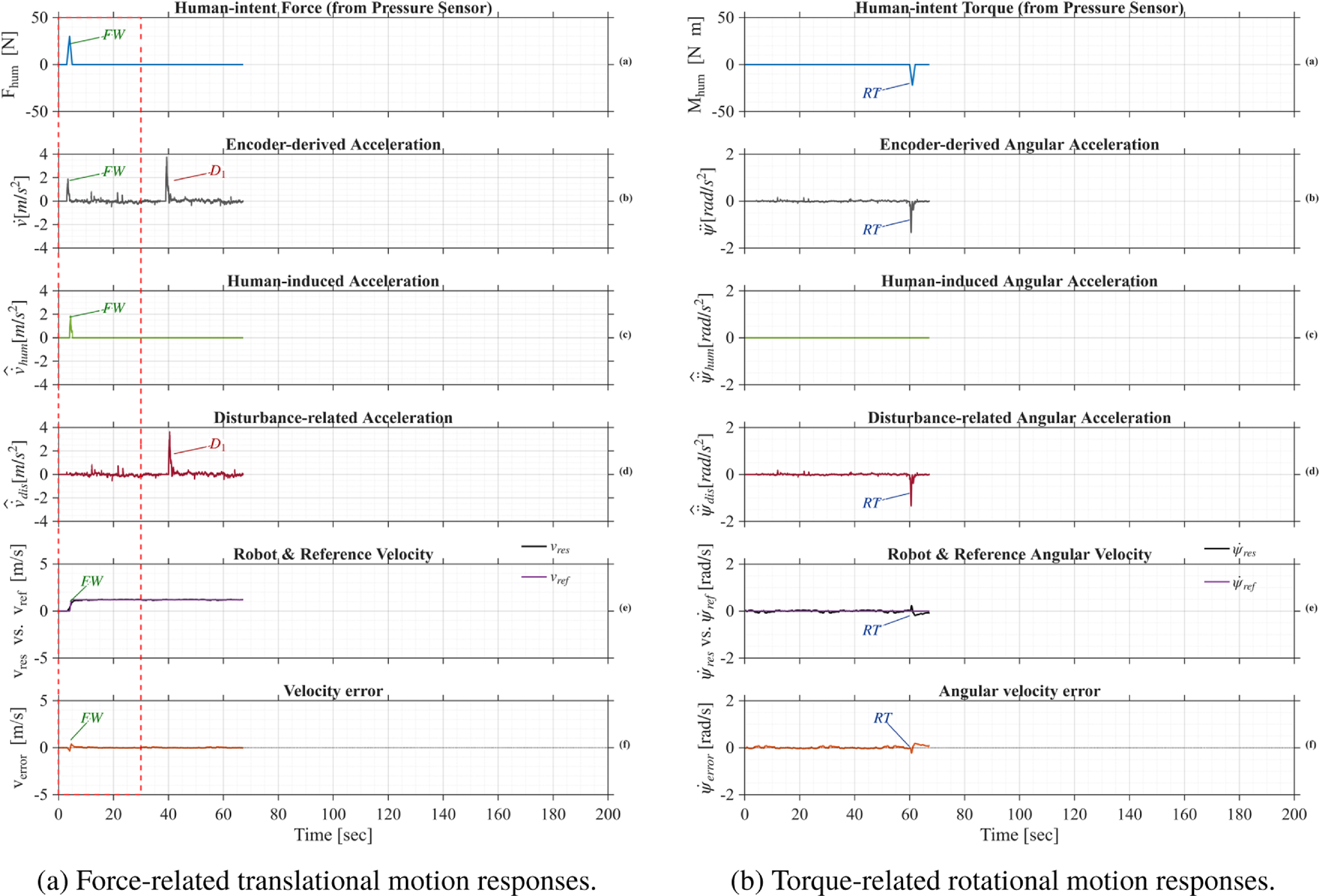
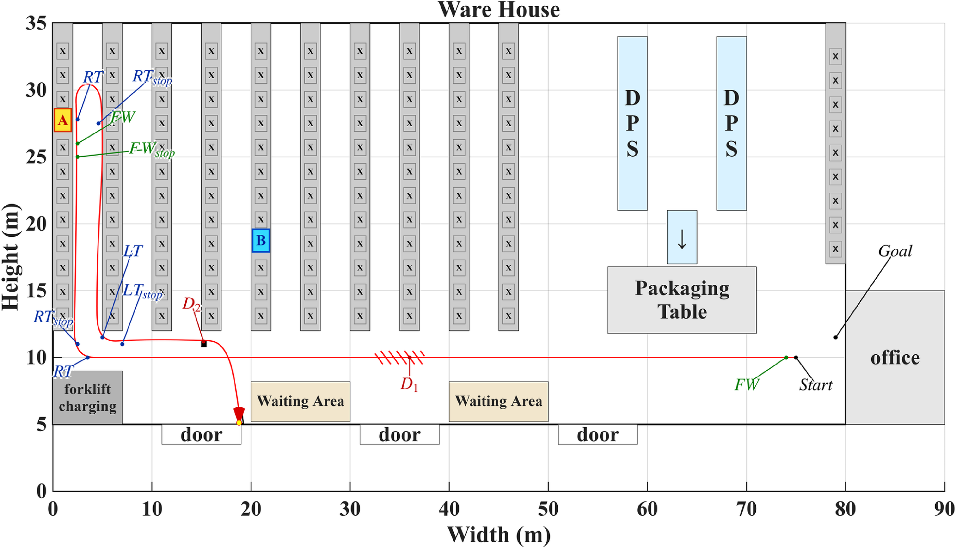
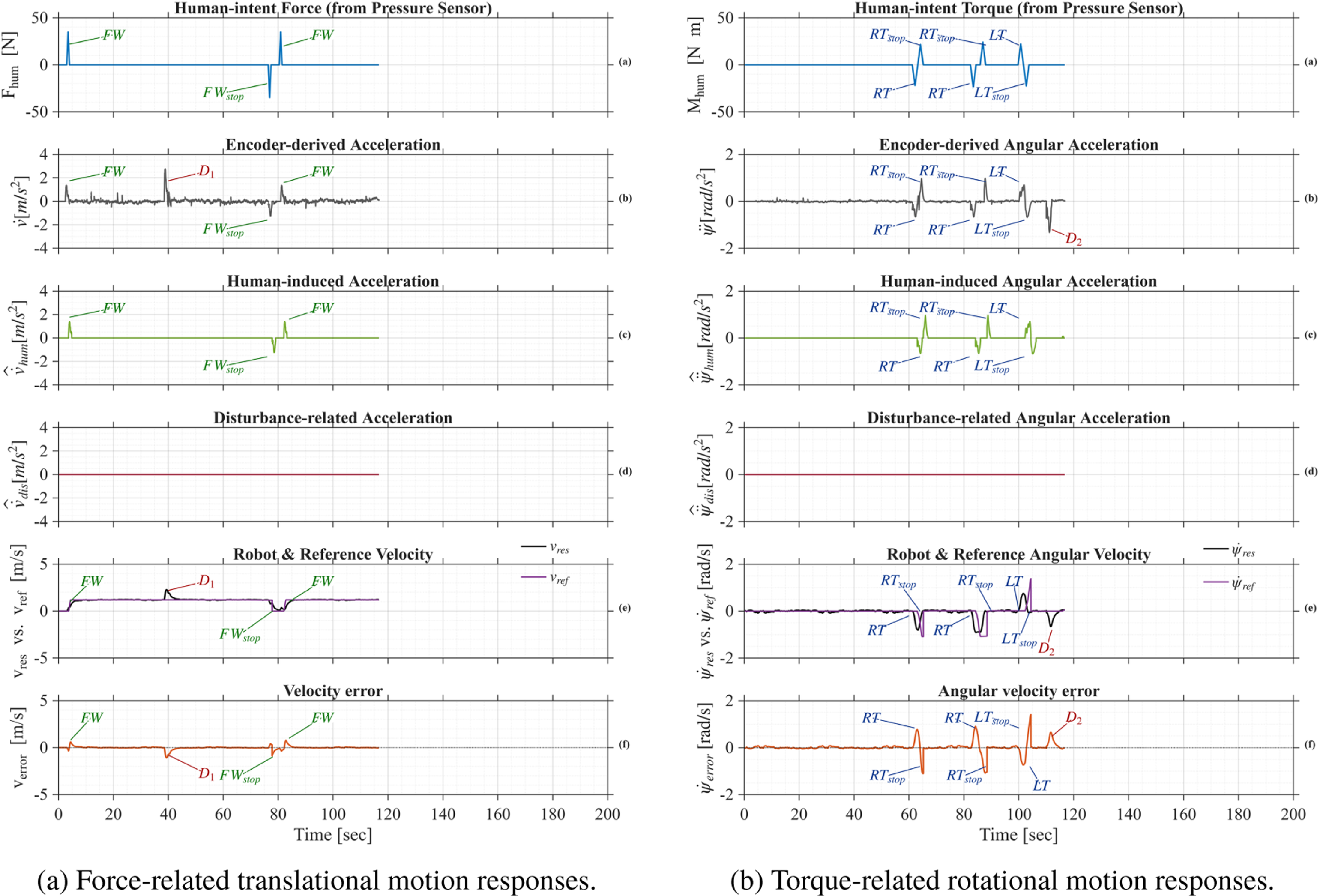
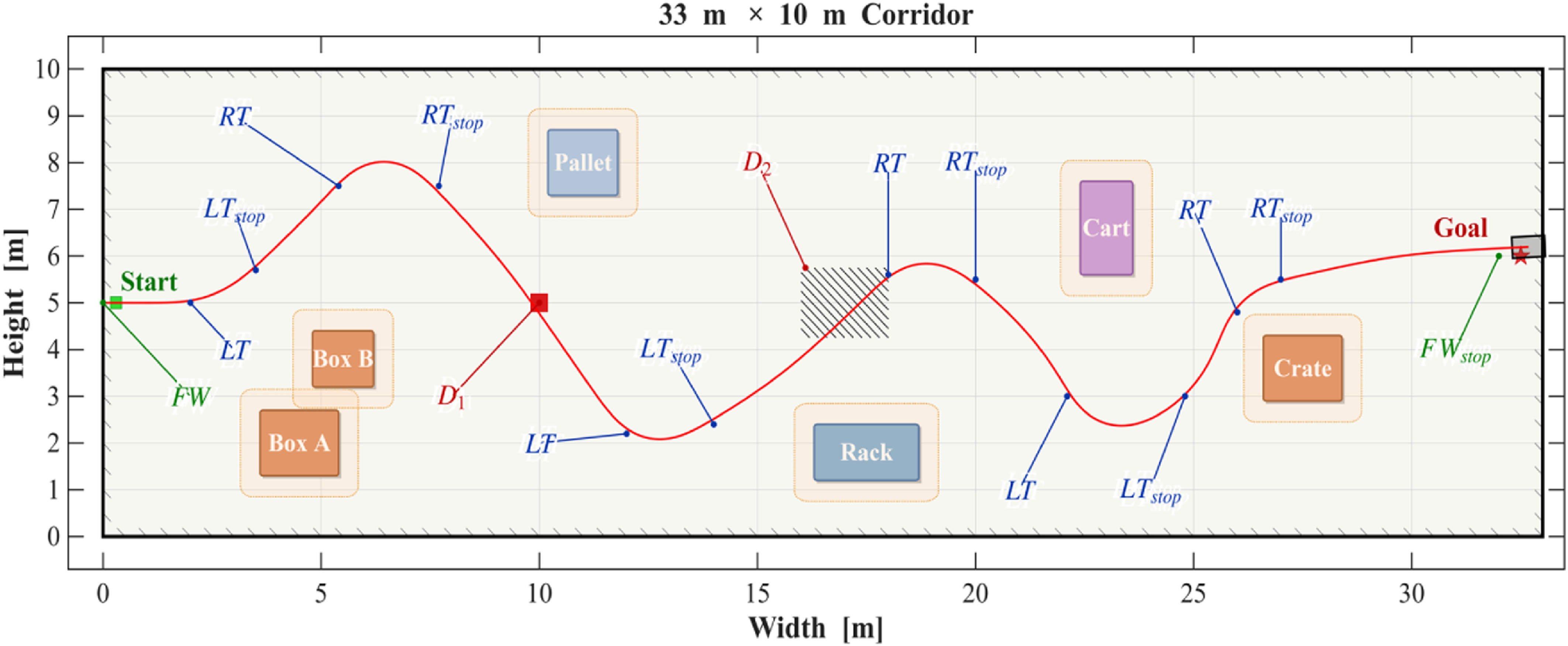
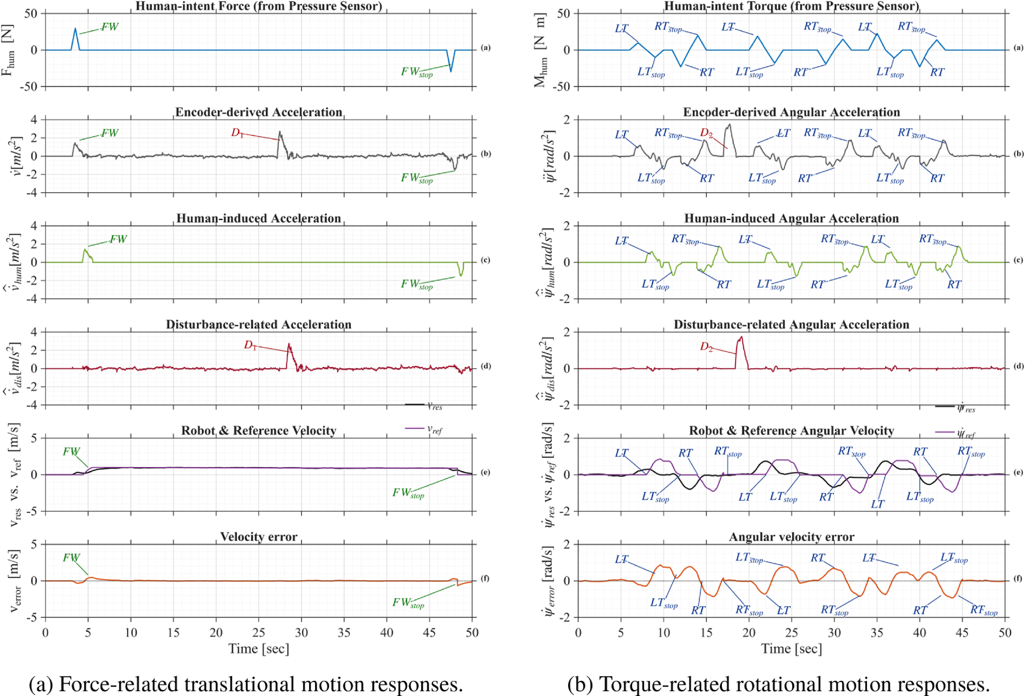
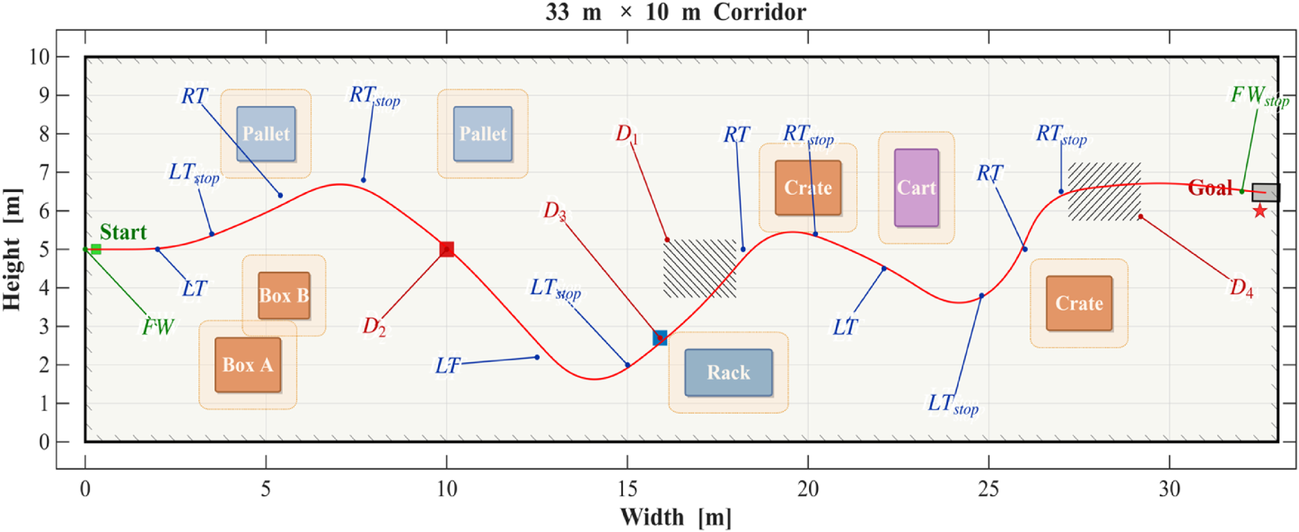
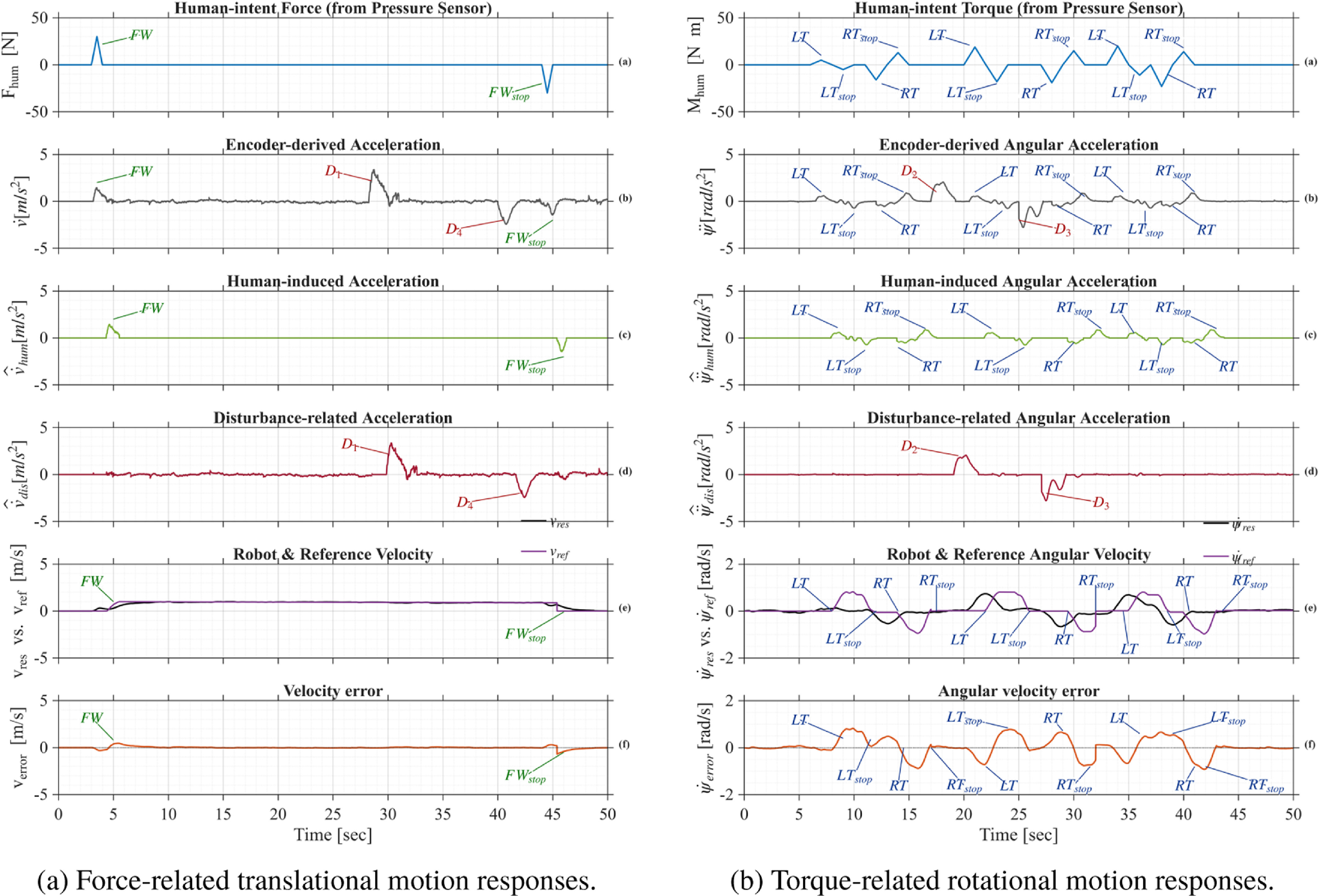
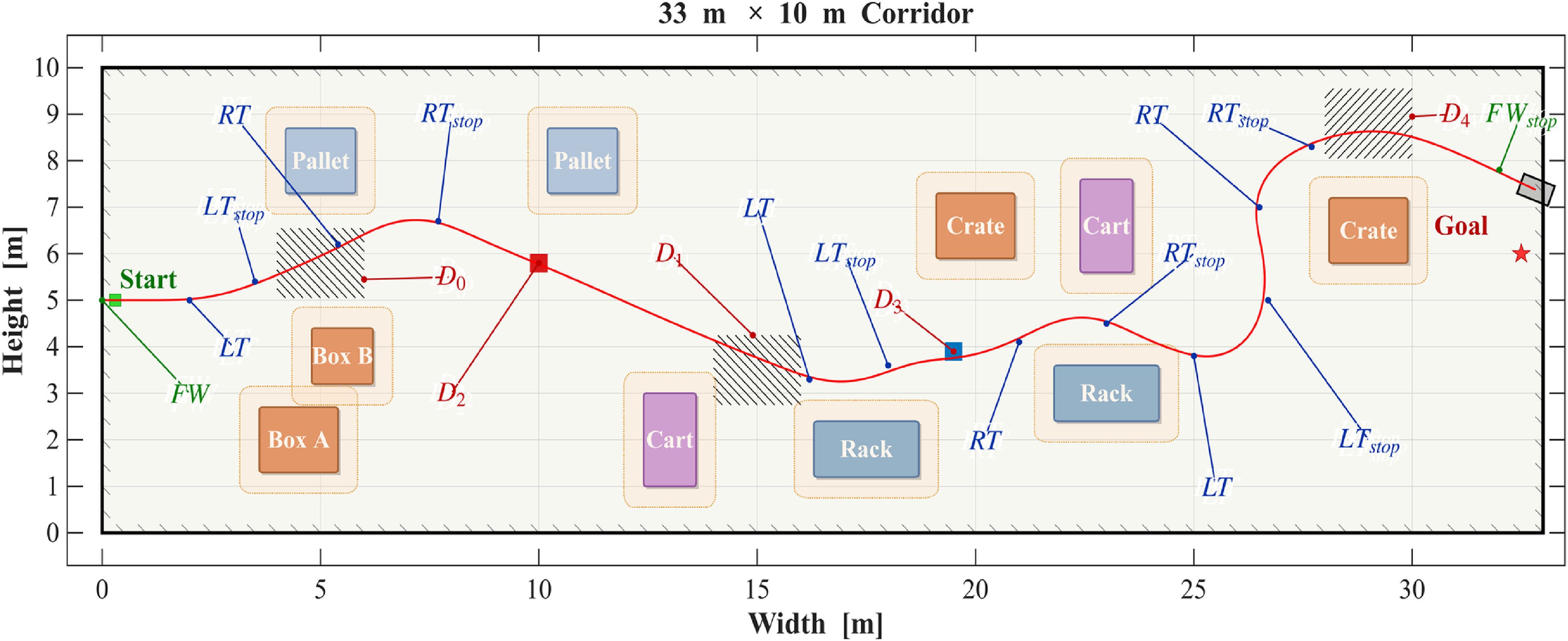
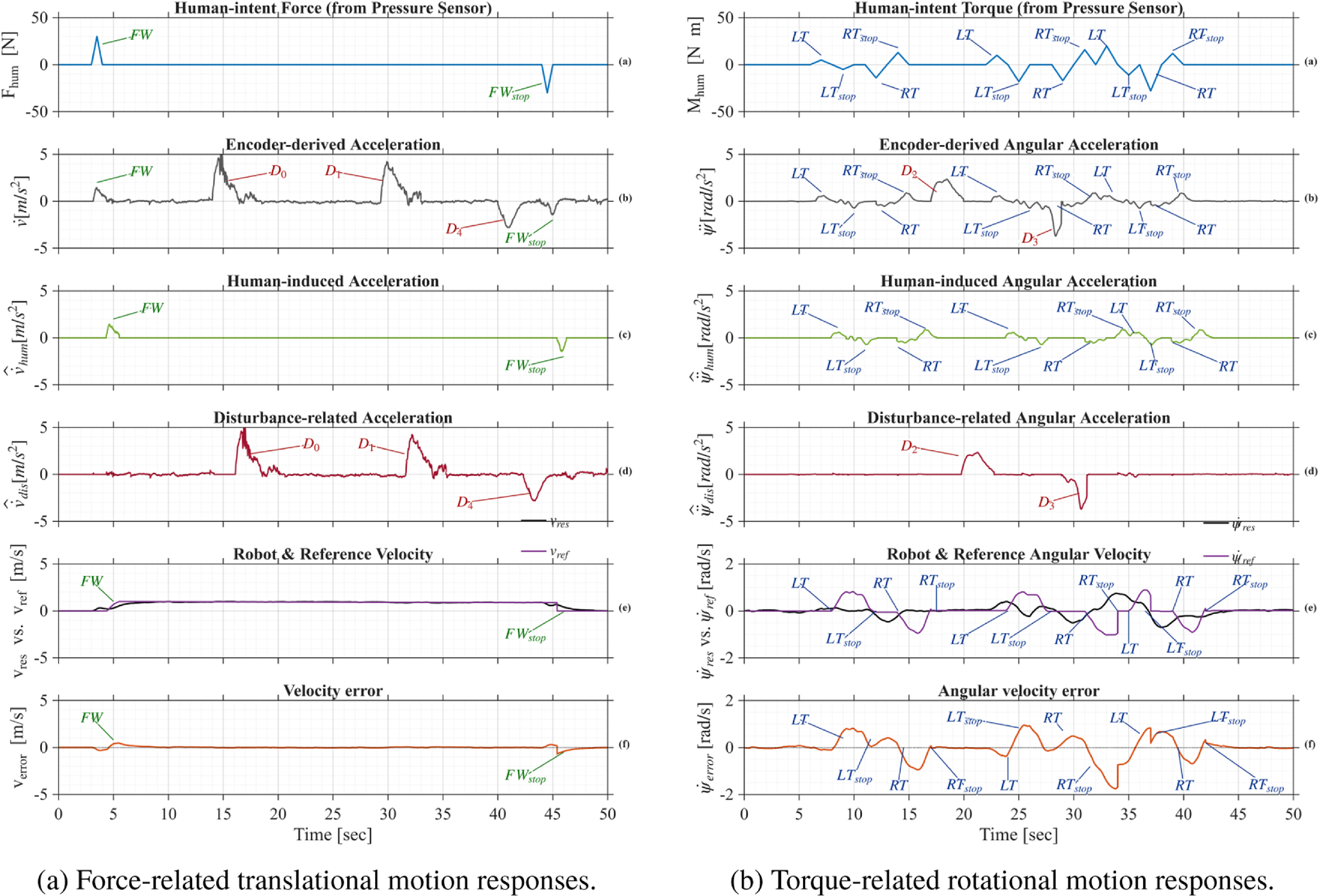

 Open access

