1 Introduction
Nowadays, microfluidic devices are increasingly used for fundamental and exploratory studies in chemistry and biology. Applications span from separation to dissolution processes including reactions, which are all strongly coupled to bubble dynamics (Mikaelian, Haut & Scheid Reference Mikaelian, Haut and Scheid2015a
,Reference Mikaelian, Haut and Scheid
b
). In addition, the mixing (Günther et al.
Reference Günther, Khan, Thalmann, Trachsel and Jensen2004) and mass transfer between the disperse and continuous phases (Mikaelian et al.
Reference Mikaelian, Haut and Scheid2015a
) enhanced by flow recirculation patterns provide a good ambient for microreactions. Recently, bubble dissolution in microchannels has become of great interest for its application in
 $\text{CO}_{2}$
sequestration or reactant dissolution (Shim et al.
Reference Shim, Wan, Hilgenfeldt, Panchal and Stone2014). In addition, micrometric solid particles, drops, bubbles and more intricate objects such as capsules and cells can be easily manipulated with the help of a continuous phase. Continuous flow separation devices rely on hydrodynamic forces, known as migration forces (Pamme Reference Pamme2007) and modulated either by the geometry, such as obstacles, patterns on the channel surface or varying channel section, or by body forces of gravitational, centrifugal, electrical, magnetic or acoustical origin.
Hydrodynamic forces have drawn the interest of the scientific community since the experiments of Segré & Silberberg (Reference Segré and Silberberg1962) on the migration of rigid spheres in Poiseuille flow of inertial origin. Subsequently, a series of experimental data (Tachibana Reference Tachibana1973) was obtained in parallel with a theoretical background (Ho & Leal Reference Ho and Leal1974; Schonberg & Hinch Reference Schonberg and Hinch1989) for rigid spheres. The effects of the particle rotation (Oliver Reference Oliver1962), the shear stress in linear profiles (Vasseur & Cox Reference Vasseur and Cox1976; McLaughlin Reference McLaughlin1991) and the presence of a wall (Vasseur & Cox Reference Vasseur and Cox1977) have also been addressed. Vasseur & Cox (Reference Vasseur and Cox1976) studied the dynamics of particles sedimenting in a stagnant fluid, shear flow and parabolic flow as well as the wall effect (Vasseur & Cox Reference Vasseur and Cox1977). Centrifugal forces such as Dean ones have also been used to enhance cell ordering, with applications to cell-in-droplet encapsulation (Kemna et al. Reference Kemna, Schoeman, Wolbers, Vermes, Weitz and Van Den Berg2012).
The effect of the particle size on its dynamics is a current field of research and, recently, the transition from small particle size to moderate size and the wall effect have been studied by Hood, Lee & Roper (Reference Hood, Lee and Roper2015), showing the asymptotic behaviour for small particles. Differential behaviour with respect to particle size has been successfully exploited for particle sorting (Di Carlo et al. Reference Di Carlo, Edd, Irimia, Tompkins and Toner2008). The influence of large-Reynolds-number flows on transverse equilibrium positions has also been explored experimentally by Matas, Morris & Guazzelli (Reference Matas, Morris and Guazzelli2004), showing different migration patterns depending on the Reynolds number.
One decade after inertial migration was discovered, the migration force induced by the deformability of drops was addressed by Chan & Leal (Reference Chan and Leal1979). The wall effect was shown by Kennedy, Pozrikidis & Skalak (Reference Kennedy, Pozrikidis and Skalak1994) to be always repulsive. Numerical simulations on the transient evolution of capillary migration of large drops have been carried out by Coulliette & Pozrikidis (Reference Coulliette and Pozrikidis1998) and Mortazavi & Tryggvason (Reference Mortazavi and Tryggvason2000), who revealed that the stability of the centred positions of drops strongly depends on the viscosity ratio in the limit of small Reynolds numbers. Recently, experiments and transient simulations of deformable bubbles have been carried out by Chen et al. (Reference Chen, Xue, Zhang, Hu, Jiang and Sun2014), who also considered the effect of inertia. In this case, they showed how equilibrium positions move to the centreline as the increasing Reynolds number causes larger deformations. They also compared with inertial migration of rigid particles, which is the limit of large inner to outer viscosity ratio.
In the other limit, sufficiently small viscosity ratio represents the case of clean bubbles. In this limit, Kennedy et al. (Reference Kennedy, Pozrikidis and Skalak1994) studied the wall effect, the repulsive character of which was confirmed by Takemura, Magnaudet & Dimitrakopoulos (Reference Takemura, Magnaudet and Dimitrakopoulos2009) in the case of bubbles rising close to the wall. Stan et al. (Reference Stan, Guglielmini, Ellerbee, Caviezel, Stone and Whitesides2011, Reference Stan, Ellerbee, Guglielmini, Stone and Whitesides2013) described several mechanisms of migration of drops and bubbles in microchannels and focused on inertial and capillary migrations. They carried out a comparison between numerical and experimental results, and they concluded that analytical theories of inertial (Ho & Leal Reference Ho and Leal1974) and capillary (Chan & Leal Reference Chan and Leal1979) migrations do not provide a satisfactory quantitative prediction of migration forces, and also that the migration forces are very difficult to measure experimentally. Despite these works, the dynamics of bubbles has attracted little attention in the literature, and a systematical study of the equilibrium state is still missing, especially in the presence of an external force.
Migration forces have also been studied with more complex surface/bulk rheologies such as thermocapillary stresses (Subramanian Reference Subramanian1983), Marangoni stresses with bulk-insoluble surfactant (Pak, Feng & Stone Reference Pak, Feng and Stone2014), for viscoelastic disperse media (Leshansky et al. Reference Leshansky, Bransky, Korin and Dinnar2007) and soft capsules (Singh, Li & Sarkar Reference Singh, Li and Sarkar2014).
The general problem of the transverse migration of particles, drops and bubbles has been addressed using several approaches such as experimental, analytical and numerical ones. As an analytical approach, regular asymptotic expansion for the Reynolds numbers has been used in the inertial migration problem (Cox & Brenner Reference Cox and Brenner1968), together with matched asymptotic expansion in the bubble size, then limiting the solution to small particle/bubble sizes as well as sufficiently large separation between the bubble and the wall (Schonberg & Hinch Reference Schonberg and Hinch1989). Further, the transient evolution has been numerically computed using the level set method (Yang et al. Reference Yang, Wang, Joseph, Hu, Pan and Glowinski2005; Stan et al. Reference Stan, Guglielmini, Ellerbee, Caviezel, Stone and Whitesides2011) or using surface tracking methods, such as the arbitrary Lagrangian–Eulerian method (Yang et al. Reference Yang, Wang, Joseph, Hu, Pan and Glowinski2005) or the boundary element method (Zhou & Pozrikidis Reference Zhou and Pozrikidis1993). If the transient behaviour is not relevant, the equilibrium solution can be obtained while skipping the transient evolution by solving the steady state, as performed by Mikaelian et al. (Reference Mikaelian, Haut and Scheid2015a ). The latter approach allows, in terms of computational cost, systematic parametrical analysis.
In the literature, several mechanisms of the dynamics of particles, drops and bubbles have been explored with different techniques, and in most of the cases, the dependence on the parameters governing the problem has been only qualitatively addressed, the main reasons being the computational cost of transient simulations, limitations of analytical techniques or experimental difficulties in the measurement of migration forces, besides the relatively large number of parameters describing the problem. Even though asymptotic expansion has been addressed for the case of migration, the validity of its limits has not been reported. Moreover, direct coupling between inertial and capillary effects has been relatively unexplored compared with their separate effects.
In this paper, we study inertial and capillary migrations in steady conditions in the presence of an external force in a circular microchannel, i.e. a microchannel with a circular cross-section. First, we write the governing equations, which consist of the Navier–Stokes equations at a domain containing one bubble and moving at the bubble velocity, together with no-slip boundary conditions at the walls of the channel and periodic boundary conditions between the inlet and outlet sections of a segment of the channel, i.e. the pressure gradient and velocity profile are periodic except for a pressure drop. We also consider both rigid and stress-free interfaces of the bubble, as well as deformable bubbles with surface tension. We systematically explore the transverse equilibrium position depending on the Reynolds and capillary numbers, as well as the bubble size and uniform body force. We derive regular asymptotic expansions for small Reynolds and/or capillary numbers. The latter expansion involves the linearisation of boundary conditions applied at a deformed boundary, and we propose a new approach for this task. We validate these expansions by comparison with the solution of the full system of equations and obtain the range of Reynolds and capillary numbers for which they are valid. We first focus on neutral bubbles, i.e. in the absence of body force, to obtain their stable and unstable positions, and then explore the effect of the body force. The stability character of centred positions is also discussed. We finally study the joint effect of inertia and capillary deformation on the equilibrium positions of neutral bubbles in the first-order expansion as well as the stability of centred bubbles in the full system of equations.
The structure of the paper is as follows. In § 2, we present the model we use to describe the dynamics of a train of bubbles of finite size and explain the underlying hypotheses. The boundary conditions at the bubble surface are given in § 2.1 for undeformable bubbles and in § 2.2 for deformable bubbles. Additional comments on the scaling and the numerics are given in § 2.3. In § 3, we present the results. In § 3.1, we study the effect of inertia, considering the limit of small Reynolds number, and explore its range of validity. Analogously, in § 3.2, we investigate the effect of bubble deformation in the small-capillary-number limit and investigate its range of validity. In both cases, we focus on the neutral bubbles as a reference and the stability of the centred position, as well as the effect of the body force. We complete our study, comparing inertial and capillary effects around the centred position, solving the full system of equations and recovering the small-Reynolds-number and small-capillary-number limits in § 3.3. Conclusions are presented in § 4.
Sketch of the modelled segment of a train of bubbles in a microchannel.

2 Modelling
We model the dynamics of a train of bubbles in a circular microchannel. Different equilibrium positions are possible depending on the bubble size and on the balance of several forces such as viscous, inertial, capillary and body forces. To model this situation, we consider a volume
 ${\mathcal{V}}$
containing one bubble of volume
 ${\mathcal{V}}_{B}$
, or equivalent diameter
 $d=\sqrt[3]{6{\mathcal{V}}_{B}/\unicode[STIX]{x03C0}}$
, attached to it and delimited by the walls of the channel,
 $\unicode[STIX]{x1D6F4}_{W}$
, two cross-sections of the channel,
 $\unicode[STIX]{x1D6F4}_{IN}$
and
 $\unicode[STIX]{x1D6F4}_{OUT}$
, and the bubble surface,
 $\unicode[STIX]{x1D6F4}_{B}$
, as schematised in figure 1. It is assumed that the characteristic time in which changes of volume of the bubble occur, either due to dissolution or due to the compressibility of the gas, is large compared with the time one bubble needs to cover its own size (Mikaelian et al.
Reference Mikaelian, Haut and Scheid2015a
,Reference Mikaelian, Haut and Scheid
b
) and, therefore, the evolution of the bubble can be considered as quasisteady in the absence of either vortex shedding or turbulence, as considered in this work. We include the influence of a uniform body force
 $\boldsymbol{f}$
exerted on the liquid (for gravity
 $\boldsymbol{f}=\unicode[STIX]{x1D70C}\boldsymbol{g}$
) in the transverse direction. A liquid of density
 $\unicode[STIX]{x1D70C}$
, viscosity
 $\unicode[STIX]{x1D707}$
and surface tension
 $\unicode[STIX]{x1D6FE}$
flows inside a channel of hydraulic diameter
 $d_{h}$
with a mean velocity
 $J$
, producing a pressure drop due to the Poiseuille flow modified by the presence of one bubble,
 $\unicode[STIX]{x0394}p$
, along a segment of length
 $L$
taken sufficiently large to avoid bubbles from interfering with one another. The bubble travels with a velocity
 $V$
and with a transverse equilibrium position
 $\unicode[STIX]{x1D73A}$
measured from the centre of the channel and determined by the balance of forces acting on the bubble surface in the transverse direction. The bubble might eventually rotate. Periodic boundary conditions are considered in the ‘IN’ and ‘OUT’ cross-sections; velocity
 $V$
is imposed at the wall of the channel such that the frame of reference is moving with the bubble. The bubble velocity is determined by the balance of forces acting on the bubble surface in the streamwise direction. Two different conditions are considered at the bubble surfaces, either rigid or stress-free. In the latter case, capillary deformation of the bubble will also be investigated.
According to the previous description, the liquid flow around the bubble in the modelled segment of the channel can be analysed by solving, in the reference frame attached to the bubble, the steady Navier–Stokes equations for incompressible fluids,
 $$\begin{eqnarray}\displaystyle \unicode[STIX]{x1D735}\boldsymbol{\cdot }\boldsymbol{v} & = & \displaystyle 0\quad \text{at }{\mathcal{V}},\end{eqnarray}$$
 $$\begin{eqnarray}\displaystyle \unicode[STIX]{x1D70C}\boldsymbol{v}\boldsymbol{\cdot }\unicode[STIX]{x1D735}\boldsymbol{v} & = & \displaystyle \unicode[STIX]{x1D735}\boldsymbol{\cdot }\hat{\unicode[STIX]{x1D749}}\quad \text{at }{\mathcal{V}},\end{eqnarray}$$
 $\boldsymbol{v}$
and
 $\hat{\unicode[STIX]{x1D749}}=-\hat{p}{\mathcal{I}}+\unicode[STIX]{x1D707}[\unicode[STIX]{x1D735}\boldsymbol{v}+(\unicode[STIX]{x1D735}\boldsymbol{v})^{\text{T}}]$
are respectively the velocity and the reduced stress tensor in which
 $\hat{p}$
is the reduced pressure and
 ${\mathcal{I}}$
is the identity tensor. The pressure is then written as
 $p=\hat{p}+\boldsymbol{f}\boldsymbol{\cdot }(\boldsymbol{x}-\unicode[STIX]{x1D73A})$
with the reference hydrostatic pressure chosen at the centre of the bubble without loss of generality. In this work, we consider that the uniform body force is transverse to the streamwise direction, i.e.
 $$\begin{eqnarray}\boldsymbol{f}\boldsymbol{\cdot }\boldsymbol{e}_{x}=0.\end{eqnarray}$$
In the reference frame attached to the bubble moving at the equilibrium velocity
 $V$
, the velocity of the liquid at the wall is written as
 $$\begin{eqnarray}\boldsymbol{v}(\boldsymbol{x})=-V\boldsymbol{e}_{x}\quad \text{at }\unicode[STIX]{x1D6F4}_{W},\end{eqnarray}$$
whereas the equilibrium condition for the bubble, using the generalised Stokes theorem (A 1), is
 $$\begin{eqnarray}\boldsymbol{{\mathcal{L}}}\equiv \int _{\unicode[STIX]{x1D6F4}_{B}}\boldsymbol{n}\boldsymbol{\cdot }\hat{\unicode[STIX]{x1D749}}\,\text{d}\unicode[STIX]{x1D6F4}={\mathcal{V}}_{B}\hspace{1.0pt}\boldsymbol{f},\end{eqnarray}$$
where
 $\boldsymbol{{\mathcal{L}}}$
,
 $\boldsymbol{n}$
and
 $\text{d}\unicode[STIX]{x1D6F4}$
are the migration force, the outer normal vector and the differential surface element respectively. Thus, we equivalently refer hereafter to the balanced body force,
 $\boldsymbol{f}$
, instead of the migration force,
 $\boldsymbol{{\mathcal{L}}}$
, it is in equilibrium with.
The velocity profile and pressure gradient in Poiseuille flows are uniform, i.e. periodic with any period, in the streamwise direction. Thus, the pressure field between two different cross-sections differs by a constant pressure difference. The presence of bubbles sets the period to the distance between consecutive bubbles,
 $L$
,
 $$\begin{eqnarray}\displaystyle \hat{p}(\boldsymbol{x}+L\boldsymbol{e}_{x}) & = & \displaystyle \hat{p}(\boldsymbol{x})-\unicode[STIX]{x0394}p+L\unicode[STIX]{x2202}_{x}p_{P}\quad \text{at }\unicode[STIX]{x1D6F4}_{cross},\end{eqnarray}$$
 $$\begin{eqnarray}\displaystyle \boldsymbol{v}(\boldsymbol{x}+L\boldsymbol{e}_{x}) & = & \displaystyle \boldsymbol{v}(\boldsymbol{x})\quad \text{at }\unicode[STIX]{x1D6F4}_{cross},\end{eqnarray}$$
 $$\begin{eqnarray}\displaystyle \unicode[STIX]{x2202}_{x}\boldsymbol{v}(\boldsymbol{x}+L\boldsymbol{e}_{x}) & = & \displaystyle \unicode[STIX]{x2202}_{x}\boldsymbol{v}(\boldsymbol{x})\quad \text{at }\unicode[STIX]{x1D6F4}_{cross},\end{eqnarray}$$
 $\unicode[STIX]{x1D6F4}_{cross}$
is any cross-section and the pressure drop is the Poiseuille one,
 $\unicode[STIX]{x2202}_{x}p_{P}$
, modified by the presence of the bubble,
 $\unicode[STIX]{x0394}p$
, along the period
 $L$
. The periodic velocity profile has a mean velocity
 $J$
defined by
 $$\begin{eqnarray}\int _{\unicode[STIX]{x1D6F4}_{cross}}(\boldsymbol{v}\boldsymbol{\cdot }\boldsymbol{e}_{x}+V-J)\,\text{d}\unicode[STIX]{x1D6F4}=0.\end{eqnarray}$$
It can be observed that in the absence of bubbles,
 $\unicode[STIX]{x0394}p=0$
, and the limit of (2.5) divided by
 $L$
for
 $L\rightarrow 0$
leads to
 $\unicode[STIX]{x2202}_{x}\hat{p}=\unicode[STIX]{x2202}_{x}p_{P}$
,
 $\unicode[STIX]{x2202}_{x}\boldsymbol{v}=\mathbf{0}$
and
 $\unicode[STIX]{x2202}_{xx}\boldsymbol{v}=\mathbf{0}$
, which substituted into (2.1) and using (2.6) yield the Poiseuille pressure drop,
 $\unicode[STIX]{x2202}_{x}p_{P}=-32\unicode[STIX]{x1D707}J/d_{h}^{2}$
, in circular microchannels. Equations (2.5)–(2.6) must be imposed only at a single cross-section because of the periodicity, and we choose
 $\unicode[STIX]{x1D6F4}_{cross}\equiv \unicode[STIX]{x1D6F4}_{OUT}$
for convenience.
The injected energy is dissipated by the viscous forces which are modified by the presence of the bubble. This leads to an effective viscosity which can be measured as the ratio of the averaged pressure drop per unit length to the one induced by the Poiseuille flow. The averaged pressure drop per unit length,
 $\unicode[STIX]{x1D6E5}_{x}p_{T}$
, produced in a microchannel fulfils
 $\unicode[STIX]{x1D6E5}_{x}p_{T}=\unicode[STIX]{x2202}_{x}p_{P}-\unicode[STIX]{x0394}p/L$
. If one defines the bubble volumetric fraction
 $\unicode[STIX]{x1D6FC}_{G}={\mathcal{V}}_{B}/L\unicode[STIX]{x1D6F4}_{cross}$
, where the microchannel cross-section is
 $\unicode[STIX]{x1D6F4}_{cross}=(\unicode[STIX]{x03C0}/4)d_{h}^{2}$
, the normalised averaged pressure drop is written as
 $$\begin{eqnarray}\frac{\unicode[STIX]{x1D6E5}_{x}p_{T}}{\unicode[STIX]{x2202}_{x}p_{P}}=1+\unicode[STIX]{x1D6FD}\unicode[STIX]{x1D6FC}_{G},\end{eqnarray}$$
where
 $\unicode[STIX]{x1D6FD}$
is the pressure correction factor
 $\unicode[STIX]{x1D6FD}=-\unicode[STIX]{x1D712}\unicode[STIX]{x0394}p/\unicode[STIX]{x2202}_{x}p_{P}$
and the geometrical factor
 $\unicode[STIX]{x1D712}$
is
 $\unicode[STIX]{x1D712}=\unicode[STIX]{x1D6F4}_{cross}/{\mathcal{V}}_{B}=3d_{h}^{2}/2d^{3}$
in circular microchannels. Equation (2.7) has been experimentally investigated by Cubaud & Ho (Reference Cubaud and Ho2004) in the limit of small
 $\unicode[STIX]{x1D6FC}_{G}$
in square microchannels, with a wide dispersion around the value
 $\unicode[STIX]{x1D6FD}=1$
, which may be due to the actual dependence of the bubble size and transverse position. In fact,
 $\unicode[STIX]{x1D6FD}$
spans from negative to positive values, depending on
 $\unicode[STIX]{x0394}p$
, as will be shown later.
We consider different boundary conditions at the bubble surface depending on whether the capillary deformation of the bubble is taken into account.
2.1 Undeformable bubbles
First, we consider rigid and stress-free boundary conditions on the surfaces of undeformed bubbles. These are relevant for the study of inertial migration in the cases of infinite Marangoni effect and clean surface respectively.
On the one hand, in the limit of infinite Marangoni effect, the flow at the bubble surface corresponds to that of a rigid solid that rotates with rotational velocity
 $\unicode[STIX]{x1D734}$
and is determined by the no-slip condition and the equilibrium of moments respectively,
 $$\begin{eqnarray}\displaystyle \boldsymbol{v}(\boldsymbol{x}) & = & \displaystyle \unicode[STIX]{x1D734}\times (\boldsymbol{x}-\unicode[STIX]{x1D73A})\quad \text{at }\unicode[STIX]{x1D6F4}_{B},\end{eqnarray}$$
 $$\begin{eqnarray}\displaystyle \mathbf{0} & = & \displaystyle \int _{\unicode[STIX]{x1D6F4}_{B}}\boldsymbol{n}\boldsymbol{\cdot }\hat{\unicode[STIX]{x1D749}}\times (\boldsymbol{x}-\unicode[STIX]{x1D73A})\,\text{d}\unicode[STIX]{x1D6F4}.\end{eqnarray}$$
On the other hand, in the case of clean bubbles, the stress-free boundary condition, which consists of vanishing tangential stresses and the impermeability condition, is applied for the case of clean bubbles, i.e.
 $$\begin{eqnarray}\displaystyle \boldsymbol{n}\boldsymbol{\cdot }\hat{\unicode[STIX]{x1D749}} & = & \displaystyle -\hat{p}_{s}\boldsymbol{n}\quad \text{at }\unicode[STIX]{x1D6F4}_{B},\end{eqnarray}$$
 $$\begin{eqnarray}\displaystyle \boldsymbol{n}\boldsymbol{\cdot }\boldsymbol{v} & = & \displaystyle 0\quad \text{at }\unicode[STIX]{x1D6F4}_{B},\end{eqnarray}$$
 $\hat{p}_{s}$
is the reduced counterpart of the impermeable surface pressure
 $p_{s}=\hat{p}_{s}+\boldsymbol{f}\boldsymbol{\cdot }(\boldsymbol{x}-\unicode[STIX]{x1D73A})$
that the liquid exerts on the bubble surface. These conditions are the same as those governing the case of inviscid drops. Thus, their interactions with the liquid are identical.
2.2 Deformable bubbles
Second, we consider the case of deformable bubbles, which is relevant for the study of capillary migration. In this case, the surface position is governed by the following equilibrium of stresses and the impermeability condition:
 $$\begin{eqnarray}\displaystyle \boldsymbol{n}\boldsymbol{\cdot }\unicode[STIX]{x27E6}\unicode[STIX]{x1D749}\unicode[STIX]{x27E7} & = & \displaystyle \boldsymbol{D}_{S}\unicode[STIX]{x1D6FE}\quad \text{at }\unicode[STIX]{x1D6F4}_{B},\end{eqnarray}$$
 $$\begin{eqnarray}\displaystyle \boldsymbol{n}\boldsymbol{\cdot }\boldsymbol{v} & = & \displaystyle 0\quad \text{at }\unicode[STIX]{x1D6F4}_{B},\end{eqnarray}$$
 $\unicode[STIX]{x27E6}\unicode[STIX]{x1D749}\unicode[STIX]{x27E7}=[p_{G}-\boldsymbol{f}\boldsymbol{\cdot }(\boldsymbol{x}-\unicode[STIX]{x1D73A})]{\mathcal{I}}+\hat{\unicode[STIX]{x1D749}}$
is the jump of the stress tensor and the global variable
 $p_{G}$
, i.e. neither domain nor surface, is the gas pressure governed by the Young–Laplace law, which depends on the volume of the bubble,
 ${\mathcal{V}}_{B}$
. The exterior surface differential operator
 $\boldsymbol{D}_{S}$
is defined by its application to a quantity
 $\unicode[STIX]{x1D711}$
, either scalar, vector or tensor, as
 $$\begin{eqnarray}\int _{\unicode[STIX]{x1D6F4}}\boldsymbol{D}_{S}\unicode[STIX]{x1D711}\,\text{d}\unicode[STIX]{x1D6F4}=\int _{\unicode[STIX]{x1D6E4}}\boldsymbol{n}_{S}\unicode[STIX]{x1D711}\,\text{d}\unicode[STIX]{x1D6E4},\end{eqnarray}$$
where
 $\unicode[STIX]{x1D6F4}$
is a surface bounded by a contour
 $\unicode[STIX]{x1D6E4}$
, the outer normal of which is denoted by
 $\boldsymbol{n}_{S}$
. The vector
 $\boldsymbol{n}_{S}$
is perpendicular to the contour
 $\unicode[STIX]{x1D6E4}$
and to the outer normal vector of the surface
 $\unicode[STIX]{x1D6F4}$
,
 $\boldsymbol{n}$
, as schematised in figure 2. It should be noted that
 $\boldsymbol{D}_{S}\unicode[STIX]{x1D6FE}$
includes the normal pressure proportional to the curvature and the Marangoni effect (not considered in this work),
 $\boldsymbol{D}_{S}\unicode[STIX]{x1D6FE}=-\unicode[STIX]{x1D6FE}\boldsymbol{n}\unicode[STIX]{x1D735}_{\!S}\boldsymbol{\cdot }\boldsymbol{n}+\unicode[STIX]{x1D735}_{\!S}\unicode[STIX]{x1D6FE}$
, with
 $\unicode[STIX]{x1D735}_{\!S}=({\mathcal{I}}-\boldsymbol{n}\boldsymbol{n})\boldsymbol{\cdot }\unicode[STIX]{x1D735}$
the surface gradient operator.
Sketch of the contour
 $\unicode[STIX]{x1D6E4}$
limiting the fluid surface
 $\unicode[STIX]{x1D6F4}$
;
 $\boldsymbol{n}$
is the outer normal to the surface and
 $\boldsymbol{n}_{S}$
is the outer normal to the contour contained in
 $\unicode[STIX]{x1D6F4}$
such that
 $\boldsymbol{n}\boldsymbol{\cdot }\boldsymbol{n}_{S}=0$
.

Since
 $\unicode[STIX]{x1D6F4}_{B}$
for a bubble is a closed surface and has no contour, it can be inferred from (2.11) that the surface tension exerts no force on the bubble as a whole. Thus, the integral of (2.10a
) over
 $\unicode[STIX]{x1D6F4}_{B}$
leads to (2.4), and therefore (2.4) is redundant in the case of deformable bubbles.
Finally, since the domain is deformable, the volume and transverse position of the deformed bubble need to be defined,
 $$\begin{eqnarray}\displaystyle {\mathcal{V}}_{B} & = & \displaystyle \int _{{\mathcal{V}}_{B}}\text{d}{\mathcal{V}},\end{eqnarray}$$
 $$\begin{eqnarray}\displaystyle \mathbf{0} & = & \displaystyle \int _{{\mathcal{V}}_{B}}(\boldsymbol{x}-\unicode[STIX]{x1D73A})\,\text{d}{\mathcal{V}},\end{eqnarray}$$
 ${\mathcal{V}}_{B}$
is the domain occupied by the bubble.
2.3 Scaling and numerics
Equations (2.1)–(2.12) can be made dimensionless with the hydraulic diameter of the channel
 $d_{h}$
, the mean velocity of the flow
 $J$
and the viscous stress
 $\unicode[STIX]{x1D707}J/d_{h}$
as characteristic length, velocity and pressure respectively. Equations (2.1)–(2.12) are referred to hereafter as their dimensionless counterparts obtained by the substitution in these equations of
 $$\begin{eqnarray}d_{h}\rightarrow 1,\quad J\rightarrow 1,\quad \unicode[STIX]{x1D707}\rightarrow 1,\quad \unicode[STIX]{x1D70C}\rightarrow Re,\quad \unicode[STIX]{x1D6FE}\rightarrow Ca^{-1},\quad\end{eqnarray}$$
where the dimensionless numbers are
 $$\begin{eqnarray}Re=\frac{\unicode[STIX]{x1D70C}Jd_{h}}{\unicode[STIX]{x1D707}},\quad Ca=\frac{\unicode[STIX]{x1D707}J}{\unicode[STIX]{x1D6FE}}.\end{eqnarray}$$
Typical values for water in a microchannel of diameter
 $d_{h}=500~\unicode[STIX]{x03BC}\text{m}$
and a flow rate of
 $J=0.1~\text{m}~\text{s}^{-1}$
correspond to dimensionless numbers of
 $Re=50$
and
 $Ca=1.4\times 10^{-3}$
. The dimensional domain variables can be recovered by
 $$\begin{eqnarray}\boldsymbol{v}\leftarrow J\boldsymbol{v},\quad \hat{p}\leftarrow \frac{\unicode[STIX]{x1D707}J}{d_{h}}\hat{p}\end{eqnarray}$$
and the dimensional global variables by
 $$\begin{eqnarray}\displaystyle & \displaystyle \unicode[STIX]{x1D73A}\leftarrow d_{h}\unicode[STIX]{x1D73A},\quad d\leftarrow d_{h}d,\quad \boldsymbol{f}\leftarrow \frac{\unicode[STIX]{x1D707}J}{d_{h}^{2}}\boldsymbol{f},\quad V\leftarrow JV,\quad \unicode[STIX]{x0394}p\leftarrow \frac{\unicode[STIX]{x1D707}J}{d_{h}}\unicode[STIX]{x0394}p,\quad \unicode[STIX]{x1D734}\leftarrow \frac{J}{d_{h}}\unicode[STIX]{x1D734}. & \displaystyle \nonumber\\ \displaystyle & & \displaystyle\end{eqnarray}$$
Because of symmetry around
 $z=0$
,
 $\boldsymbol{f}$
and
 $\unicode[STIX]{x1D73A}$
are aligned. Thus, we choose, without loss of generality, that
 $\boldsymbol{e}_{y}$
is aligned with both. We define their magnitudes in this direction as
 $f=\boldsymbol{f}\boldsymbol{\cdot }\boldsymbol{e}_{y}$
and
 $\unicode[STIX]{x1D700}=\unicode[STIX]{x1D73A}\boldsymbol{\cdot }\boldsymbol{e}_{y}$
respectively. In addition, also due to symmetry, the rotation takes place within the plane
 $x$
–
 $y$
, and we define its magnitude as
 $\unicode[STIX]{x1D734}=\unicode[STIX]{x1D6FA}\boldsymbol{e}_{z}$
.
In the numerical simulations, the relations between
 $\unicode[STIX]{x0394}p$
and
 $J$
,
 $\unicode[STIX]{x1D700}$
and
 $f$
as well as, in the case of deformable bubbles,
 $p_{G}$
and
 ${\mathcal{V}}_{B}$
, need to be parametrised. For this purpose, we impose
 $J$
,
 $\unicode[STIX]{x1D700}$
and
 ${\mathcal{V}}_{B}$
, whereas
 $\unicode[STIX]{x0394}p$
,
 $f$
and
 $p_{G}$
are solved. This particular choice is because we make the system of equations dimensionless with
 $J$
, the function
 $\unicode[STIX]{x1D700}=\unicode[STIX]{x1D700}(f)$
might be multivalued, whereas the inverse,
 $f=f(\unicode[STIX]{x1D700})$
, is not, and the size of the bubble
 ${\mathcal{V}}_{B}$
together with its transverse position
 $\unicode[STIX]{x1D73A}$
fix the domain
 ${\mathcal{V}}$
. Although for deformable bubbles the domain deforms, it is numerically convenient to use an initial domain as similar as possible to the deformed one. Furthermore, it is the case for small
 $Ca$
values for which the bubble is spherical and
 $Ca$
can be increased using continuation methods, enhancing convergence.
We consider that the bubble is undeformable for strictly
 $Ca=0$
, and deformable for
 $Ca\neq 0$
.
In the case of undeformable bubbles, the variables used in the simulations are the domain variables
 $\hat{p}$
and
 $\boldsymbol{v}$
, the surface variable
 $\hat{p}_{s}$
(only for a stress-free interface) and the global variables
 $f$
,
 $V$
,
 $\unicode[STIX]{x0394}p$
and
 $\unicode[STIX]{x1D6FA}$
(only for a rigid interface). These variables are governed by (2.1)–(2.6) and either (2.8) or (2.9), for bubbles with rigid or stress-free interfaces respectively.
In the case of deformable bubbles, the variables are the domain variables
 $\hat{p}$
and
 $\boldsymbol{v}$
, and the global variables
 $p_{G}$
,
 $f$
,
 $V$
and
 $\unicode[STIX]{x0394}p$
. These variables are governed by (2.1), (2.2), (2.3), (2.5), (2.6) and (2.10). The deformation of the bubble is handled using the arbitrary Lagrangian–Eulerian (ALE) method (Donea, Giuliani & Halleux Reference Donea, Giuliani and Halleux1982) together with the volume and transverse position definitions (2.12).
The aforementioned systems of equations are solved using the finite element method (FEM). The equations are implemented in weak form using the software COMSOL and the moving mesh module that implements the ALE method. Details of the definition and discretisation using the FEM of the surface operators such as
 $\boldsymbol{D}_{S}$
and
 $\unicode[STIX]{x1D735}_{\!S}$
are given in appendix A.
We have validated the implementation of the previous equations by comparing the equilibrium position of a particle with diameter
 $d=0.305$
for
 $Re=0.196$
, in the absence of body force, obtained by other authors both numerically and experimentally; see figure 2 in Yang et al. (Reference Yang, Wang, Joseph, Hu, Pan and Glowinski2005). We benefit from the symmetry with respect to the
 $z=0$
plane to reduce by a factor of
 $2$
the domain size, although the computational time – which remains within the range of a few minutes (1–3 min) for one solution on a regular desk computer – is not limiting in the computations reported here. We have also carefully checked the convergence of a tetrahedral mesh with hexahedral elements on the bubble surface. Symmetric meshes with respect to the
 $x=0$
plane have been found to increase the accuracy on the solution.
3 Migration forces
In this section, we investigate both inertial and capillary migration forces. First, we quantitatively study the influence of the bubble size and the transverse position (equivalently the body force) in the limit of small Reynolds number
 $Re$
or capillary number
 $Ca$
separately. Asymptotic regular expansions are derived for these limits in dimensionless form, which lead to the creeping flow around undeformed spheres for zeroth order and the inertial or capillary perturbations for first order. Their ranges of validity are studied by solving the nonlinear full system of equations (2.1)–(2.12), and a criterion is obtained depending on the bubble diameter, i.e.
 $Re<Re_{\ast }(d)$
or
 $Ca<Ca_{\ast }(d)$
, as illustrated in figure 3 and determined later on. The stability of the centred position, namely
 $\unicode[STIX]{x1D700}=0$
, is finally studied using both limits and again comparing with the solution of the full system of equations.
The considered flow regimes involving inertial and capillary migrations. The bricks and dots represent linear and nonlinear problems respectively.

3.1 Inertial migration
Straight channels represent a particular geometry in which a constant flow does not depend on the Reynolds number provided that no turbulence develops, and it corresponds to the purely creeping flow which is reversible. However, the presence of the bubble modifies the flow structure in such a manner that inertial forces come into play and, thus, break the reversibility of the flow. In this case, the bubble experiences a transverse force of inertial origin even for small but finite inertial forces (Segré & Silberberg Reference Segré and Silberberg1962). This motivates an expansion of the system of equations (2.1)–(2.6) and either (2.8) or (2.9) for small Reynolds number as
 $\unicode[STIX]{x1D713}=\sum _{j=0}^{\infty }Re^{j}\unicode[STIX]{x1D713}_{j}$
, where
 $\unicode[STIX]{x1D713}$
represents any of the dependent variables
 $\hat{p}$
,
 $\boldsymbol{v}$
,
 $\boldsymbol{f}$
,
 $V$
,
 $\unicode[STIX]{x0394}p$
and either
 $\hat{p}_{s}$
or
 $\unicode[STIX]{x1D734}$
, which yields (Cox & Brenner Reference Cox and Brenner1968), up to first order,
 $$\begin{eqnarray}\unicode[STIX]{x1D735}\boldsymbol{\cdot }\boldsymbol{v}_{0}=0,\quad \unicode[STIX]{x1D735}\boldsymbol{\cdot }\boldsymbol{v}_{1}=0\quad \text{at }{\mathcal{V}},\end{eqnarray}$$
 $$\begin{eqnarray}\mathbf{0}=\unicode[STIX]{x1D735}\boldsymbol{\cdot }\hat{\unicode[STIX]{x1D749}}_{0},\quad \boldsymbol{v}_{0}\boldsymbol{\cdot }\unicode[STIX]{x1D735}\boldsymbol{v}_{0}=\unicode[STIX]{x1D735}\boldsymbol{\cdot }\hat{\unicode[STIX]{x1D749}}_{1}\quad \text{at }{\mathcal{V}},\end{eqnarray}$$
with vanishing body force in the axial direction (2.2),
 $$\begin{eqnarray}\boldsymbol{f}_{0}\boldsymbol{\cdot }\boldsymbol{e}_{x}=0,\quad \boldsymbol{f}_{1}\boldsymbol{\cdot }\boldsymbol{e}_{x}=0,\end{eqnarray}$$
together with the linearisation of the velocity at the walls (2.3),
 $$\begin{eqnarray}\boldsymbol{v}_{0}(\boldsymbol{x})=-V_{0}\boldsymbol{e}_{x},\quad \boldsymbol{v}_{1}(\boldsymbol{x})=-V_{1}\boldsymbol{e}_{x}\quad \text{at }\unicode[STIX]{x1D6F4}_{W},\end{eqnarray}$$
of the equilibrium equations for the bubble (2.4),
 $$\begin{eqnarray}\int _{\unicode[STIX]{x1D6F4}_{B}}\boldsymbol{n}\boldsymbol{\cdot }\hat{\unicode[STIX]{x1D749}}_{0}\,\text{d}\unicode[STIX]{x1D6F4}={\mathcal{V}}_{B}\hspace{1.0pt}\boldsymbol{f}_{0},\quad \int _{\unicode[STIX]{x1D6F4}_{B}}\boldsymbol{n}\boldsymbol{\cdot }\hat{\unicode[STIX]{x1D749}}_{1}\,\text{d}\unicode[STIX]{x1D6F4}={\mathcal{V}}_{B}\hspace{1.0pt}\boldsymbol{f}_{1},\end{eqnarray}$$
of the periodic conditions (2.5),
 $$\begin{eqnarray}\hat{p}_{0}(\boldsymbol{x}+L\boldsymbol{e}_{x})=\hat{p}_{0}(\boldsymbol{x})-\unicode[STIX]{x0394}p_{0}+L\unicode[STIX]{x2202}_{x}p_{P},\quad \hat{p}_{1}(\boldsymbol{x}+L\boldsymbol{e}_{x})=\hat{p}_{1}(\boldsymbol{x})-\unicode[STIX]{x0394}p_{1}\quad \text{at }\unicode[STIX]{x1D6F4}_{cross},\end{eqnarray}$$
 $$\begin{eqnarray}\boldsymbol{v}_{0}(\boldsymbol{x}+L\boldsymbol{e}_{x})=\boldsymbol{v}_{0}(\boldsymbol{x}),\quad \boldsymbol{v}_{1}(\boldsymbol{x}+L\boldsymbol{e}_{x})=\boldsymbol{v}_{1}(\boldsymbol{x})\quad \text{at }\unicode[STIX]{x1D6F4}_{cross},\end{eqnarray}$$
 $$\begin{eqnarray}\unicode[STIX]{x2202}_{x}\boldsymbol{v}_{0}(\boldsymbol{x}+L\boldsymbol{e}_{x})=\unicode[STIX]{x2202}_{x}\boldsymbol{v}_{0}(\boldsymbol{x}),\quad \unicode[STIX]{x2202}_{x}\boldsymbol{v}_{1}(\boldsymbol{x}+L\boldsymbol{e}_{x})=\unicode[STIX]{x2202}_{x}\boldsymbol{v}_{1}(\boldsymbol{x})\quad \text{at }\unicode[STIX]{x1D6F4}_{cross},\end{eqnarray}$$
and of the mean flow (2.6),
 $$\begin{eqnarray}\int _{\unicode[STIX]{x1D6F4}_{cross}}(\boldsymbol{v}_{0}\boldsymbol{\cdot }\boldsymbol{e}_{x}+V_{0}-1)\,\text{d}\unicode[STIX]{x1D6F4}=0,\quad \int _{\unicode[STIX]{x1D6F4}_{cross}}(\boldsymbol{v}_{1}\boldsymbol{\cdot }\boldsymbol{e}_{x}+V_{1})\,\text{d}\unicode[STIX]{x1D6F4}=0.\end{eqnarray}$$
The linearisation of the boundary conditions on the bubble surface is
 $$\begin{eqnarray}\boldsymbol{v}_{0}(\boldsymbol{x})=\unicode[STIX]{x1D734}_{0}\times (\boldsymbol{x}-\unicode[STIX]{x1D73A}),\quad \boldsymbol{v}_{1}(\boldsymbol{x})=\unicode[STIX]{x1D734}_{1}\times (\boldsymbol{x}-\unicode[STIX]{x1D73A})\quad \text{at }\unicode[STIX]{x1D6F4}_{B},\end{eqnarray}$$
 $$\begin{eqnarray}\mathbf{0}=\int _{\unicode[STIX]{x1D6F4}_{B}}\boldsymbol{n}\boldsymbol{\cdot }\hat{\unicode[STIX]{x1D749}}_{0}\times (\boldsymbol{x}-\unicode[STIX]{x1D73A})\,\text{d}\unicode[STIX]{x1D6F4},\quad \mathbf{0}=\int _{\unicode[STIX]{x1D6F4}_{B}}\boldsymbol{n}\boldsymbol{\cdot }\hat{\unicode[STIX]{x1D749}}_{1}\times (\boldsymbol{x}-\unicode[STIX]{x1D73A})\,\text{d}\unicode[STIX]{x1D6F4},\end{eqnarray}$$
for a rigid interface, or
 $$\begin{eqnarray}\boldsymbol{n}\boldsymbol{\cdot }\hat{\unicode[STIX]{x1D749}}_{0}=-\hat{p}_{s0}\boldsymbol{n},\quad \boldsymbol{n}\boldsymbol{\cdot }\hat{\unicode[STIX]{x1D749}}_{1}=-\hat{p}_{s1}\boldsymbol{n}\quad \text{at }\unicode[STIX]{x1D6F4}_{B},\end{eqnarray}$$
 $$\begin{eqnarray}\boldsymbol{n}\boldsymbol{\cdot }\boldsymbol{v}_{0}=0,\quad \boldsymbol{n}\boldsymbol{\cdot }\boldsymbol{v}_{1}=0\quad \text{at }\unicode[STIX]{x1D6F4}_{B},\end{eqnarray}$$
for a stress-free interface. It should be noted that the migration force can be alternatively computed using the reciprocal theorem, as performed by Ho & Leal (Reference Ho and Leal1974) in the limit of
 $Re\ll 1$
and
 $d\ll 1$
.
The solution of the system (3.1)–(3.8) for the inertial migration force, bubble velocity, pressure drop and rotational velocity (only applicable in the case of a rigid interface) is of the form, truncated at
 $O(Re^{2})$
,
 $$\begin{eqnarray}f_{\unicode[STIX]{x1D70C}}\equiv \frac{f}{Re}\approx f_{1}(\unicode[STIX]{x1D700},d),\quad V\approx V_{0}(\unicode[STIX]{x1D700},d),\quad \unicode[STIX]{x1D6FD}\approx \unicode[STIX]{x1D6FD}_{0}(\unicode[STIX]{x1D700},d),\quad \unicode[STIX]{x1D6FA}\approx \unicode[STIX]{x1D6FA}_{0}(\unicode[STIX]{x1D700},d),\end{eqnarray}$$
where the removed terms have been found numerically to be vanishing, i.e.
 $f_{0}=V_{1}=\unicode[STIX]{x1D6FD}_{1}=\unicode[STIX]{x1D6FA}_{1}=0$
, as can be inferred from the symmetries and reversibilities of the flow shown in appendix B. Consequently, the balanced body force comes from the first-order solution, whereas the velocity and pressure correction factor and rotational velocity come from the zeroth-order solution. Results on the inertial migration force
 $f$
have been recently reported (Yang et al.
Reference Yang, Wang, Joseph, Hu, Pan and Glowinski2005; Di Carlo et al.
Reference Di Carlo, Edd, Humphry, Stone and Toner2009; Stan et al.
Reference Stan, Guglielmini, Ellerbee, Caviezel, Stone and Whitesides2011). We contribute with the systematic study of the effect of the bubble size
 $d$
on
 $f$
in addition to the functions
 $V(\unicode[STIX]{x1D700},d)$
,
 $\unicode[STIX]{x1D6FD}(\unicode[STIX]{x1D700},d)$
and
 $\unicode[STIX]{x1D6FA}(\unicode[STIX]{x1D700},d)$
(if applicable).
The effect of the transverse position
 $\unicode[STIX]{x1D700}$
of a bubble with a rigid interface and size
 $d=0.4$
in the pure linear inertial regime on the (a) balanced body force, (b) bubble velocity, (c) pressure correction factor and (d) rotational velocity.

In figure 4, we depict the solution (3.9) for a representative bubble of size
 $d=0.4$
in the small-Reynolds-number limit for values of the transverse position within the geometrically feasible range
 $-\unicode[STIX]{x1D700}_{\ast }<\unicode[STIX]{x1D700}<\unicode[STIX]{x1D700}_{\ast }$
, where
 $\unicode[STIX]{x1D700}_{\ast }=(1-d)/2$
corresponds to the position of a spherical bubble touching the wall. In figure 4(a), we can observe the existence of multiple equilibrium positions of the bubble for a range of values of the balanced body force
 $f$
. This multiplicity of solutions is lost for sufficiently large values of the balanced body force and for bubbles closer to the wall. In particular, for the case of a neutral bubble, i.e. no body force,
 $f=0$
, there exist typically three equilibrium solutions, whose stability is determined by the slope
 $\unicode[STIX]{x2202}_{\unicode[STIX]{x1D700}}f$
, two of which are stable, denoted by (i) and (iii), whose attraction ranges are separated by the unstable one (ii). It is represented by the line decorated with arrows, indicating the transverse motion of a bubble when located out of the equilibrium position. In addition, this can be observed by turning the force on towards negative values but moderate ones, so that multiple solutions still exist, as exemplified for
 $f/Re=-0.15$
in figure 4(a). In effect, this results in a positive force exerted on the bubble, and, therefore, bubbles at stable positions, namely in positions (i) and (iii), are shifted upward towards positions (iv) and (vi), i.e. in the same direction as the force exerted on the bubble, namely to the right in figure 4(a). Unstable bubbles, namely at position (ii), are shifted in the opposite direction towards (v), revealing the unstable character of this position. Analogous reasons show that the positions (iv)–(vi) show the same character as (i)–(iii). Once the equilibrium position for a given body force
 $f$
is known, one can obtain from figure 4(b–d) the values of
 $V$
,
 $\unicode[STIX]{x0394}p$
and
 $\unicode[STIX]{x1D6FA}$
. In effect, at the centre of the channel, i.e.
 $\unicode[STIX]{x1D700}=0$
, the bubble velocity is maximal, the pressure drop is minimal and the rotational velocity reverses orientation. Given the symmetries of the functions in (3.9) with respect to the position of the bubble, it is sufficient to explain them only for positive transverse positions,
 $\unicode[STIX]{x1D700}\geqslant 0$
. One can note the odd symmetry of the balance body force for which any condition has an equivalent for the opposite position, as illustrated in figure 4(a) by the positions (
 $\text{iv}^{\prime }$
), (
 $\text{v}^{\prime }$
), (
 $\text{vi}^{\prime }$
) in the case of moderate and positive force,
 $f/Re=+0.15$
.
Streamlines
 $\boldsymbol{v}_{0}$
, and colourmap for the pressure field,
 $\hat{p}_{0}-x\unicode[STIX]{x1D6E5}_{x}p_{P}$
, in the leading-order creeping regime at the symmetry plane
 $z=0$
for neutral bubbles
 $f/Re=0$
with rigid interface and size
 $d=0.4$
. The labels correspond to points in figure 4(a).

The flow pattern and pressure field allow us to rationalise expressions (3.9). In particular, the zeroth-order solutions, depicted in figure 5, reveal the antisymmetry and reversibility of the creeping flow. The positions of the bubbles in figure 5 correspond to the points in figure 4 labelled with the same roman number. It can be observed that points (i) and (iii) correspond to upside-down flip due to the symmetry around the plane
 $y=0$
.
Streamlines in the leading-order creeping regime,
 $\boldsymbol{v}_{0}$
, and colourmap for the perturbation pressure field in the pure linear inertial regime,
 $\hat{p}_{1}$
, at the symmetry plane
 $z=0$
for (i–iii) neutral
 $f/Re=0$
and (iv–vi) non-neutral
 $f/Re=-0.15$
bubbles with rigid interface and size
 $d=0.4$
. The labels correspond to points in figure 4(a).

The behaviour of inertial migration can be explained with the help of the zeroth-order flow pattern and the first-order correction of the pressure field shown in figure 6. In this latter case, the flow is symmetric and antireversible, as explained in appendix B, which forces the first-order bubble velocity, pressure drop and rotational velocity to vanish, whereas the first-order balanced body force can be non-zero. In figure 4(a), points (i)–(iii) correspond to neutral bubbles, which means that the underpressure and overpressure zones observed in figure 6(i)–(iii) should counterbalance one another. To understand the stability of neutral bubbles, we plot in figure 6(iv)–(vi) the counterparts for a moderate negative body force, as in figure 4(a). The displacement of bubbles from positions (i) to (iv) and (iii) to (vi) respectively leads to a variation of the net force exerted on the bubble in the opposite direction to the displacement. In both cases, an increase of the underpressure and a decrease of the overpressure can be seen, which provides the migration force balancing the body force. In contrast, the displacement from (ii) to (iv) leads to a variation in this force in the same direction as the displacement, due to an underpressure from this side, making this position unstable, as inferred in figure 4(a).
The effect of the transverse position
 $\unicode[STIX]{x1D700}$
and the size
 $d$
of a bubble with a rigid interface in the pure linear inertial regime on the (a) balanced body force, (b) bubble velocity, (c) pressure correction factor and (d) rotational velocity. Not explored,

 $\unicode[STIX]{x1D700}=\unicode[STIX]{x1D700}_{\ast }$
, ——; stability transition, - - - -.

In figure 7, we plot the global variables
 $f$
,
 $V$
,
 $\unicode[STIX]{x1D6FD}$
and
 $\unicode[STIX]{x1D6FA}$
(3.9) describing the bubble dynamics with a rigid interface (3.7) in the pure linear inertial regime, see figure 3, as a function of the diameter and the position of the bubble. Because of numerical limitations, we only computed solutions within the ranges
 $0.1\leqslant d\leqslant 0.9$
and
 $0\leqslant \unicode[STIX]{x1D700}\leqslant 0.95\unicode[STIX]{x1D700}_{\ast }$
. We observe in figure 7(a) that neutral bubbles,
 $f=0$
, with diameter
 $d\lesssim 0.73$
are unstable at the centred position, as revealed by the positive value of
 $\unicode[STIX]{x2202}_{\unicode[STIX]{x1D700}}f/Re>0$
. We also observe that centred bubbles with diameter
 $d\approx 0.3$
are the most unstable and that the equilibrium position moves away from the centre as the size diminishes. The transition between unstable and stable positions is depicted with black-dashed lines, which correspond to the local extremum of figure 4(a), illustrated with

 $d=0.4$
. One can note the imperfect pitchfork bifurcation of the transverse position with
 $d$
as the parameter and
 $f$
as the imperfection, which contains information on the stability of the centred branch. Some relevant conditions exhibiting these features are depicted in figure 4(a); see points (ii) and (iii). In figure 7(b), we can numerically observe that small bubbles follow the Poiseuille flow,
 $V_{P}=2(1-4\unicode[STIX]{x1D700}^{2})$
. Proximity of the bubble to the wall, either because of larger bubble size or due to transverse position, turns out to make the bubble travel more slowly. The rotational bubble velocity corresponds to the rotational velocity of the Poiseuille flow (half of the vorticity),
 $\unicode[STIX]{x1D6FA}=-\unicode[STIX]{x2202}_{\unicode[STIX]{x1D700}}V_{P}/2=8\unicode[STIX]{x1D700}$
, as shown in figure 7(d). In fact, bubbles, also with large size, tend to assure continuity of the liquid at the rigid interface of the bubble, with a velocity very similar to the average over the bubble surface of the Poiseuille velocity,
 $V\approx \unicode[STIX]{x1D6F4}_{B}^{-1}\int _{\unicode[STIX]{x1D6F4}_{B}}2[1-4(y^{2}+z^{2})]\,\text{d}\unicode[STIX]{x1D6F4}$
, even for large bubble size as plotted in figure 7(b) with coloured thin dashed lines. The rotational velocity, depicted in figure 7(d), also reduces due to the effect of the wall. A bubble with rigid interface behaves like a plug since for large size the pressure drop increases with the bubble size, as shown in figure 7(c).
The effect of the transverse position
 $\unicode[STIX]{x1D700}$
and the size
 $d$
of a bubble with a stress-free interface in the pure linear inertial regime on the (a) balanced body force, (b) bubble velocity and (c) pressure correction factor. Not explored,

 $\unicode[STIX]{x1D700}=\unicode[STIX]{x1D700}_{\ast }$
, ——; stability transition, - - - -.

In figure 8, we depict the influence of the bubble size on the dynamics of the bubble with a stress-free interface (3.8). In figure 8(a), we plot the body force
 $f$
, related to the migration force by (2.4). Analogous behaviour to the bubble with rigid interface is observed. In this case, the transition of stability for centred bubbles takes place at around
 $d\approx 0.85$
, and the most unstable centred bubbles are those with diameter
 $d\approx 0.63$
. The range of position for which bubbles with stress-free interface are unstable is larger than for bubbles with rigid interface. We observe that there exists a range of bubble size
 $0.35\lesssim d\lesssim 0.83$
for which bubbles are touching the wall, i.e. in practice for
 $\unicode[STIX]{x1D700}>0.95\unicode[STIX]{x1D700}_{\ast }$
. In figure 8(b), we can again numerically observe that small bubbles follow the Poiseuille flow
 $V_{P}$
and, in the absence of body force, the bubble migrates to the position at which it travels at the mean flow velocity, i.e.
 $V=V_{P}=1$
at
 $\unicode[STIX]{x1D700}=\sqrt{2}/4$
. Proximity of the bubble to the wall, either because of bubble size or due to transverse position, turns out to make the bubble travel more slowly. In figure 8(c), we observe the pressure correction factor due to the presence of the bubble. We highlight the conditions for which the pressure correction factor vanishes, i.e. the transition to the parametrical region where the presence of a bubble reduces the pressure drop. Unfortunately, these positions are all unstable, and stable bubbles in the pure linear inertial regime always increase the pressure drop.
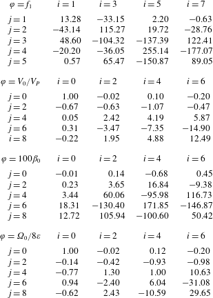
For the sake of completeness, polynomial fittings of the functions (3.9) are given in appendix C for both rigid and stress-free interfaces.
For sufficiently large
 $Re$
, the solution (3.9) is no longer valid, as we observe in figure 9, where the balanced body force is depicted versus the transverse position for various Reynolds numbers for a bubble with diameter
 $d=0.4$
in the case of bubbles with rigid interface and the pure nonlinear inertial regime. The behaviour remains qualitatively similar to the pure linear inertial migration.
The influence of the Reynolds number on the balanced body force for bubbles of size
 $d=0.4$
with a rigid interface in the pure nonlinear inertial regime.

The validity of the pure linear inertial regime,
 $Re<Re_{\ast }$
, can be quantified as follows with two different criteria depicted in figure 10. On the one hand, in figure 10(a,c), we plot the influence of the Reynolds number and the bubble size on the stability of the centred position given by
 $\unicode[STIX]{x2202}_{\unicode[STIX]{x1D700}}f/Re|_{\unicode[STIX]{x1D700}=0}$
. It can be observed that the range of validity of small
 $Re$
is slightly larger for bubbles with stress-free interface than with rigid one. The variation of the slope is referred to the one of the linear regime and normalised by the value of the latter for bubbles of size
 $d=0.3$
and
 $d=0.63$
for bubbles with rigid or stress-free interfaces respectively. These values correspond to local maxima of
 $\unicode[STIX]{x2202}_{\unicode[STIX]{x1D700}}f/Re|_{\unicode[STIX]{x1D700}=0}$
versus
 $d$
. On the other hand, the equilibrium position of neutral bubbles is modified. In figure 10(b,d), we plot the influence of the Reynolds number on the equilibrium position of a neutral bubble of certain size, i.e. in the absence of body force. The nonlinear effect of the inertia turns out to be destabilising, in general, either concerning the stability of the equilibrium, whose slope,
 $\unicode[STIX]{x2202}_{\unicode[STIX]{x1D700}}f$
, increases, or concerning the neutral bubble position, which is shifted away from the centre.
The influence of the Reynolds number and the size of a bubble with (a,b) a rigid or (c,d) a stress-free interface in pure nonlinear inertial regime for bubbles on (a,c) the slope of the balanced migration force exerted on centred bubbles with respect to the transverse position (– – – – –, stability transition) and (b,d) the equilibrium position of neutral bubbles. Not explored,

 $Re<Re_{\ast }(d)$
with
 $\cdots \cdots$
5 % error, – ⋅ – ⋅ – 2 % error and - - - - 1 % error.

3.2 Capillary migration
Migration forces may also arise if the bubble is deformable. In this case, the reversibility of the creeping flow is broken due to the antisymmetric deformation of the bubble. Indeed, the bubble deforms differently on its front and rear sides, due to pressure gradients of the creeping flow along the bubble surface. In figure 11, the deformation of the bubble due to the viscous and pressure forces exerted on its surface in the pure nonlinear capillary regime is depicted for given values of the transverse position and bubble size, whereas
 $Ca$
is varied. In particular, it can be observed that the overpressure (underpressure) for small
 $Ca$
deforms the bubble, locally decreasing (increasing) the curvature of the bubble surface, and the bubble deforms, as shown in figure 11. The capillary migration force exerted on the bubble surface always points towards the centre of the channel, as inferred from the dominant effect of the overpressure in figure 11(b,c).
Streamlines,
 $\boldsymbol{v}$
, and colourmap for the pressure field,
 $\hat{p}-x\unicode[STIX]{x2202}_{x}p_{P}$
, in the pure nonlinear capillary regime at the symmetry plane
 $z=0$
with bubble size
 $d=0.4$
centred at
 $\unicode[STIX]{x1D700}=0.7\unicode[STIX]{x1D700}_{\ast }$
and capillary numbers (a)
 $Ca=1/64$
, (b)
 $Ca=1/16$
and (c)
 $Ca=1/4$
.

The analogous role of
 $Ca$
in the pure capillary regimes, as compared with
 $Re$
in the pure inertial regimes, motivates an expansion of the system of equations (2.1)–(2.3), (2.5), (2.6) and (2.10) as
 $\unicode[STIX]{x1D713}=\sum _{j=0}^{\infty }Ca^{j}\unicode[STIX]{x1D713}_{j}$
, where
 $\unicode[STIX]{x1D713}$
represents any of the dependent variables
 $\hat{p}$
,
 $\boldsymbol{v}$
,
 $\boldsymbol{f}$
,
 $V$
or
 $\unicode[STIX]{x0394}p$
. In addition, the fact that for
 $Ca=0$
the dimensional pressure of the gas scales as
 $\unicode[STIX]{x1D6FE}/d$
motivates an expansion of the pressure of the gas,
 $p_{G}$
, starting from the minus first-order term, i.e.
 $p_{G}=\sum _{j=-1}^{\infty }Ca^{j}p_{Gj}$
.
The linearisation of the surface of the bubble
 $\unicode[STIX]{x1D6F4}_{B}$
is written as the displacement of the unperturbed surface
 $\unicode[STIX]{x1D6F4}_{B_{0}}$
in the normal direction by an infinitesimal amount
 $\unicode[STIX]{x1D6FF}$
, i.e.
 $\boldsymbol{x}=\boldsymbol{x}_{0}+\boldsymbol{n}\unicode[STIX]{x1D6FF}$
, where
 $\boldsymbol{x}_{0}\in \unicode[STIX]{x1D6F4}_{B_{0}}$
and
 $\boldsymbol{x}\in \unicode[STIX]{x1D6F4}_{B}$
. The fact that
 $\unicode[STIX]{x1D6FF}=0$
for
 $Ca=0$
motivates that its expansion starts from the first order,
 $\unicode[STIX]{x1D6FF}=\sum _{j=1}^{\infty }Ca^{j}\unicode[STIX]{x1D6FF}_{j}$
. In figure 12(a), we depict the unperturbed domain
 ${\mathcal{V}}_{0}$
with its bubble surface
 $\unicode[STIX]{x1D6F4}_{B_{0}}$
and their perturbed counterparts
 ${\mathcal{V}}$
and
 $\unicode[STIX]{x1D6F4}_{B}$
respectively. In figure 12(b), we schematise an infinitesimal portion of the perturbation volume, denoted by
 $\unicode[STIX]{x1D6F4}_{B_{0}}\unicode[STIX]{x1D6FF}$
, which is generated by the displacement
 $\unicode[STIX]{x1D6FF}\boldsymbol{n}_{0}$
of an infinitesimal surface lying on the unperturbed one,
 $\text{d}\unicode[STIX]{x1D6F4}_{B_{0}}$
, where subindex
 $0$
represents evaluation at the unperturbed surface. This volume is a truncated cone bounded by the infinitesimal surfaces lying on the unperturbed and perturbed surfaces, and the generatrix with outer normal vector
 $\unicode[STIX]{x1D6FF}\boldsymbol{n}_{S0}$
. The perturbed volume
 ${\mathcal{V}}$
is the junction of the unperturbed and perturbation ones, i.e.
 ${\mathcal{V}}\equiv {\mathcal{V}}_{0}\cup \unicode[STIX]{x1D6F4}_{B_{0}}\unicode[STIX]{x1D6FF}$
.
(a) Sketch of the unperturbed volume
 ${\mathcal{V}}_{0}$
bounded by the unperturbed surface
 $\unicode[STIX]{x1D6F4}_{B_{0}}$
and their perturbed counterparts
 ${\mathcal{V}}$
and
 $\unicode[STIX]{x1D6F4}_{B}$
. (b) Infinitesimal portion of the perturbation volume
 $\text{d}\unicode[STIX]{x1D6F4}_{B_{0}}\unicode[STIX]{x1D6FF}$
and its bounding boundaries. Subindex
 $0$
represents evaluation at the unperturbed surface, whereas the lack of it represents evaluation at the perturbed one.

Then, the linearisation of the Navier–Stokes equations (2.1), neglecting inertia,
 $Re=0$
, is written as
 $$\begin{eqnarray}\unicode[STIX]{x1D735}\boldsymbol{\cdot }\boldsymbol{v}_{0}=0,\quad \mathbf{0}=\unicode[STIX]{x1D735}\boldsymbol{\cdot }\hat{\unicode[STIX]{x1D749}}_{0}\quad \text{at }{\mathcal{V}}_{0},\end{eqnarray}$$
 $$\begin{eqnarray}\unicode[STIX]{x1D735}\boldsymbol{\cdot }\boldsymbol{v}_{1}=0,\quad \mathbf{0}=\unicode[STIX]{x1D735}\boldsymbol{\cdot }\hat{\unicode[STIX]{x1D749}}_{1}\quad \text{at }{\mathcal{V}}_{0}\end{eqnarray}$$
at the unperturbed volume
 ${\mathcal{V}}_{0}$
and, using the Stokes theorem and rearranging terms,
 $$\begin{eqnarray}\displaystyle \int _{\text{d}\unicode[STIX]{x1D6F4}_{B}}\boldsymbol{n}\boldsymbol{\cdot }\boldsymbol{v}\,\text{d}\unicode[STIX]{x1D6F4} & = & \displaystyle \int _{\text{d}\unicode[STIX]{x1D6F4}_{B_{0}}}(\boldsymbol{n}-\boldsymbol{D}_{S}\unicode[STIX]{x1D6FF})\boldsymbol{\cdot }\boldsymbol{v}\,\text{d}\unicode[STIX]{x1D6F4},\end{eqnarray}$$
 $$\begin{eqnarray}\displaystyle \int _{\text{d}\unicode[STIX]{x1D6F4}_{B}}\boldsymbol{n}\boldsymbol{\cdot }\hat{\unicode[STIX]{x1D749}}\,\text{d}\unicode[STIX]{x1D6F4} & = & \displaystyle \int _{\text{d}\unicode[STIX]{x1D6F4}_{B_{0}}}(\boldsymbol{n}-\boldsymbol{D}_{S}\unicode[STIX]{x1D6FF})\boldsymbol{\cdot }\hat{\unicode[STIX]{x1D749}}\,\text{d}\unicode[STIX]{x1D6F4}\end{eqnarray}$$
 $\unicode[STIX]{x1D6F4}_{B_{0}}\unicode[STIX]{x1D6FF}$
, where
 $\boldsymbol{D}_{S}\boldsymbol{\cdot }\unicode[STIX]{x1D6FF}\boldsymbol{v}$
and
 $\boldsymbol{D}_{S}\boldsymbol{\cdot }\unicode[STIX]{x1D6FF}\hat{\unicode[STIX]{x1D749}}$
represent the terms due to the fluxes though the generatrix, which have been rewritten using (2.11). It is also necessary to consider the identity
 $\unicode[STIX]{x1D735}[p_{G}-\boldsymbol{f}\boldsymbol{\cdot }(\boldsymbol{x}-\unicode[STIX]{x1D73A})]+\boldsymbol{f}=0$
, which always holds. Its evaluation at the perturbation volume
 $\unicode[STIX]{x1D6F4}_{B_{0}}\unicode[STIX]{x1D6FF}$
is rearranged, using the Stokes theorem, as
 $$\begin{eqnarray}\int _{\text{d}\unicode[STIX]{x1D6F4}_{B}}\boldsymbol{n}[p_{G}-\boldsymbol{f}\boldsymbol{\cdot }(\boldsymbol{x}-\unicode[STIX]{x1D73A})]\,\text{d}\unicode[STIX]{x1D6F4}=\int _{\text{d}\unicode[STIX]{x1D6F4}_{B_{0}}}\{(\boldsymbol{n}-\boldsymbol{D}_{S}\unicode[STIX]{x1D6FF})[p_{G}-\boldsymbol{f}\boldsymbol{\cdot }(\boldsymbol{x}-\unicode[STIX]{x1D73A})]-\unicode[STIX]{x1D6FF}\boldsymbol{f}\}\,\text{d}\unicode[STIX]{x1D6F4}.\end{eqnarray}$$
Equations (2.2), (2.3), (2.5) and (2.6) are linearised as in the inertial migration case, (3.2), (3.3), (3.5) and (3.6), because the rest of the boundaries do not deform. However, the linearisation of the Young–Laplace equation (2.10a
) is applied on the perturbed boundary
 $\unicode[STIX]{x1D6F4}_{B}$
, and can be written on the unperturbed boundary with the help of (3.11) and (3.12) as well as with (D 4) for the surface tension term, whose details are given in appendix D, as
 $$\begin{eqnarray}\boldsymbol{n}\boldsymbol{\cdot }\unicode[STIX]{x27E6}\unicode[STIX]{x1D749}_{-1}\unicode[STIX]{x27E7}=\boldsymbol{D}_{S}1\quad \text{at }\unicode[STIX]{x1D6F4}_{B_{0}}\end{eqnarray}$$
for minus first order and
 $$\begin{eqnarray}\displaystyle \boldsymbol{n}\boldsymbol{\cdot }\unicode[STIX]{x27E6}\unicode[STIX]{x1D749}_{0}\unicode[STIX]{x27E7}-\boldsymbol{D}_{S}\boldsymbol{\cdot }(\unicode[STIX]{x1D6FF}_{1}\unicode[STIX]{x27E6}\unicode[STIX]{x1D749}_{-1}\unicode[STIX]{x27E7}) & = & \displaystyle \boldsymbol{D}_{S}\boldsymbol{\cdot }\{\unicode[STIX]{x1D717}_{1}{\mathcal{I}}_{S}-[\unicode[STIX]{x1D735}_{\!S}(\unicode[STIX]{x1D6FF}_{1}\boldsymbol{n})]^{\text{T}}\}\quad \text{at }\unicode[STIX]{x1D6F4}_{B_{0}},\qquad \qquad\end{eqnarray}$$
 $$\begin{eqnarray}\displaystyle \boldsymbol{n}\boldsymbol{\cdot }\unicode[STIX]{x27E6}\unicode[STIX]{x1D749}_{1}\unicode[STIX]{x27E7}-\boldsymbol{D}_{S}\boldsymbol{\cdot }(\unicode[STIX]{x1D6FF}_{2}\unicode[STIX]{x27E6}\unicode[STIX]{x1D749}_{-1}\unicode[STIX]{x27E7}+\unicode[STIX]{x1D6FF}_{1}\unicode[STIX]{x27E6}\unicode[STIX]{x1D749}_{0}\unicode[STIX]{x27E7})-\unicode[STIX]{x1D6FF}_{1}\boldsymbol{f}_{0} & = & \displaystyle \boldsymbol{D}_{S}\boldsymbol{\cdot }\{\unicode[STIX]{x1D717}_{2}{\mathcal{I}}_{S}-[\unicode[STIX]{x1D735}_{\!S}(\unicode[STIX]{x1D6FF}_{2}\boldsymbol{n})]^{\text{T}}\}\quad \text{at }\unicode[STIX]{x1D6F4}_{B_{0}}\qquad \qquad\end{eqnarray}$$
 $\boldsymbol{D}_{S}1$
is the surface mean curvature vector and
 $\unicode[STIX]{x1D717}_{j}=\unicode[STIX]{x1D735}_{\!S}\boldsymbol{\cdot }(\unicode[STIX]{x1D6FF}_{j}\boldsymbol{n})$
is the surface dilatation at
 $j$
th order. It should be noted that
 $\unicode[STIX]{x27E6}\unicode[STIX]{x1D749}_{-1}\unicode[STIX]{x27E7}=p_{G-1}{\mathcal{I}}$
. Similarly, the linearisation of the impermeability condition on the bubble surface (2.10b
) is written, using (3.11), as
 $$\begin{eqnarray}\displaystyle \boldsymbol{n}\boldsymbol{\cdot }\boldsymbol{v}_{0} & = & \displaystyle 0\quad \text{at }\unicode[STIX]{x1D6F4}_{B_{0}},\end{eqnarray}$$
 $$\begin{eqnarray}\displaystyle \boldsymbol{n}\boldsymbol{\cdot }\boldsymbol{v}_{1}-\boldsymbol{D}_{S}\boldsymbol{\cdot }(\unicode[STIX]{x1D6FF}_{1}\boldsymbol{v}_{0}) & = & \displaystyle 0\quad \text{at }\unicode[STIX]{x1D6F4}_{B_{0}}.\end{eqnarray}$$
The linearisation of the volume and the transverse position definitions (2.12) is written, with the help of the Reynolds transport theorem, as
 $$\begin{eqnarray}\displaystyle \int _{{\mathcal{V}}_{B_{0}}}\,\text{d}{\mathcal{V}} & = & \displaystyle {\mathcal{V}}_{B},\end{eqnarray}$$
 $$\begin{eqnarray}\displaystyle \int _{{\mathcal{V}}_{B_{0}}}(\boldsymbol{x}-\unicode[STIX]{x1D73A})\,\text{d}{\mathcal{V}} & = & \displaystyle \mathbf{0},\end{eqnarray}$$
 ${\mathcal{V}}_{B_{0}}$
is the domain occupied by the unperturbed bubble, and its perturbation
 $$\begin{eqnarray}\int _{\unicode[STIX]{x1D6F4}_{B_{0}}}\unicode[STIX]{x1D6FF}_{1}\,\text{d}\unicode[STIX]{x1D6F4}=0,\quad \int _{\unicode[STIX]{x1D6F4}_{B_{0}}}\unicode[STIX]{x1D6FF}_{2}\,\text{d}\unicode[STIX]{x1D6F4}=0,\end{eqnarray}$$
 $$\begin{eqnarray}\int _{\unicode[STIX]{x1D6F4}_{B_{0}}}\unicode[STIX]{x1D6FF}_{1}(\boldsymbol{x}-\unicode[STIX]{x1D73A})\,\text{d}\unicode[STIX]{x1D6F4}=\mathbf{0},\quad \int _{\unicode[STIX]{x1D6F4}_{B_{0}}}\unicode[STIX]{x1D6FF}_{2}(\boldsymbol{x}-\unicode[STIX]{x1D73A})\,\text{d}\unicode[STIX]{x1D6F4}=\mathbf{0}.\end{eqnarray}$$
Since
 $p_{G-1}$
is a global variable, the solution of (3.13) and (3.16) is a sphere of volume
 ${\mathcal{V}}_{B}$
and at a position
 $\unicode[STIX]{x1D73A}$
,
 $$\begin{eqnarray}p_{G-1}=\frac{4}{d},\quad \boldsymbol{x}_{0}=\unicode[STIX]{x1D73A}+\frac{d}{2}\boldsymbol{n},\end{eqnarray}$$
whose surface dilatation is
 $\unicode[STIX]{x1D717}_{j}=-4\unicode[STIX]{x1D6FF}_{j}/d$
.
Solutions of the system (3.2), (3.3), (3.5), (3.6), (3.10), (3.14), (3.15) and (3.17) for the balanced body force, bubble velocity and pressure correction factor are of the form, truncated at
 $O(Ca^{2})$
,
 $$\begin{eqnarray}f_{\unicode[STIX]{x1D6FE}}\equiv f/Ca\approx f_{1}(\unicode[STIX]{x1D700},d),\quad V\approx V_{0}(\unicode[STIX]{x1D700},d),\quad \unicode[STIX]{x1D6FD}\approx \unicode[STIX]{x1D6FD}_{0}(\unicode[STIX]{x1D700},d),\end{eqnarray}$$
where the removed terms have been found numerically to be vanishing, i.e.
 $f_{0}=V_{1}=\unicode[STIX]{x1D6FD}_{1}=0$
, as can be inferred from the symmetries and reversibilities of the flow. It can be observed that the capillary migration force comes from the first-order solution, whereas the velocity and pressure drop come from the leading-order creeping regime, analogous to the inertial migration case. Furthermore, the sum of the capillary terms of (3.14a
) only has a normal component, i.e.
 $$\begin{eqnarray}\boldsymbol{n}\times \{\boldsymbol{D}_{S}\boldsymbol{\cdot }[\unicode[STIX]{x1D6FF}_{1}\unicode[STIX]{x27E6}\unicode[STIX]{x1D749}_{-1}\unicode[STIX]{x27E7}+\unicode[STIX]{x1D717}_{1}{\mathcal{I}}_{S}-(\unicode[STIX]{x1D735}_{\!S}\unicode[STIX]{x1D6FF}_{1}\boldsymbol{n})^{\text{T}}]\}=\mathbf{0}.\end{eqnarray}$$
Thus, the zeroth order of the capillary regime is exactly the same as the zeroth order of the inertial regime with stress-free interface, since one can identify the capillary terms of the former as the reduced counterpart of the impermeable surface pressure
 $\hat{p}_{s}$
,
 $$\begin{eqnarray}-\boldsymbol{n}\hat{p}_{s}=\boldsymbol{D}_{S}\boldsymbol{\cdot }\{\unicode[STIX]{x1D6FF}_{1}\unicode[STIX]{x27E6}\unicode[STIX]{x1D749}_{-1}\unicode[STIX]{x27E7}+\unicode[STIX]{x1D717}_{1}{\mathcal{I}}_{S}-[\unicode[STIX]{x1D735}_{\!S}(\unicode[STIX]{x1D6FF}_{1}\boldsymbol{n})]^{\text{T}}\}.\end{eqnarray}$$
In figure 13, we depict solutions of the pure nonlinear capillary flow for several values of
 $Ca$
and its linear limit to which the nonlinear solution converges when
 $Ca$
is sufficiently small,
 $Ca<Ca_{\ast }$
; see figure 3. The dependence of the balanced body force, the velocity and the pressure drop on the transverse position is shown for a given bubble size. It can be observed that the capillary migration is always stabilising since
 $\unicode[STIX]{x2202}_{\unicode[STIX]{x1D700}}f<0$
, as shown in figure 13(a). We also observe that large deformations reduce bubble migration, increase the bubble velocity and reduce the associated pressure drop. In figure 13(b) and (c), the limit of the pure linear capillary regime reproduces the bubble velocity and the pressure drop for stress-free bubbles in zeroth-order creeping flow,
 $V_{0}$
and
 $\unicode[STIX]{x0394}p_{0}$
, the latter being negative for some conditions. Remarkably, in this case, the bubble is stable for these conditions and, therefore, the presence of a deformable bubble may reduce the pressure drop.
The effect of the deformability of a bubble with size
 $d=0.4$
and the transverse position in the pure nonlinear capillary regime on the (a) balanced body force, (b) bubble velocity and (c) pressure correction factor.

The dependence of the balanced body force on the bubble size
 $d$
and transverse position
 $\unicode[STIX]{x1D700}$
in the pure linear capillary regime is depicted in figure 14. Bubbles experience a stronger repulsion from the wall as they become closer to it either because of their size or because of their position. The velocity and pressure correction factors are the same as in the pure linear inertial regime with stress-free boundary conditions (figure 8
b,c). In effect, positions that reduce the pressure drop with respect to that of Poiseuille flow are stable in the pure linear capillary regime.
The effect of the transverse position
 $\unicode[STIX]{x1D700}$
and the size
 $d$
of a bubble in the pure linear capillary regime on the balanced body force. Not explored,

 $\unicode[STIX]{x1D700}=\unicode[STIX]{x1D700}_{\ast }$
, ——.

For the sake of completeness, polynomial fitting of the function
 $f_{1}$
(3.19) is given in appendix C, table 5.
The validity of the pure linear capillary regime is lost either for not sufficiently small capillary numbers, see figure 13(a), leading to large deformation all around the bubble, or for smaller capillary numbers if the gap between the bubble and the wall is too small, leading to an increase of the local stresses and, therefore, larger deformation in this region, whereas the rest of the bubble remains mainly spherical. The latter effect is shown in figure 15, where the behaviour of a bubble with
 $Ca=1/16$
is depicted. In figure 15(a), the bubble contour at the symmetry plane is plotted at different positions. The bubble remains almost spherical until the wall effect is noticeable for positions at which a liquid layer prevents the bubble from touching the wall by deforming it and drastically repelling it from the wall; see figure 15(b). It can be observed that since the bubble deforms, the centre of the bubble can get closer to the wall and hence its feasible range is
 $-(1/2)<\unicode[STIX]{x1D700}<(1/2)$
instead of that corresponding to undeformable bubbles,
 $-\unicode[STIX]{x1D700}_{\ast }<\unicode[STIX]{x1D700}<\unicode[STIX]{x1D700}_{\ast }$
. However, in these additional regions,
 $-(1/2)<\unicode[STIX]{x1D700}<-\unicode[STIX]{x1D700}_{\ast }$
and
 $\unicode[STIX]{x1D700}_{\ast }<\unicode[STIX]{x1D700}<1/2$
, nonlinear effects are always present and the linear regime is not only nonsensical but numerically impossible.
The effect of the transverse position (a) on the shape of bubbles at the symmetry plane
 $z=0$
and (b) on the balanced body force in the pure nonlinear capillary regime with
 $Ca=1/16$
for bubbles with size
 $d=0.4$
. Undeformed shape, – ⋅ – ⋅ –; deformed shape, ——; discrete values of
 $\unicode[STIX]{x1D700}/\unicode[STIX]{x1D700}_{\ast }$
plotted in (a),
 $\times$
.

Now, it remains to quantify the validity of the pure linear capillary regime. On the one hand, we avoid nonlinear effect due to the proximity of the wall and study centred bubbles. We depict the stability measurement of centred positions,
 $\unicode[STIX]{x2202}_{\unicode[STIX]{x1D700}}f/Ca|_{\unicode[STIX]{x1D700}=0}$
, and observe in figure 16(a) that the validity range strongly depends on the bubble size. In particular, the repulsion of the wall increases the stability and produces larger deformation, then decreasing the validity of the pure linear capillary regime to
 $\log _{2}Ca_{\ast }\approx 2{-}9d$
, with errors smaller than 1 % for the velocity and 2 % in the slope of the balanced migration force of centred bubbles. We also observe in figure 16(b) that bubbles travel faster when they are strongly deformed, and may eventually travel faster than the maximum velocity of the liquid, i.e. twice the mean flow. It can be observed that for
 $V\geqslant 2$
the recirculation disappears. A two variables fitting valid in the range
 $0<d<0.6$
is given in appendix C.
The influence of
 $Ca$
and the bubble size in the pure nonlinear capillary regime on the (a) slope of the balanced migration force exerted on centred bubbles (
 $\unicode[STIX]{x1D700}=0$
) with respect to the transverse position and (b) velocity of centred bubbles, ——
 $V=2$
. Not explored,

 $Ca<Ca_{\ast }(d)$
with
 $\cdots \cdots$
5 % error, – ⋅ – ⋅ – 2 % error and - - - - 1 % error.

On the other hand, we study the nonlinearities due to the proximity of the wall, and the bubble is locally deformed by the presence of the wall (figure 15
a). In figure 17, we depict the behaviour of the bubble at
 $\unicode[STIX]{x1D700}=\unicode[STIX]{x1D700}_{\ast }$
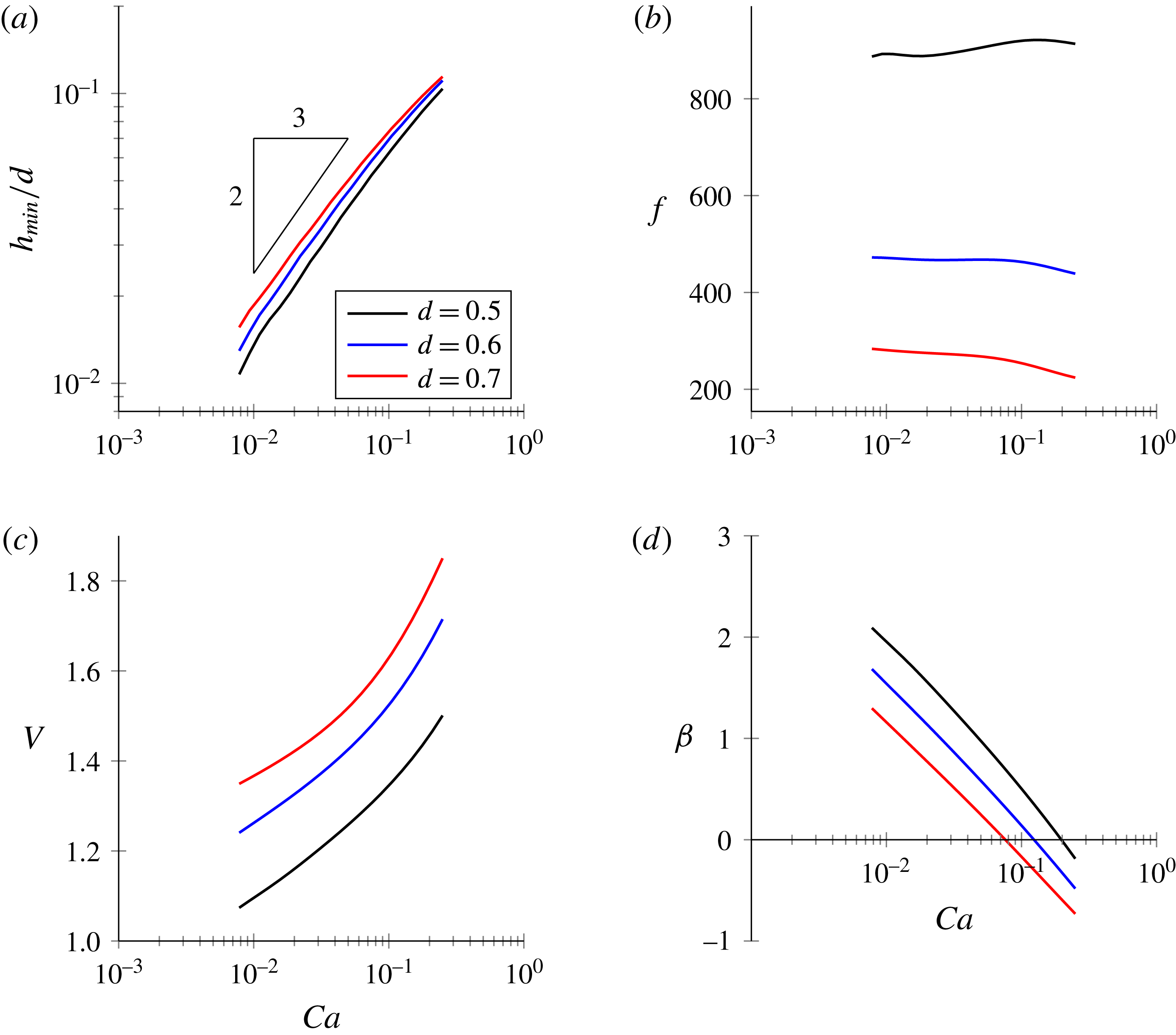
where the nonlinearities due to the proximity of the wall are dominant. The gap between the bubble and the wall follows the Landau–Levich
 $2/3$
power law at least for sufficiently small
 $Ca$
, as shown in figure 17(a). The balanced body force is not proportional to
 $Ca$
, in contrast to the pure linear capillary regime (figure 17
b); deformed bubbles travel faster as
 $Ca$
increases (figure 17
c) and the pressure drop decreases and can even take negative values (figure 17
d).
The influence of
 $Ca$
in the pure nonlinear capillary regime for a bubble centred at
 $\unicode[STIX]{x1D700}=\unicode[STIX]{x1D700}_{\ast }$
, where nonlinearities due to the proximity of the wall are dominant, on (a) the minimum gap between the wall and the bubble, (b) the balanced body force, (c) the bubble velocity and (d) the pressure correction factor.
3.3 Inertial versus capillary migration
We study the equilibrium position of a bubble when inertial and capillary migrations are taken into account as a function of
 $Re$
and
 $Ca$
and the bubble size
 $d$
in the linear regime. If we focus on a neutral bubble, the balanced body force
 $f\approx Re\,f_{\unicode[STIX]{x1D70C}}+Ca\,f_{\unicode[STIX]{x1D6FE}}$
must vanish at the equilibrium position, which then depends on the Ohnesorge number,
 $Oh^{2}=Ca/Re$
, instead of
 $Re$
and
 $Ca$
separately. In figure 18(a), we plot the uncentred and stable equilibrium position of a neutral bubble for a given value of
 $Oh$
. We observe that as
 $Oh\rightarrow 0$
, the equilibrium position tends to that of the pure linear inertial regime. In contrast, if
 $Oh$
becomes larger, the uncentred equilibrium position tends to get closer to the centre of the channel and eventually reaches the centre for sufficiently large values, as in the pure linear capillary regime. It can be observed that centred positions also exist, similarly to the pure inertial case, see figure 4(a), which corresponds to the centred branch of the pitchfork bifurcation, as illustrated in figure 8(a) for the pure linear inertial regime. In figure 18(b), we observe that there exist both a threshold on
 $Oh$
and a bubble size above which the centred position is always stable. This threshold also corresponds to
 $\unicode[STIX]{x2202}_{\unicode[STIX]{x1D700}}(Re\,f_{\unicode[STIX]{x1D70C}}+Ca\,f_{\unicode[STIX]{x1D6FE}})=0$
.
The influence of
 $Oh$
and the bubble size
 $d$
in the linear inertial–capillary regime. (a) Equilibrium position of neutral bubbles,
 $f=0$
, and (b) stability of centred positions. Not explored,

 $\unicode[STIX]{x1D700}=\unicode[STIX]{x1D700}_{\ast }$
, ——.

Next, we study the stability of the centred position as a function of
 $Oh$
and the bubble size
 $d$
in the nonlinear inertial–capillary regime. In figure 19, we depict the stability map for a few bubble sizes on the
 $Re$
–
 $Ca$
plane in both the linear and nonlinear inertial–capillary regimes, the latter considering interactions between inertial and capillary migration as well as the effects out of the linear inertial–capillary regime. The linear inertial–capillary regime is recovered for
 $Re<Re_{\ast }\approx 8$
, whereas the nonlinear effects are strongly stabilising above the threshold
 $Re>Re_{\ast }\approx 8$
due to the joint effect with capillary deformation. In particular, there exists for each bubble size a value of
 $Ca$
depending on the bubble size,
 $Ca_{c}(d)$
, above which centred bubbles are always stable, regardless of the value of
 $Re$
, i.e. the destabilising effect of inertia is overcome by the stabilising effect of the additional deformation of the bubble interface due to the effect of inertia. On the contrary, for values of
 $Ca$
smaller than
 $Ca_{c}$
, a range of
 $Re$
is found for which bubbles are unstable.
Stability diagram for centred bubbles in - - - - the linear and —— the nonlinear inertial–capillary regime.

4 Conclusions and discussion
This paper reports the dynamics of a train of bubbles regarding the flow structure and the migration forces of both inertial and capillary deformation origin. We write the general equations governing the dynamics of a train of bubbles. We assume the change of bubble size along the channel (due to gas dissolution for instance) to be slow compared with the characteristic hydrodynamic time, in which a bubble covers its own size, and that no turbulence develops. Under these assumptions, the flow can be considered to be quasistationary and time dependence can be dropped out. We quantitatively study the influence of the bubble size and of the body force on the linear inertial and capillary regimes. To do this, regular asymptotic expansions of the governing equations are carried out, including the linearisation of the boundary conditions of the deformable bubble surface around the undeformed shape, for which we provide a new asymptotical approach. Then, we compare with the nonlinear regimes governed by the full system of equations, using the ALE method for deformable bubbles, in order to obtain the validity of the linear regimes for
 $Re$
and
 $Ca$
.
In the case of pure inertial migration, we report the well-known multiple equilibrium behaviour and we illustrate the underlying hydrodynamic mechanism regarding the first-order pressure field correction of the creeping flow. Then, we describe the influence of the bubble size and the transverse equilibrium position on the external uniform body force that balances the migration force, the bubble velocity, the additional pressure drop (pressure correction factor) due to the presence of the bubble and the rotational velocity (only applicable in the case of bubbles with rigid interface). Since the external body force is commonly given, first, the position of the bubble has to be obtained to ensure the transverse equilibrium. Once the equilibrium position has been obtained, the velocity, additional pressure drop and rotation of the bubble (if applicable) can be obtained. In agreement with previous results, a small bubble follows the Poiseuille flow and a neutral bubble (in the absence of body force) migrates to the position at which the velocity of the Poiseuille flow and the mean velocity coincide, i.e. at
 $\unicode[STIX]{x1D700}=\sqrt{2}/4$
in the case of bubbles with rigid or stress-free interfaces. We also observe that the surface average of the Poiseuille velocity provides a reasonably good approximation of the bubble velocity for rigid interfaces. We observe that a neutral bubble with stress-free interface and a size smaller than
 $d\lesssim 0.85$
migrates out of the centre and within the range
 $0.35\lesssim d\lesssim 0.83$
migrates to the wall, i.e. to
 $\unicode[STIX]{x1D700}>0.95\unicode[STIX]{x1D700}_{\ast }$
where
 $\unicode[STIX]{x1D700}_{\ast }=(1-d)/2$
. A bubble with a rigid interface and with size smaller than
 $d\lesssim 0.73$
migrates to an intermediate position. We also observe that the presence of bubbles may reduce the pressure drop along the channel. However, this region is unstable due to inertial migration forces, but it may be stabilised by capillary migration forces. A plug effect is observed for bubbles with rigid interface, which dramatically increases the pressure drop with the bubble size. Small bubbles with rigid interface tend to rotate with the same rotational velocity as the Poiseuille flow as the bubble size decreases. Finally, we study the validity of the linear inertial regime and obtain a criterion based on the stability of the centred position and the equilibrium position of neutral bubbles. In both cases of rigid and stress-free bubble interfaces, nonlinearities break the validity of the linear regime for
 $Re$
larger than the approximate threshold
 $Re_{\ast }\approx 8$
as well as shifting the equilibrium position towards the wall.
Additionally, we consider the behaviour of deformable bubbles. In this case, underpressure and overpressure of the creeping flow on the bubble surface make it deform, leading to stabilising forces pointing towards the centre of the channel. We obtain the regular asymptotic expansion of the governing equations for small values of
 $Ca$
. Since the boundary of the domain at the bubble surface deforms, it is necessary to linearise the boundary conditions applied at this boundary around the undeformed shape. We observe that larger bubbles balance larger outer forces at the same equilibrium position, and this effect dramatically increases as the bubble approaches the wall due to either larger bubble size or transverse position. The linear capillary limit is valid for centred bubbles if the
 $Ca$
number is smaller than the approximate threshold
 $Ca<Ca_{\ast }\approx 2^{2-9d}$
, which decreases with the transverse position until it is no longer valid for an undeformed bubble touching the wall. In this case, a thin lubrication layer forms between the wall and the bubble due to the deformation of the latter. The minimum film thickness follows the
 $2/3$
Landau–Levich power law for
 $Ca<0.1$
, the migration force very slightly depends on the surface tension (no longer proportional to
 $Ca$
) and the bubble velocity increases with its deformation while the pressure drop decreases and can even reach negative values. Polynomial fittings are obtained for both the inertial and capillary linear regimes.
Finally, we obtain the transverse equilibrium position of neutral bubbles and the stability of the centred position (for neutral bubbles) taking into account both inertia and deformability. We obtain a stability diagram depending on
 $Oh=\sqrt{Ca/Re}$
and the bubble size in the pure linear inertial–capillary regime. We observe that centred solutions are stable for either
 $Oh$
larger than
 $Oh>0.2$
or for bubbles larger than
 $0.85\lesssim d$
, with a smooth transition between the two limits. We also observe that the nonlinear effects are no longer negligible for
 $Re$
larger than
 $Re_{\ast }\approx 8$
, above which nonlinear inertial–capillary effects become stabilising even for given
 $Ca$
, in contrast to what is observed in the pure nonlinear inertial regime.
The dynamics of drops in microchannels is of great interest in the scientific community, and this work implicitly explores the limiting cases of very high/low-viscosity drops. In particular, on the one hand, low-viscosity drops exhibit the same behaviour as capillary deformable bubbles. On the other hand, spherical high-viscosity drops and particles exhibit the same behaviour as spherical bubbles with rigid interface. However, the transition of the dynamics for the viscosity of the drop, i.e. for intermediate viscosities, is still to be systematically studied.
We also provide an approach for the linearisation of the boundary conditions around the equilibrium position of a deformable boundary, which relies on the external surface differential operator. This approach provides a powerful and simple theoretical background for other applications relying on deformable boundaries in complex geometries, such as global stability analysis of free interfaces in the most general conditions. The validity of the proposed method has been checked by comparison with the full nonlinear equations.
Acknowledgements
We thank B. Haut, D. Mikaelian and M. Pérez-Saborid for useful discussions. We thank the Brussels region for the financial support of this project through the WBGreen-MicroEco project. B.S. thanks the F.R.S.-FNRS for financial support as well as the IAP-7/38 MicroMAST project for supporting this research. This work was also performed under the umbrella of COST Action MP1106.
Appendix A. Surface operator
In this appendix, we introduce the exterior differential operator, defined by the generalised Stokes theorem, and the nabla operator, defined in terms of directional derivatives. Both are defined by their application on a volume and a surface; see table 1 for the nomenclature. Herein, we derive the relationships relevant in this work and the reciprocity theorem for their FEM discretisation.
Differential operators.

First, the exterior differential operator
 $\boldsymbol{D}$
can be defined by the generalised Stokes theorem as
 $$\begin{eqnarray}\int _{{\mathcal{V}}}\boldsymbol{D}\unicode[STIX]{x1D711}\,\text{d}{\mathcal{V}}=\int _{\unicode[STIX]{x1D6F4}}\boldsymbol{n}\unicode[STIX]{x1D711}\,\text{d}\unicode[STIX]{x1D6F4},\end{eqnarray}$$
where
 ${\mathcal{V}}$
is the volume bounded by the surface
 $\unicode[STIX]{x1D6F4}$
with outer normal vector
 $\boldsymbol{n}$
, and
 $\unicode[STIX]{x1D711}$
can be any scalar, vectorial or tensorial variable. However, this expression is not useful as such for numerical computations. Its components in a certain basis are more convenient for these purposes. Let
 $\{\boldsymbol{e}_{i}\}_{i=1,2,3}$
be the Cartesian basis. The nabla operator
 $\unicode[STIX]{x1D735}$
is then defined, using Einstein notation, as
 $$\begin{eqnarray}\unicode[STIX]{x1D735}\unicode[STIX]{x1D711}=\boldsymbol{e}_{i}\unicode[STIX]{x2202}_{x_{i}}\unicode[STIX]{x1D711},\end{eqnarray}$$
where
 $x_{i}$
are the Cartesian coordinates and
 $\unicode[STIX]{x2202}_{x_{i}}\unicode[STIX]{x1D711}=\unicode[STIX]{x2202}_{\unicode[STIX]{x1D716}}\unicode[STIX]{x1D711}(\boldsymbol{x}+\unicode[STIX]{x1D716}\boldsymbol{e}_{i})$
is the directional derivative. Both volume differential operators are equivalent,
 $$\begin{eqnarray}\unicode[STIX]{x1D735}\unicode[STIX]{x1D711}\equiv \boldsymbol{D}\unicode[STIX]{x1D711}.\end{eqnarray}$$
Second, the exterior surface differential operator,
 $\boldsymbol{D}_{S}$
, defined on a surface sketched in figure 2, can be defined by
 $$\begin{eqnarray}\int _{\unicode[STIX]{x1D6F4}}\boldsymbol{D}_{S}\unicode[STIX]{x1D711}\,\text{d}\unicode[STIX]{x1D6F4}=\int _{\unicode[STIX]{x1D6E4}}\boldsymbol{n}_{S}\unicode[STIX]{x1D711}\,\text{d}\unicode[STIX]{x1D6E4},\end{eqnarray}$$
where
 $\boldsymbol{n}_{S}$
is the outer normal to the contour
 $\unicode[STIX]{x1D6E4}$
of the differential surface
 $\unicode[STIX]{x1D6F4}$
and contained in the subdomain, i.e.
 $\boldsymbol{n}\boldsymbol{\cdot }\boldsymbol{n}_{S}=0$
. The surface nabla operator
 $\unicode[STIX]{x1D735}_{S}$
is defined as
 $$\begin{eqnarray}\unicode[STIX]{x1D735}_{\!S}\unicode[STIX]{x1D711}(\boldsymbol{x})=\boldsymbol{e}_{i}\unicode[STIX]{x2202}_{Sx_{i}}\unicode[STIX]{x1D711}={\mathcal{I}}_{S}\boldsymbol{\cdot }\boldsymbol{e}_{i}\unicode[STIX]{x2202}_{x_{i}}\unicode[STIX]{x1D711},\end{eqnarray}$$
where
 $\unicode[STIX]{x2202}_{Sx_{i}}\unicode[STIX]{x1D711}=\unicode[STIX]{x2202}_{\unicode[STIX]{x1D716}}\unicode[STIX]{x1D711}(\boldsymbol{x}+\unicode[STIX]{x1D716}{\mathcal{I}}_{S}\boldsymbol{\cdot }\boldsymbol{e}_{i})$
is the directional derivative within the surface and
 ${\mathcal{I}}_{S}$
is the surface identity,
 ${\mathcal{I}}_{S}={\mathcal{I}}-\boldsymbol{n}\boldsymbol{n}$
.
The surface differential operators are related to the volume differential operators. In effect, the left-hand side of (A 4) multiplied by an infinitesimal distance
 $h$
is written as
 $$\begin{eqnarray}h\int _{\unicode[STIX]{x1D6F4}}\boldsymbol{D}_{S}\unicode[STIX]{x1D711}\,\text{d}\unicode[STIX]{x1D6F4}=\int _{{\mathcal{V}}_{\unicode[STIX]{x1D6F4}}}\boldsymbol{D}_{S}\unicode[STIX]{x1D711}\,\text{d}{\mathcal{V}},\end{eqnarray}$$
where in this case
 ${\mathcal{V}}_{\unicode[STIX]{x1D6F4}}$
is the truncated cone generated by a displacement of
 $\unicode[STIX]{x1D6F4}$
in the direction
 $\boldsymbol{n}$
and by amount
 $h$
. Similarly, the right-hand side of (A 4) multiplied by an infinitesimal distance
 $h$
, using
 $\boldsymbol{n}_{S}=\boldsymbol{n}_{S}\boldsymbol{\cdot }{\mathcal{I}}_{S}$
,
 $\boldsymbol{n}\boldsymbol{\cdot }{\mathcal{I}}_{S}=\mathbf{0}$
and (A 1), and conveniently adding vanishing terms, yields
 $$\begin{eqnarray}h\int _{\unicode[STIX]{x1D6E4}}\boldsymbol{n}_{S}\boldsymbol{\cdot }{\mathcal{I}}_{S}\unicode[STIX]{x1D711}\,\text{d}\unicode[STIX]{x1D6E4}\pm \int _{\unicode[STIX]{x1D6F4}}\boldsymbol{n}\boldsymbol{\cdot }{\mathcal{I}}_{S}\unicode[STIX]{x1D711}\left(\boldsymbol{x}\pm \frac{1}{2}h\boldsymbol{n}\right)\,\text{d}\unicode[STIX]{x1D6F4}=\int _{{\mathcal{V}}_{\unicode[STIX]{x1D6F4}}}\unicode[STIX]{x1D735}\boldsymbol{\cdot }({\mathcal{I}}_{S}\unicode[STIX]{x1D711})\,\text{d}{\mathcal{V}},\end{eqnarray}$$
where the first term of the left-hand side represents the flux through the generatrix and the second integral represents the flux through the top and bottom bases of the truncated cone. It should be noted that (A 7) is independent of the value of
 $\unicode[STIX]{x1D711}$
outside the surface
 $\unicode[STIX]{x1D6F4}$
, or equivalently its normal gradient
 $\boldsymbol{n}\boldsymbol{\cdot }\unicode[STIX]{x1D735}\unicode[STIX]{x1D711}$
, which might even not be defined.
 $$\begin{eqnarray}\boldsymbol{D}_{S}\unicode[STIX]{x1D711}=\unicode[STIX]{x1D735}\boldsymbol{\cdot }({\mathcal{I}}_{S}\unicode[STIX]{x1D711}),\end{eqnarray}$$
and provided from (A 5) that
 $$\begin{eqnarray}\unicode[STIX]{x1D735}_{\!S}\unicode[STIX]{x1D711}={\mathcal{I}}_{S}\boldsymbol{\cdot }\unicode[STIX]{x1D735}\unicode[STIX]{x1D711},\end{eqnarray}$$
the relation between the two surface operators is written as
 $$\begin{eqnarray}\boldsymbol{D}_{S}\unicode[STIX]{x1D711}=\unicode[STIX]{x1D735}_{\!S}\unicode[STIX]{x1D711}+(\unicode[STIX]{x1D735}\boldsymbol{\cdot }{\mathcal{I}}_{S})\unicode[STIX]{x1D711},\end{eqnarray}$$
where
 $\unicode[STIX]{x1D735}\boldsymbol{\cdot }{\mathcal{I}}_{S}=\boldsymbol{D}_{S}1$
is the surface mean curvature vector. An alternative to the previous relation that avoids the definition of the surface curvature consists of the reciprocal theorem. In effect, from (A 8) and (A 10), one obtains
 $$\begin{eqnarray}\unicode[STIX]{x1D713}\boldsymbol{D}_{S}\unicode[STIX]{x1D711}=\boldsymbol{D}_{S}(\unicode[STIX]{x1D711}\unicode[STIX]{x1D713})-(\unicode[STIX]{x1D735}_{\!S}\unicode[STIX]{x1D713})\unicode[STIX]{x1D711},\end{eqnarray}$$
where
 $\unicode[STIX]{x1D713}$
is a scalar. Integration of (A 11) on a surface
 $\unicode[STIX]{x1D6F4}$
with outer normal
 $\boldsymbol{n}_{S}$
to the contour
 $\unicode[STIX]{x1D6E4}$
leads to the reciprocal theorem on surfaces,
 $$\begin{eqnarray}\int _{\unicode[STIX]{x1D6F4}}\unicode[STIX]{x1D713}\boldsymbol{D}_{S}\unicode[STIX]{x1D711}\,\text{d}\unicode[STIX]{x1D6F4}=\int _{\unicode[STIX]{x1D6E4}}\boldsymbol{n}_{S}(\unicode[STIX]{x1D711}\unicode[STIX]{x1D713})\,\text{d}\unicode[STIX]{x1D6E4}-\int _{\unicode[STIX]{x1D6F4}}(\unicode[STIX]{x1D735}_{\!S}\unicode[STIX]{x1D713})\unicode[STIX]{x1D711}\,\text{d}\unicode[STIX]{x1D6F4}.\end{eqnarray}$$
Expression (A 12) is appropriate to convert the
 $\boldsymbol{D}_{S}$
operator into the
 $\unicode[STIX]{x1D735}_{\!S}$
operator, in weak form; this is much more convenient for numerical simulations using the FEM since it is defined in terms of directional derivatives.
Appendix B. Reversibilities and symmetries
Zeroth-order creeping flow, denoted with subindex
 $0$
, is reversible. In effect, if we change the direction of the mean flow,
 $$\begin{eqnarray}J\leftarrow -J,\end{eqnarray}$$
the reversed fields, denoted with the subindex
 $R$
, fulfil
 $$\begin{eqnarray}p_{0}(x,y,z)=-p_{R}(x,y,z),\quad \boldsymbol{v}_{0}(x,y,z)=-\boldsymbol{v}_{R}(x,y,z).\end{eqnarray}$$
Furthermore, if the geometry exhibits symmetry with respect to the plane
 $x=0$
, the flow is also antisymmetric with respect to this plane, namely
 $$\begin{eqnarray}p_{0}(x,y,z)=-p_{0}(-x,y,z),\quad \boldsymbol{v}_{0}(x,y,z)=-{\mathcal{S}}\boldsymbol{\cdot }\boldsymbol{v}_{0}(-x,y,z),\end{eqnarray}$$
where
 ${\mathcal{S}}=-\boldsymbol{e}_{x}\boldsymbol{e}_{x}+\boldsymbol{e}_{y}\boldsymbol{e}_{y}+\boldsymbol{e}_{z}\boldsymbol{e}_{z}$
is the symmetry tensor with respect to the
 $x$
direction.
By evaluating expressions (B 3) at an arbitrary plane
 $x=h$
, dividing by
 $h$
and evaluating the limit when
 $h\rightarrow 0$
, we obtain the symmetry conditions
 $$\begin{eqnarray}p(0,y,z)=0,\quad \unicode[STIX]{x2202}_{x}\boldsymbol{v}(0,y,z)\boldsymbol{\cdot }\boldsymbol{e}_{x}=0,\quad \boldsymbol{v}(0,y,z)\boldsymbol{\cdot }\boldsymbol{e}_{y}=0,\quad \boldsymbol{v}(0,y,z)\boldsymbol{\cdot }\boldsymbol{e}_{z}=0.~~\end{eqnarray}$$
Now, pure linear inertial or capillary corrections of the creeping flow, denoted by the subindex
 $1$
, are antireversible. The change of direction of the mean flow (B 1) does not affect the linear correction since all non-homogeneous terms in the governing equations are quadratic in the creeping fields,
 $\hat{p}_{0}$
,
 $\boldsymbol{v}_{0}$
and
 $\unicode[STIX]{x1D6FF}_{0}$
(if applicable), and all negative signs cancel. The antireversibility character is described by
 $$\begin{eqnarray}p_{1}(x,y,z)=p_{AR}(x,y,z),\quad \boldsymbol{v}_{1}(x,y,z)=\boldsymbol{v}_{AR}(x,y,z),\end{eqnarray}$$
where subindex
 $AR$
refers to antireversible. In symmetric geometries, antireversible flows are also symmetric and fulfil
 $$\begin{eqnarray}p_{1}(x,y,z)=p_{1}(-x,y,z),\quad \boldsymbol{v}_{1}(x,y,z)={\mathcal{S}}\boldsymbol{\cdot }\boldsymbol{v}_{1}(-x,y,z).\end{eqnarray}$$
The limit
 $h\rightarrow 0$
of the evaluation of (B 6) at the arbitrary plane
 $x=h$
divided by
 $h$
leads to the antisymmetry conditions
 $$\begin{eqnarray}\unicode[STIX]{x2202}_{x}p(0,y,z)=0,\quad \boldsymbol{v}(0,y,z)\boldsymbol{\cdot }\boldsymbol{e}_{x}=0,\quad \unicode[STIX]{x2202}_{x}\boldsymbol{v}(0,y,z)\boldsymbol{\cdot }\boldsymbol{e}_{y}=0,\quad \unicode[STIX]{x2202}_{x}\boldsymbol{v}(0,y,z)\boldsymbol{\cdot }\boldsymbol{e}_{z}=0.\end{eqnarray}$$
Streamlines and pressure field at the
 $z=0$
symmetry plane (a) of the antisymmetric and reversible flow
 $\hat{p}_{0}$
and
 $\boldsymbol{v}_{0}$
and (b) of the symmetric and antireversible flow
 $\hat{p_{1}}$
and
 $\boldsymbol{v}_{1}$
for a centred bubble of size
 $d=0.4$
and with a rigid interface.

Reversibilities and symmetries for the considered regimes: S, symmetric; AS, antisymmetric; R, reversible; AR, antireversible.

Examples of both kinds of flows are depicted in figure 20. In table 2, the symmetries and reversibilities are tabulated. The zeroth-order creeping flow, which is antisymmetric and reversible, is modified for small
 $Re$
and
 $Ca$
, i.e. at first order, with a symmetric and antireversible flow, whereas symmetries and reversibilities are broken for large
 $Re$
or
 $Ca$
.


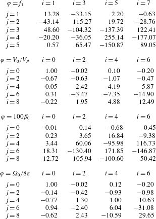
Appendix C. Fittings
In this appendix, we provide the coefficients of the polynomial fitting, with less than 1 % error within the range of parameters for which simulations have been carried out, of figures 7, 8 and 14 in the form
 $$\begin{eqnarray}\unicode[STIX]{x1D711}(d,\unicode[STIX]{x1D700})=\mathop{\sum }_{i}\mathop{\sum }_{j}\unicode[STIX]{x1D711}_{ij}\left(\frac{\unicode[STIX]{x1D700}}{\unicode[STIX]{x1D700}_{\ast }}\right)^{i}d^{j}\end{eqnarray}$$
in tables 3–5. In particular,
 $\unicode[STIX]{x1D711}$
represents the quantities
 $f_{1}$
,
 $V_{0}/V_{P}$
,
 $100\unicode[STIX]{x1D6FD}$
and
 $\unicode[STIX]{x1D6FA}_{0}/8\unicode[STIX]{x1D700}$
, where
 $V_{P}$
is the velocity of the Poiseuille flow,
 $V_{P}(\unicode[STIX]{x1D700})=2(1-4\unicode[STIX]{x1D700}^{2})$
. It can be observed that
 $(\unicode[STIX]{x1D700}/\unicode[STIX]{x1D700}_{\ast })^{0}=1$
, even for
 $\unicode[STIX]{x1D700}=0$
.


In addition, the fitting of the velocity of centred bubbles in the nonlinear capillary regime, plotted in figure 16(b), is also given as a correction of the linear capillary regime. It is written as
 $$\begin{eqnarray}V=2(1+0.02d^{2}-0.32d^{4}-1.05d^{6}+0.94d^{8})+{\textstyle \frac{1}{2}}+{\textstyle \frac{1}{2}}\operatorname{erf}[4(d+0.145\log Ca-0.68)],\end{eqnarray}$$
for
 $d<0.6$
and
 $Ca<1$
, where errors in the velocity of the bubble are smaller than 0.02, and the largest increase of velocity due to the deformability of the bubble is around
 $0.7$
.
Appendix D. Linearisation of surface tension
For the linearisation of the surface tension, we need to linearise the exterior differential operator
 $\boldsymbol{D}_{S}$
. For this purpose, we linearise the right-hand side of (2.11),
 $$\begin{eqnarray}\displaystyle \int _{\unicode[STIX]{x1D6E4}}\boldsymbol{n}_{S}\unicode[STIX]{x1D711}\,\text{d}\unicode[STIX]{x1D6E4}=\int _{\unicode[STIX]{x1D6E4}_{0}}\boldsymbol{n}_{S}\unicode[STIX]{x1D711}\,\text{d}\unicode[STIX]{x1D6E4}+\int _{\unicode[STIX]{x1D6E4}_{0}}\unicode[STIX]{x0394}(\boldsymbol{n}_{S}\unicode[STIX]{x1D711}\,\text{d}\unicode[STIX]{x1D6E4}), & & \displaystyle\end{eqnarray}$$
where
 $\unicode[STIX]{x0394}(\boldsymbol{n}_{S}\unicode[STIX]{x1D711}\,\text{d}\unicode[STIX]{x1D6E4})$
is the variation of
 $\boldsymbol{n}_{S}\unicode[STIX]{x1D711}\,\text{d}\unicode[STIX]{x1D6E4}$
between
 $\unicode[STIX]{x1D6E4}$
and
 $\unicode[STIX]{x1D6E4}_{0}$
for which Leibniz’s rule holds. The variation of
 $\unicode[STIX]{x1D711}$
vanishes for variables defined only on the surface, whereas the variation of
 $\boldsymbol{n}_{S}\text{d}\unicode[STIX]{x1D6E4}$
is obtained as follows. Let
 $\text{d}\boldsymbol{x}$
be an arbitrary vector on the surface with origin on
 $\unicode[STIX]{x1D6E4}_{0}$
. Thus, the variation of a surface element,
 $\text{d}\boldsymbol{x}\boldsymbol{\cdot }\boldsymbol{n}_{S}\text{d}\unicode[STIX]{x1D6E4}$
is written as (Pereira & Kalliadasis Reference Pereira and Kalliadasis2008)
 $$\begin{eqnarray}\unicode[STIX]{x0394}(\text{d}\boldsymbol{x}\boldsymbol{\cdot }\boldsymbol{n}_{S}\text{d}\unicode[STIX]{x1D6E4})=\unicode[STIX]{x0394}(\text{d}\boldsymbol{x})\boldsymbol{\cdot }\boldsymbol{n}_{S}\text{d}\unicode[STIX]{x1D6E4}+\text{d}\boldsymbol{x}\boldsymbol{\cdot }\unicode[STIX]{x0394}(\boldsymbol{n}_{S}\text{d}\unicode[STIX]{x1D6E4}),\end{eqnarray}$$
and therefore
 $$\begin{eqnarray}\unicode[STIX]{x1D717}\,\text{d}\boldsymbol{x}\boldsymbol{\cdot }\boldsymbol{n}_{S}\,\text{d}\unicode[STIX]{x1D6E4}=\text{d}\boldsymbol{x}\boldsymbol{\cdot }\unicode[STIX]{x1D735}_{\!S}(\unicode[STIX]{x1D6FF}\boldsymbol{n})\boldsymbol{\cdot }\boldsymbol{n}_{S}\,\text{d}\unicode[STIX]{x1D6E4}+\text{d}\boldsymbol{x}\boldsymbol{\cdot }\unicode[STIX]{x0394}(\boldsymbol{n}_{S}\,\text{d}\unicode[STIX]{x1D6E4}),\end{eqnarray}$$
where the surface dilatation
 $\unicode[STIX]{x1D717}=\unicode[STIX]{x1D735}_{\!S}\boldsymbol{\cdot }(\unicode[STIX]{x1D6FF}\boldsymbol{n})$
represents the variation of the surface elements and
 $\text{d}\boldsymbol{x}\boldsymbol{\cdot }\unicode[STIX]{x1D735}_{\!S}(\unicode[STIX]{x1D6FF}\boldsymbol{n})$
represents the variation of the arbitrary vector
 $\text{d}\boldsymbol{x}$
. Thus, using (D 1) and (D 3) for arbitrary
 $\text{d}\boldsymbol{x}$
, (2.11) is written as
 $$\begin{eqnarray}\displaystyle \int _{\unicode[STIX]{x1D6F4}}\boldsymbol{D}_{S}\unicode[STIX]{x1D711}\,\text{d}\unicode[STIX]{x1D6F4}=\int _{\unicode[STIX]{x1D6F4}_{0}}\boldsymbol{D}_{S}\boldsymbol{\cdot }[(1+\unicode[STIX]{x1D717}){\mathcal{I}}-(\unicode[STIX]{x1D735}_{\!S}\unicode[STIX]{x1D6FF}\boldsymbol{n})^{\text{T}}]\unicode[STIX]{x1D711}\,\text{d}\unicode[STIX]{x1D6F4}. & & \displaystyle\end{eqnarray}$$
After some algebraic manipulation, using the vector triple product and
 $\boldsymbol{n}\boldsymbol{\cdot }\boldsymbol{n}_{S}=0$
, one obtains that the variation of the curve element is due to the dilatation of the contour and due to the rotation of the surface, respectively represented by the terms of the right-hand side,
 $$\begin{eqnarray}\boldsymbol{n}_{S}\boldsymbol{\cdot }[\unicode[STIX]{x1D717}{\mathcal{I}}_{S}-(\unicode[STIX]{x1D735}_{\!S}\unicode[STIX]{x1D6FF}\boldsymbol{n})^{\text{T}}]=\boldsymbol{n}_{S}\boldsymbol{\cdot }(\unicode[STIX]{x1D717}{\mathcal{I}}_{S}-\unicode[STIX]{x1D6FF}\unicode[STIX]{x1D735}_{\!S}\boldsymbol{n})-\boldsymbol{n}_{S}\times [\unicode[STIX]{x1D735}_{\!S}\times (\unicode[STIX]{x1D6FF}\boldsymbol{n})].\end{eqnarray}$$