Introduction
For body-worn devices, the integration of polarization diversity is quintessential as it configures the antenna elements with a diverse sense of polarization to reduce the multipath interference and improve the system capacity and link reliability [Reference Khan, Capobianco, Naqvi, Ijaz, Asif and Braaten1]. The incorporation of multi-polarization on single electronic hardware reduces the number of antenna elements thereby reducing the overall antenna size. Generally, the polarization can be categorized as linear, circular, and elliptical polarization depending on the propagating direction. Linear polarized antenna provides RF radiation confined to a single plane either in a horizontal or vertical orientation along the direction of antenna propagation [Reference Adamiuk, Beer, Wiesbeck and Zwick2]. This provides better signal propagation between the antennas through the direct communication link (line of sight (LOS)). Thus, the linear polarized antenna can be utilized for direct information exchange between the body-worn devices positioned on a single plane [Reference Zhu, Guo and Wu3]. The benefits of circular polarization (CP) for indirect communication links (non-line of sight (NLOS)) are providing enormous features such as reducing the multipath interferences, polarization mismatch losses, and improving link reliability between the sensor nodes [Reference Kashif Nisar, Sharul Kamal, Ping Jack, Muhammad Ramlee, Kim-Geok, Yew Chiong and Mohammad Tariqul4]. A circular polarized antenna could be designed if the phase difference between the electric field vectors is orthogonal to each other [Reference Tran, Nguyen-Trong and Abbosh5].
The most commonly used techniques for achieving CP are through the feeding mechanism [Reference Sun6, Reference Narbudowicz, Sipal, Bao and Ammann7] and array antenna [Reference Xu, Gao, Liu, Li, Luo, Hu, Wen, Yang and Sri Sumantyo8] which results in the tedious electronic platform. A differential fed circular polarized microstrip patch antenna [Reference Sun6] is reported which covers the ultra-wideband (UWB) resonance using a combination of multiple resonance modes. A dual-fed slot antenna [Reference Narbudowicz, Sipal, Bao and Ammann7] integrated with a phase shifter achieves the wideband resonance of 3.2–6.1 GHz. The incorporation of the differential feeding technique [Reference Sun6] and the phase shifter [Reference Narbudowicz, Sipal, Bao and Ammann7] increases the complexity of the antenna design. An asymmetric circular-arc-shaped monopole antenna element [Reference Xu, Gao, Liu, Li, Luo, Hu, Wen, Yang and Sri Sumantyo8] produces CP for the wideband frequency of 1.17–5.79 GHz. To overcome this, a single-fed circular polarized antenna is most preferred as it results in a simple structured antenna design thereby reducing the fabrication complexity and manufacturing cost. The incorporation of two separate semicircular slots in the single-fed broadband antenna [Reference Le, Tran and Park9] aids in achieving the CP utilizing the proximity coupling but the required UWB frequency range is not covered. The single-fed slot antenna designs [Reference Ding, Gao, Yu and Qu10, Reference Ullah and Koziel11] are applicable for a particular frequency range with a low gain value. Thus, achieving the CP for the entire UWB resonance in a single-fed antenna design is a challenging task.
To facilitate the signal transmission between the antennas for supporting both the LOS and NLOS communication link, the integration of MIMO antenna design with polarization diversity (both linear polarization and CP) is a quintessential feature of the upcoming wearable technology. A MIMO antenna [Reference Iqbal, Smida, Alazemi, Waly, Khaddaj Mallat and Kim12] achieves CP (both left-hand CP (LHCP) and right-hand CP (RHCP)) covering the range of 1.73–3.94 GHz but it is backed with an isolated ground plane which becomes unfavorable for use in practical applications. A co-planar waveguide (CPW)-fed monopole antenna [Reference Ullah, Mabrouk and Koziel13] induces CP (both LHCP and RHCP) covering the wideband of 5.2–6.3 GHz but the spacing between the antenna elements is greater than half wavelength which results in a larger antenna size. A slot antenna provides the orthogonal linear polarized field for the UWB applications [Reference Krishna and Kumar14] but it results in a low-efficiency value. Mutual coupling reduction between the 4 × 1 array of UWB antenna elements [Reference Dabas, Gangwar, Kanaujia and Gautam16] is reduced using a uniplanar EBG structure but the incorporation of EBG results in increased design complexity. Dual-polarized antenna is illustrated for the UWB frequency range [Reference Saxena, Kanaujia, Dwari, Kumar and Tiwari17] but the CP is achieved for the limited application bands such as Wi-Max and WLAN. MIMO antenna designed on a common coplanar ground [Reference Ullah, Al-Hasan, Koziel and Mabrouk18] generates CP but the required UWB frequency range is not covered and also it provides limited axial ratio (AR) bandwidth coverage. Therefore, the challenges faced in the design of MIMO antenna are bulky size [Reference Khan, Capobianco, Naqvi, Ijaz, Asif and Braaten1–Reference Kanagasabai, Sambandam, Alsath, Palaniswamy, Ravichandran and Girinathan21], dual-polarization either CP [Reference Iqbal, Smida, Alazemi, Waly, Khaddaj Mallat and Kim12, Reference Ullah, Mabrouk and Koziel13, Reference Saxena, Kanaujia, Dwari, Kumar and Tiwari17, Reference Ullah, Al-Hasan, Koziel and Mabrouk18] or LP [Reference Krishna and Kumar14, Reference Zhu, Li, Feng, Deng and Yin15], limited frequency range [Reference Iqbal, Smida, Alazemi, Waly, Khaddaj Mallat and Kim12–Reference Kanagasabai, Sambandam, Alsath, Palaniswamy, Ravichandran and Girinathan21], limited AR bandwidth coverage [Reference Xu, Gao, Liu, Li, Luo, Hu, Wen, Yang and Sri Sumantyo8–Reference Ding, Gao, Yu and Qu10, Reference Ullah and Koziel11, Reference Iqbal, Smida, Alazemi, Waly, Khaddaj Mallat and Kim12, Reference Saxena, Kanaujia, Dwari, Kumar and Tiwari17–Reference Kanagasabai, Sambandam, Alsath, Palaniswamy, Ravichandran and Girinathan21], and low gain and efficiency [Reference Ding, Gao, Yu and Qu10, Reference Ullah and Koziel11, Reference Krishna and Kumar14, Reference Veeraselvam, Mohammed, Savarimuthu, Marimuthu and Balasubramanian19]. Therefore, the MIMO antenna integrated with the polarization diversity technique should be designed capable of overcoming the polarization mismatch losses, the structural deformation effects, and body orientation variation which are most common in wearable applications. Thus, the multi-polarized MIMO UWB antenna designed with both CP (LHCP and RHCP) and linear polarization characteristics becomes most advantageous for WBAN application.
In this paper, a low-profile multi-polarized MIMO UWB antenna for body-centric communications is reported. The configuration of the MIMO antenna comprises the SHM antenna and a mirrored SHM antenna coupled with the CPW for providing linear polarization and an ARSM radiator and a mirrored ARSM antenna for providing CP. The radiating elements are positioned above a modified C-shaped ground plane (MCGP) to produce the multi-polarization characteristics over the entire ultra-wide bandwidth. The polarization diversity antenna achieves the omnidirectional radiation pattern with the required gain and efficiency suitable for practical applications. Section “Antenna design” elaborates on the operating principle, the evolving stages with simulated results, and the implementation of polarization diversity. Radiation parameters are simulated and measured on both free space and human body models and the detailed results are discussed in section “Results and discussions”. Section “MIMO performance analysis” explains the MIMO performance analysis.
Antenna design
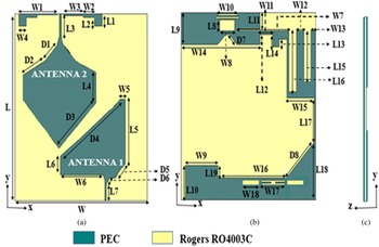
The dual-polarized MIMO UWB antenna is designed with a footprint of 38 × 35 × 0.2 mm3. The substrate utilized for the antenna design is a low-loss thin Rogers RO4003C material possessing a thickness of 0.2 mm, ɛr 3.55, and tanδ 0.0027. Two radiating monopoles such as an asymmetric ruby-shaped monopole (ARSM) antenna (CP antenna) and a symmetric heptagonal monopole (SHM) antenna (LP antenna) are assembled on a single substrate backed with an MCGP as shown in Fig. 1.
Geometry of the proposed antenna. (a) Front view, (b) rear view, and (c) side view dimensions of proposed antenna are L = 38; W = 35; L1 = 2; L2 = 1.25; L3 = 6.2; L4 = 6.2; L5 = 13; L6 = 3.8; L7 = 3.5; L8 = 2.2; L9 = 6.5; L10 = 7; L11 = 3.4; L12 = 2; L13 = 1.5; L14 = 2.4; L15 = 10.2; L16 = 12.4; L17 = 8.9; L18 = 11.8; L19 = 2.5; L20 = 0.9; W1 = 10.2; W2 = 2.9; W3 = 5.3; W4 = 2; W5 = 1.4; W6 = 11.4; W7 = 6; W8 = 4; W9 = 8.5; W10 = 5; W11 = 13.3; W12 = 2; W13 = 1.4; W14 = 20.5; W15 = 6.9; W16 = 17.9; W17 = 6; D1 = 4.6; D2 = 5.8; D3 = 13.3; D4 = 19.5; D5 = 3.8; D6 = 1.3; D7 = 2.8; D8 = 10.3 (all dimensions are in mm).

Evolution of CP antenna and mechanism
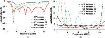
An asymmetrically fed rectangular monopole antenna is utilized (Fig. 2(a)) in which the fundamental mode is degenerated as two orthogonal modes with the aid of an L-shaped ground plane thereby generating the CP. This modification results in the impedance matching <6 dB for the UWB resonance with CP-AR <5 dB. The truncation of the monopole antenna results in the right-angled monopole antenna (Fig. 2(b)) leading to an impedance bandwidth of 4–4.5 GHz with CP-AR<3 dB with limited coverage of 7–9 GHz. The beveled edges are introduced on the lower right side of the monopole antenna resulting in the ARSM antenna and the truncation is incorporated in the ground plane resulting in the truncated ground plane (Fig. 2(c)). This modification plays a major role in altering the current distribution thereby improving CP-AR <3 dB in a wideband range of 4–10 GHz and the impedance bandwidth of 2.8–5 GHz. To achieve impedance matching <10 dB at the upper resonance range covering 2.8–10.6 GHz, the square stub is incorporated on the left side of the ground plane (Fig. 2(d)). For optimization, an I-shaped slot and square slots are inserted in the truncated ground plane (Fig. 2(e)) for sustaining the CP at the lowest and upper frequencies thereby covering CP-AR <3 dB in the required UWB resonance. Thus, the proposed antenna design generates the CP in the required UWB resonance band with AR <3 dB as shown in Fig. 3.
Evolution of the CP antenna. (a) CP antenna 1, (b) CP antenna 2, (c) CP antenna 3, (d) CP antenna 4, (e) CP antenna 5.

(a) Simulated reflection characteristics of CP antenna. (b) Axial ratio bandwidth of CP antenna.

Evolution of LP antenna
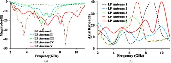
Initially, a square monopole antenna supported with a partial ground plane provides a narrow-band resonance at 3.5 GHz with linear polarization as shown in Fig. 4(a). A triangular-shaped stub (Fig. 4(b)) is added to the monopole antenna to realize good impedance matching covering 6–7 GHz with LP-AR >12 dB in the narrow range of 4.5–6.5 GHz. The truncation (Fig. 4(c)) is performed above the feedline of the monopole antenna to enhance the impedance bandwidth in the wideband range from 5 to 8 GHz along with LP-AR >10 dB for 4.5–8 GHz. CPW with the ground (Fig. 4(d)) is utilized to introduce the multiple resonance modes without affecting the polarization characteristics. The CPW is modified as a staircase-type structure to introduce the stepped impedance. The incorporation of a V-shaped slit in the partial ground plane backing the SHM radiator (Fig. 4(e)) provides an impedance matching <10 dB in the 3.5–5 GHz frequency range. A set of parallel thin slots are etched out from the partial ground plane to obtain better impedance matching in the entire UWB resonance band along with linear polarization characteristics as shown in Fig. 5.
Evolution of the LP antenna. (a) LP antenna 1, (b) LP antenna 2, (c) LP antenna 3, (d) LP antenna 4, (e) LP antenna 5.

(a) Simulated reflection characteristics of LP antenna. (b) Axial ratio bandwidth of LP antenna.

Surface current distribution
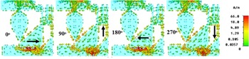
To better understand the polarization characteristics, the current distribution at the frequency of 6 GHz with different phase angles such as 0°, 90°, 180°, and 270° is simulated. From Fig. 6, it is observed that the current distribution is uniformly distributed in the SHM antenna (LP antenna) resulting in the linear polarization. Whereas the current path traces the anti-clockwise direction on ARSM antenna (CP antenna) from +X-direction for 0° phase, +Y-direction for 90° phase, –X-direction for 180° phase, and –Y-direction for 270° phase thereby resulting in the RHCP. Similarly, the antenna is mirror-imaged along the x-z axis providing LHCP [Reference Kanagasabai, Sambandam, Alsath, Palaniswamy, Ravichandran and Girinathan21].
Surface current distribution of the proposed antenna with different phase angles.

MIMO configuration and isolation mechanism
Multipath fading affects the antenna performance due to the scattering from the indoor objects and the human body movements in the highly-dense environment. MIMO technique with polarization diversity gives a promising solution to mitigate the multipath fading effect, overcome the polarization mismatch losses, and provide a high data rate, throughput, and channel capacity. The proposed antenna elements with diverse polarization characteristics are configured in a single platform. The diagonal opposite arrangement of the radiators as shown in Fig. 7 reduces the mutual coupling between them and provides isolation >10 dB. Further, the required isolation is achieved through the incorporation of rectangular slots in the MCGP. The reflection and isolation characteristics of the dual-polarized antenna provide simulated results as in Fig. 8. From the figure, it is inferred that the dual-polarized antenna design achieves good isolation >15 dB in the required UWB resonance band.
Proposed dual-polarized UWB antenna.

Simulated reflection and isolation characteristics of the dual-polarized UWB antenna.

To obtain multi-polarization characteristics, the monopole antenna elements are mirrored along the x-z axis resulting in a 2 × 2 MIMO antenna as represented in Fig. 9. The footprint of the 2 × 2 multi-polarized MIMO antenna is 38 × 70 × 0.2 mm3. This configuration consists of the ARSM antenna (antenna 1), a mirrored ARSM antenna (antenna 3), a SHM antenna (antenna 2), and a mirrored SHM antenna (antenna 4) on an MCGP. This results in multi-polarization characteristics such as dual linear polarization and CP (LHCP and RHCP). The 2 × 2 MIMO antenna provides an impedance matching <10 dB in the entire UWB resonance band which can be viewed in Fig. 10. The isolation between the monopole antenna elements (SHM, ARSM) and the mirrored monopole antenna elements is >15 dB using the insertion of a rectangular slot in the backed MCGP which can be viewed in Fig. 11. Increasing the number of antenna elements increases the throughput, data rate, and channel capacity.
Configuration of 2 × 2 multi-polarized MIMO antenna.

Simulated reflection characteristics of the 2 × 2 MIMO antenna.

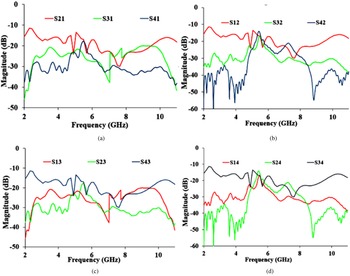
Simulated isolation characteristics of the 2 × 2 MIMO antenna. (a) Antenna 1 with respect to antennas 2, 3, and 4. (b) Antenna 2 with respect to antennas 1, 3, and 4. (c) Antenna 3 with respect to antennas 1, 2, and 4. (d) Antenna 4 with respect to antennas 1, 2, and 3.

Results and discussions
Figure 12 shows the fabricated prototype of the dual-polarized antenna. CST studio suite 2015 has been utilized for the simulation and the measurement using the E5071C Keysight Vector Network Analyzer.
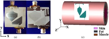
A fabricated prototype. (a) Front view, (b) rear view, (c) cylindrical human body model.

Reflection characteristics
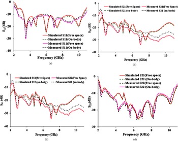
The simulated and measured impedance bandwidth for both the antenna elements in free space achieves the entire UWB resonance with better isolation >15 dB. To analyze the antenna performance for WBAN applications, the simulated cylindrical human body model is developed using stacked layers such as skin, fat, and muscle with distinct thickness, permittivity, and loss tangent using Table 1 [Reference Kanagasabai, Sambandam, Alsath, Palaniswamy, Ravichandran and Girinathan21] as depicted in Fig. 12(c). The measurement has experimented on the human arm including a height of 178 cm along with a weight of 70 kg. A 5 mm thick foam spacer separates the dual-polarized antenna design from the human body model. Thus, from Fig. 13 it is clearly understood that the simulated results are in good correlation with measured results. A slight difference is observed between the free space and on-body results due to the high conductivity of the body tissues even though the required reflection characteristics are obtained.
Simulated and measured reflection and isolation characteristics of the proposed antenna in free space and on-body. (a) S 11, (b) S 21, (c) S 12, (d) S 22.

Characterization of the cylindrical human body model at different frequencies

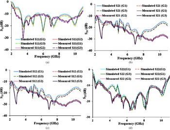
To analyze the on-body effects, the various distances (G) such as G1 = 3 mm, G2 = 5 mm, and G3 = 7 mm are maintained from the proposed antenna to the human body model in both simulation and measurement, and the obtained results are depicted in Fig. 14. Therefore, the dual-polarized antenna sustains its performance overcoming the on-body effects thereby becoming most preferable for WBAN applications.
Simulated and measured on-body results due to the varying gap between the antenna and the human body.

Radiation pattern
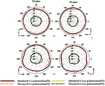
An anechoic chamber is utilized for the radiation pattern measurement. At the frequency of 4 GHz, the measured and simulated radiation pattern for the linear polarized antenna and the circularly polarized antenna is provided in Fig. 15 resulting in an omnidirectional radiation pattern.
Simulated and measured radiation pattern in free space at 4 GHz. (a) LP antenna, (b) CP antenna.

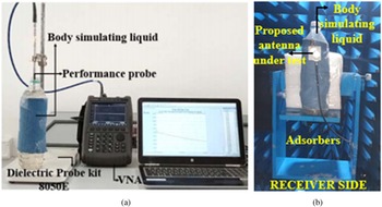
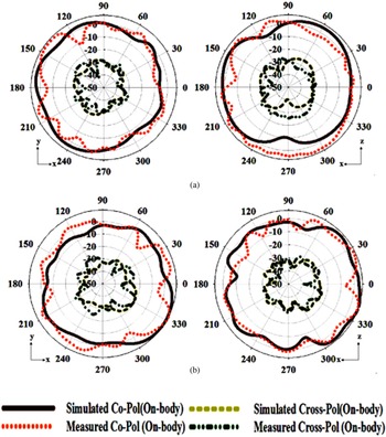
For on-body analysis, the simulated radiation pattern is attained by fixing the dual-polarized antenna over the cylindrical human body model as in Fig. 12(c). To measure an on-body radiation pattern, a plastic container is composed of a body mimicking liquid appropriate to a human arm with a radius of 30 mm. The composition of the body mimicking liquid is deionized water (60%) and sucrose (40%) [Reference Kanagasabai, Sambandam, Alsath, Palaniswamy, Ravichandran and Girinathan21]. To quantify the dielectric constant of the prepared combination, the dielectric probe kit, 8050E from Keysight is utilized as depicted in Fig. 16(a) and the performance probe is immersed into the plastic container. N9951A microwave analyzer is used for observing the reflection coefficient characteristics. From the reflection characteristics, the measured dielectric constant for the frequencies such as 3.1 and 5.8 GHz are provided in Table 2. The dual-polarized antenna along with a cloth is then wrapped over a body-mimicking liquid-filled plastic container. The measurement setup for analyzing the on-body radiation pattern is placed in an anechoic chamber as provided in Fig. 16(b). The omnidirectional radiation pattern obtained from on-body shows slight changes from the radiation pattern obtained from free space due to the presence of a partial ground plane as provided in Fig. 17. Even though the results obtained become preferable for body-centric communications.
(a) Dielectric constant measurement setup. (b) On-body radiation pattern measurement setup.

Comparison of the simulated and measured radiation pattern on-body at 4 GHz. (a) LP antenna, (b) CP antenna.

Properties of body mimicking model

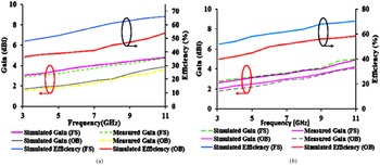
Figure 18 provides the dual-polarized antenna providing total efficiency and realized gain values. The simulated and measured gain in free space varies from 3.05–4.8/2.9–4.75 dBi to 2.8–5/2.65–4.9 dBic with the simulated total efficiency of 48–66% and 52–70.5% for linear and circular polarized antenna, respectively. For on-body, the simulated and measured gain varies from 1.7–3.9/1.55–3.65 dBi to 2–4.2/1.8–4.05 dBic with the simulated total efficiency of 36.5–54% and 40–58.5% for linear and circular polarized antenna, respectively. A partial ground plane backing the antenna elements results in the decreased values of gain and efficiency tested on-body when compared to free space values. Even though, the gain and efficiency values obtained from the dual-polarized antenna can be applicable for the real-time environment.
Comparison of gain and efficiency in free space and on-body. (a) Linear polarized antenna, (b) circular polarized antenna.

Specific absorption rate
The radiation exposure penetrating the body tissues is measured by using a parameter specific absorption rate (SAR). The maximum SAR value is acceptable up to 1.6 W/kg for 1 g of tissue in accordance with FCC standards. The SAR analysis is performed by placing the dual-polarized antenna above a simulated cylindrical body model as modeled in Fig. 12(c). The input power used for the analysis is 0.25 mW. A 5 mm foam spacer separates the dual-polarized antenna from the cylindrical body model. Thus, the simulated SAR values are observed as 0.736/0.982 W/kg for CP antenna (Antenna 1) and 0.692/0.956 W/kg for LP antenna (Antenna 2) at 6 and 8 GHz, respectively, whose values become most suited for real-time WBAN applications.
MIMO performance analysis
In MIMO antenna systems, the interaction between the adjacent antenna elements affects the overall efficiency and operating bandwidth. The envelope correlation coefficient (ECC) indicates the amount of correlation between the antenna elements. Practically, the value of ECC should be less than 0.1. From the far-field distribution given below, ECC is calculated.

The dual-polarized antenna provides the simulated ECC < 0.01 in the obtained UWB resonance band. The diversity gain (DG) deals with the analysis of improving signal integrity to a certain extent. The DG is calculated using,

The obtained simulated DG values are relatively around 10 dB in the entire UWB resonance band. Mean effective gain (MEG) is the measure of relative mean power levels from each radiator used for signal transfer. For a good diversity performance, the MEG ratio of two antenna elements should follow the criteria of |MEG1/MEG2| = 1. The MEG values of the dual-polarized antenna design are comparatively equal to 1.
The proposed antenna is developed with the following novel features such as
1. The dual-polarized antenna possesses a simple geometry, low profile, and lightweight thus it can be easily accompanied along with other electronic circuits unlike [Reference Khan, Capobianco, Naqvi, Ijaz, Asif and Braaten1–Reference Palaniswamy, Kanagasabai, Shrivastav, Sangeetha and Jayaram23].
2. MIMO antenna is developed on a thin, flexible, and low-cost dielectric substrate thereby reducing the cost of the overall system and enabling easy fabrication dissimilar to [Reference Khan, Capobianco, Naqvi, Ijaz, Asif and Braaten1–Reference Palaniswamy, Kanagasabai, Shrivastav, Sangeetha and Jayaram23].
3. The entire UWB resonance is achieved using simple techniques such as coplanar waveguide technology and resonance coupling dissimilar to [Reference Khan, Capobianco, Naqvi, Ijaz, Asif and Braaten1–Reference Palaniswamy, Kanagasabai, Shrivastav, Sangeetha and Jayaram23].
4. Good isolation characteristics are achieved in the entire UWB resonance band with a minimum inter-element spacing (less than λ/4) in contrast to [Reference Ullah, Mabrouk and Koziel13, Reference Krishna and Kumar14, Reference Dabas, Gangwar, Kanaujia and Gautam16, Reference Veeraselvam, Mohammed, Savarimuthu, Marimuthu and Balasubramanian19].
5. CP is achieved with a wide AR for the entire UWB frequency range using a single feed configuration and through simple techniques such as asymmetrical structure, truncation, and ground modification dissimilar to [Reference Khan, Capobianco, Naqvi, Ijaz, Asif and Braaten1–Reference Palaniswamy, Kanagasabai, Shrivastav, Sangeetha and Jayaram23].
6. A novel antenna system providing multi-polarization characteristics such as dual linear, LHCP, and RHCP is applicable for body-centric communication unlike [Reference Khan, Capobianco, Naqvi, Ijaz, Asif and Braaten1–Reference Palaniswamy, Kanagasabai, Shrivastav, Sangeetha and Jayaram23].
7. Unlike [Reference Ullah, Mabrouk and Koziel13, Reference Zhu, Li, Feng, Deng and Yin15, Reference Saxena, Kanaujia, Dwari, Kumar and Tiwari17–Reference Palaniswamy, Kanagasabai, Shrivastav, Sangeetha and Jayaram23], the dual-polarized antenna provides a stable considerable gain and efficiency in a small aperture area suitable for real-time WBAN applications.
8. The simulated SAR values are limited following the FCC standards in contrast to [Reference Khan, Capobianco, Naqvi, Ijaz, Asif and Braaten1–Reference Zhu, Li, Feng, Deng and Yin15, Reference Saxena, Kanaujia, Dwari, Kumar and Tiwari17–Reference Palaniswamy, Kanagasabai, Shrivastav, Sangeetha and Jayaram23]. The proposed antenna design compared with existing literature is depicted in Table 3
Comparison with existing literature

N, number of antenna elements; IE, inter-element spacing; η, efficiency; Pol, polarization.
Conclusion
A low-profile multi-polarized UWB antenna is developed suitable for integrating into body-worn devices. Both the simulated and measured results provide the impedance bandwidth of <10 dB and isolation of >15 dB in the desired UWB frequency band. The required ARBW bandwidth is obtained for both LP and CP antenna elements. The results obtained confirm that the proposed WBAN antenna can be utilized for both LOS and NLOS overcoming the polarization mismatch losses and multipath interferences, and providing better signal propagation and link reliability in the rich scattering environment. The future scope is based on the analysis of the proposed antenna integrated with other electronic devices on a single hardware platform and testing its suitability for real-time WBAN applications.
 Malathi Kanagasabai completed her B.E.-Electronics and Communication Engineering and M.E.- Microwave and Optical Engineering from A C Tech, Karaikudi in the years 1988 and 1990, respectively. She received her Ph.D. on “Analysis of Rectangular Shielded Stripline Enclosures” from Anna University, Chennai in 2004. She currently serves as a Professor in the Department of Electronics and Communication Engineering (ECE), Anna University, Chennai. Her research interests are antennas, UWB microwave components, Electromagnetic shielding and signal integrity analysis in RF printed circuit boards.
 Padmathilagam Sambandam received her B.E.-Electronics and Communication Engineering and M.E. degree in Communication Systems from Anna University, Chennai. Currently working as research scholar in College of Engineering, Guindy, Anna University, Chennai. Her research interests are Microwave Sensors, Microwave Devices, and WBAN antennas.
 Mohammed Gulam Nabi Alsath obtained his B.E., and M.E., degree from College of Engineering Anna University, Chennai. He received his Ph.D. degree from Anna University for his research work on Automotive Antennas. He currently serves as an Associate Professor in the Department of ECE, Sri Sivasubramaniya Nadar College of Engineering, Chennai. His research interests include Microwave components and Circuits, Antenna Engineering, Signal integrity Analysis and Solutions to EMI problems.
 Vikneshwaran Murugesan completed his B.E.-Electronics and Communication Engineering from Thiagarajar College of Engineering, Madurai. He received the M.E. degree in Communication Systems from College of Engineering, Guindy, Anna University, Chennai. His research interest includes Antenna Engineering, Microstrip antenna, and MIMO systems.
 Sandeep Kumar Palaniswamy completed his Masters in communication systems and Ph.D in Antenna Engineering from the Department of ECE, College of Engineering Guindy, Anna University, Chennai. He is currently working as an Assistant Professor in the Department of ECE at SRM University, Chennai. His research interest are planar antennas, Monopole antennas, Wideband antennas, Conformal antennas, Antenna measurements, Microwaves, MIMO antennas and 3D antennas.
 Arunkumar Shrivastav worked as Scientist-F at SAMEER center for Electromagnetics, Ministry of Electronics and Information Technology, Govt of India for 27 years. At present he is working as a Professor in Electronics and Communication Engineering at SAVEETHA Engineering College, Chennai. He has been working in multi-discipline areas like satellite communication, Terrestrial broadcasting, Microwave RF system and antenna engineering.