

1. Introduction
Rensselaer’s Polytechnic Institute’s Experimental Media and Performing Arts Center (EMPAC) was conceived in the year 2000. The 200-million-dollar facility houses a 1,200-seat concert hall, a 400-seat multimedia theatre, and two black-box studios (2,500 square feet and 3,500 square feet). All four venues feature multimedia capabilities and low noise floors that meet the RC-15 standard criteria. While EMPAC is designed as a flexible space that allows visiting artists to bring and freely configure their preferred technical tools, it is equally important to be able to support external artists with key technology.
EMPAC director Johannes Goebel has maintained links with the Zentrum für Kunst und Medientechnologie (ZKM) in Karlsruhe, Germany, where he was the Founding Director of the Institute for Music and Acoustics between 1990 and 2002 (Goebel Reference Goebel2009). As a result it was an easy decision to draw from existing ZKM technology to build a modular audio/video environment for EMPAC. Consequently, Jeffrey Shaw was drawn into the project as a key partner. Shaw directed the ZKM Institute for Visual Media until the end of 2002 and then continued his career at the University of New South Wales (UNSW) in Sydney, Australia. The focus of continued development at EMPAC was a new audio system to make use of the extraordinary acoustical features of the centre. The result, which is the topic of this paper, is the Cinematic Spatial Sound Display (CSSD), a system to record and reproduce surround sound for multimedia installations. One of the main goals for the CSSD system was to incorporate interactive features that would allow an audience live control of certain parameters (such as the angle of acoustic focus) in an audio/video installation in the context of a narrative stream. To support the latter, the CSSD incorporates a time-variant rule-based system that changes the user’s options to control the sound over the course of the installation. The rules can be determined during the composition or creation process of an installation and edited in an audio workstation through a custom-designed plug-in. The system, which will be explained in this paper by way of describing a dialogue-based audio/video installation, can be easily adapted for more abstract applications such as music. Another goal of the CSSD system was to have spatial control over the sound field that goes beyond plainly determining the spatial location of sound sources. This goal was accomplished through the simulation of a physical acoustic environment based on Virtual Microphone Control (ViMiC; Braasch, Peters and Valente Reference Braasch, Peters and Valente2008), which allows the user to change parameters such as distance, reverberation time and the acoustic widths of objects, among others. The ViMiC algorithm makes the CSSD system scalable, and a recording can easily be adapted to different loudspeaker configurations using this technique.
With regard to video, EMPAC’s current audio/video system is based on the PanoramaScreen, a joint development between Jeffrey Shaw’s team at UNSW and Bernd Lintermann’s team at ZKM. Having a compatible system at each of the three institutions makes it possible to show any installation commissioned by one of the three centres on three different continents. While the PanoramaScreen system is transportable, a transcontinental move would require expensive logistics exceeding the typical production budget range.
The CSSD system will be explained using the first commissioned work using this technology, the Wooster Theatre Group’s There Is Still Time..Brother (2007, referenced subsequently as Wooster Installation),Footnote 1 which will be described in Section 3, after a brief description of the PanoramaScreen technology (Section 2). Section 4 describes the ViMiC technique, and Section 5 is dedicated to another core algorithm of the CSSD system, which allows the user to capture, store and reproduce trajectories of actors or musicians wearing lavalier microphones by comparing the near-field data with data provided by a microphone array. The trajectory data can then be used to reproduce the sound spatially using ViMiC. Section 6 deals with the software implementation of the CSSD system and also highlights the current hardware implementation. In Section 7, further projects are presented that use the technology described here, including telematic music applications and the spatialisation of animated characters for the IMAX-format movie the Molecularium.Footnote 2
2. Development of the PanoramaScreen
In the late 1990s and early twenty-first century, a group led by Jeffrey Shaw was deeply engaged in the development of a digital cylindrical panorama video system at ZKM. The development later led to the Advanced Visualization and Interaction Environment (AVIE; McGinity, Shaw, Kuchelmeister, Hardjono and Favero Reference McGinity, Shaw, Kuchelmeister, Hardjono, Favero and Hardjono2007) for which Bernd Lintermann designed an open-GL based software platform. The Panorama Display Software (PDS; Lintermann Reference Lintermann2009) is able to control six projectors for a seamless composite surround video with a maximum resolution of up to 16,384 × 1,024 pixels, at a framerate of 25 frames per second. Another important feature of the AVIE is its interactive capabilities: the system allows the user to select a subsection of the 360° viewing angle by blurring out the remaining screen area, a feature that Lintermann’s PDS software provides. This concept of interactivity goes back to ZKM’s Extended Virtual Environment (EVE; Shaw Reference Shaw1993), in which users could position the image of two projectors on the inside of an inflatable dome using a VR helmet, known as the miner’s lamp. Since then a number of different controllers have been designed for user interaction, including a rotating chair to select the viewing angle and a motorised platform for the installation Eavesdrop (Pledger and Shaw Reference Pledger and Shaw2004). Specifically for AVIE, Shaw and his colleagues developed a 12-camera system, the Spherecam, that allows the capture of video at a recording angle of 360°×240° (Kuchelmeister, Shaw, McGinity, Favero, and Hardjono Reference Kuchelmeister, Shaw, McGinity, Favero and Hardjono2009; Shaw, Favero, Brown, Howard, Gibson, Gugliemetti, Miles, McQuire, Papastergiadis, Gardner, Vuylsteker and Kuchelmeister Reference Shaw, Favero, Brown, Howard, Gibson, Gugliemetti, Miles, McQuire, Papastergiadis, Gardner, Vuylsteker and Kuchelmeister2009).
3. The Wooster installation
In their time together at ZKM, Jeffrey Shaw and Johannes Goebel had often discussed the artistic use of the panorama screen as Shaw developed new projects it. One of the main concerns was the audio infrastructure and localisation of sound, which was hindered by the acoustically non-transparent projection screen that was used; the other was the balance between technology and content. Prior to both of them leaving ZKM, Shaw mentioned the Wooster Group in New York as a potential partner for a production. In 2003, after having moved to Troy to found EMPAC, Goebel contacted the Wooster Group, led and directed by Elizabeth LeCompte, to commission an interactive film specifically for the panoramic screen. As technical parameters with aesthetic implications, Goebel asked that the film be shot as a single-shot 360-degree movie, which would be viewed with a method developed previously by Shaw: The audience sits inside the screen with one audience member taking a place on a special rotating chair. The 360-degree movie is not projected in its full frame width. Instead, only the video segment that the person in the central chair is pointing to is fully visible. The windowed video segment follows the movement of the rotating chair, and while the audience member on the chair has control over the currently shown video segment, the view is restricted to the selected sector. The timeline of the video is preserved and the audience can explore the whole content of the movie by viewing it several times from different angles.
This display was modified later in the project according to a suggestion and technical solution from Bernd Lintermann: The window in one viewing direction would show everything in focus, whereas the remaining directions are blurred and projected at a lower light level to simulate the effect of peripheral field of vision where one could still detect motion, but no details.
Goebel proposed that the surround audio was to be processed in such a way that the main sound would come from where the video window revealed the film, while the other sounds associated with the invisible parts of the movie would still be audible in a dramaturgically steered and psychoacoustically shaped manner. By basing the film on a single panoramic shot, which would never be completely revealed at any given time, the film would evolve differently with each viewing – depending on how the person in the central chair navigated through the film. The film was to be presented in a loop allowing a continuous change in the manner that it was viewed and experienced.
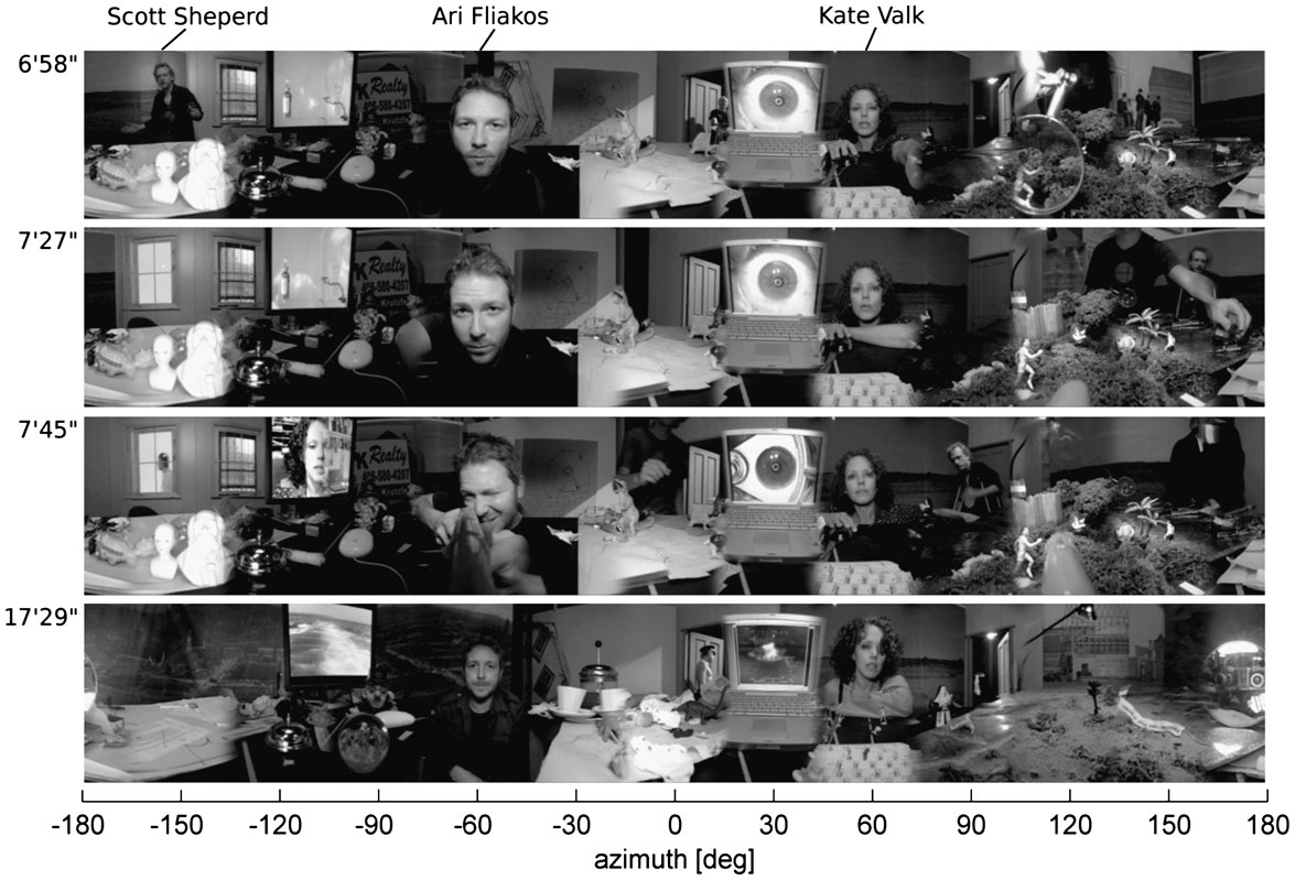
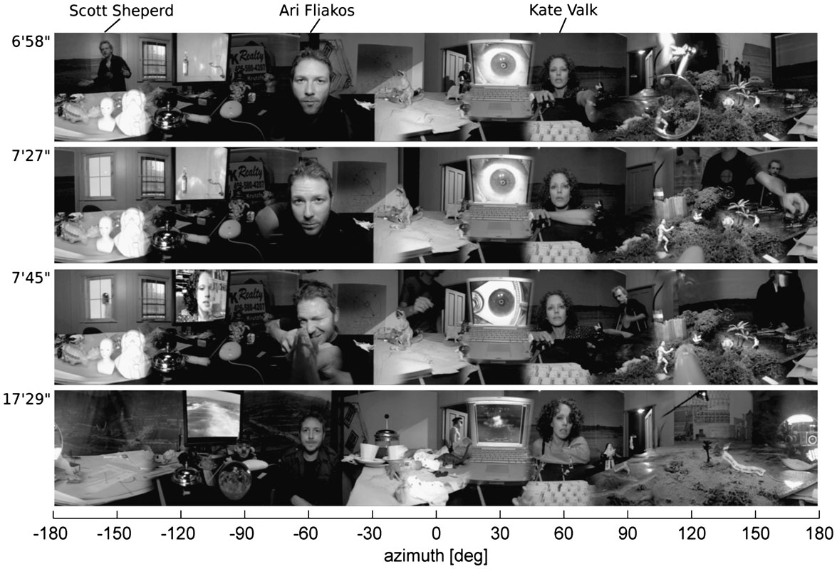
While most of the existing technology (AVIE, Spherecam and the rotating chair) was adequate for the project, the existing screen and audio system did not meet the requirements. As Goebel had already mentioned to Shaw during their time at ZKM, a perforated screen was necessary to be able to place loudspeakers in any location behind the screen and to allow freely steerable movement and localisation of sound, not inhibited by the solid projection screen that had been used so far. Consequently, an acoustically transparent screen with microperforation was chosen for the new system. Further, it was decided to increase the number of audio playback channels to 32 loudspeakers, configured to three rings of 8, 16 and 8 units at different elevations to fully immerse the audience into the play. Foremost, though, was the desire to be able to create virtual acoustic spaces using all existing loudspeakers for early reflections and late reverb. The audio engine of the ZKM Institute for Visual Media’s system, however, simply matched the audio to the interactive video window by reducing the gain of all loudspeakers outside the selected window area. Obviously, this procedure made it impossible to incorporate advanced room-simulation techniques, since the spatially distributed simulated reflections would have been affected by the gain-reducing window settings as well. Furthermore, the underlying ambisonics-type 8- and 12-channel recording setups used by ZKM and UNSW were not applicable for the Wooster Installation either. This technique would have led to excessive cross-talk, and it would not have been possible to filter out those narrative strings that were deselected by the audience through the rotating chair. The fact that the actors were located at close proximity around a centre table, while shooting in their performance garage in SoHo, New York, intensified the problem even more (see figure 1 for stills from the video recording).
Video screen shots from the Wooster Installation. The original video resolution is 8,000×1,200 pixels. Each panel shows a different time frame as indicated in the top-left corners. The stills indicate how the actors move through the setup over time (shown here for actor Scott Sheperd). The bottom still shows how the actors leave the set during the performance. Scott Sheperd, who leaves the set in this scence, is later heard from outside the visual set. At the right side of the bottom panel, the Spherecam was intentionally shown through a hand mirror.
The system that will be described in the following section was driven by the idea that it would be best to record the actors from a very close distance using lavalier microphones. The use of these near-field microphones minimises the cross-talk between all audio channels and maintains the possibility of separating the tracks during the post-production and presentation phases of the project. Unfortunately, by using this technique the spatial positions of the actors were not coded, which was unacceptable given the fine visual resolution and large visual angle of the PanoramaScreen.
To compensate for this shortcoming, a microphone array was installed before the recording and positioned above the centred Spherecam. The positions of the sound sources could be tracked by analysing the captured microphone-array data offline. The technique is described in Section 5. The ViMiC sound spatialisation algorithm was then used to spatialise the near-field recorded sound sources from the measured motion trajectories. While it was sufficient to program the positions manually for most of the static sound sources, other sources changed their positions frequently during the recording. In particular, actor Scott Shepherd’s role was characterised by many position changes during the play (see figure 1).
Most of the background sounds were recorded live as well. For example, the soundtracks of the two laptop computers that are also shown in the stills were part of the play. Later, further Foley sounds were added, and the final project consisted of 54 audio tracks at a sampling rate of 44.1 kHz, 16-bit resolution. Todd Vos and Geoff Abbas from the Wooster Theatre Group edited and post-processed all tracks and added the Foley sounds. All tracks were mixed live in a digital audio workstation and mapped to the aforementioned 32 loudspeakers.
The artistic concept of the Wooster Installation called for a number of rather unusual requirements for the sound system. Unlike in previous AVIE productions, it was not sufficient to simply support the highlighted window acoustically. Instead, an interactive algorithm was designed to emphasise the current primary narrative stream, performed by one of the Wooster group’s actors: Ari Fliakos, Scott Shepherd or Kate Valk. If the window was not pointing to the main narrative stream, the gain of the corresponding channels was only reduced slightly (window gain reduction limiter). Since the video image of the actor was blurred out in these cases, the voice now appeared to come from off-screen. There was an exception to the rule, however, when the window was adjusted to an actor performing a side narrative. In this case, the sound of the the side narrative voice was blended in, while the voice of the main narrator was blended out, although not completely removed (side narrator gain limiter). Most background sounds (Foleys) were emphasised when the window was turned toward them, and their control was typically not affected by the special rules that applied to the narrators.
The CSSD system also needed to support new AVIE video features that were developed by Bernd Lintermann to meet the special requirements of the Wooster Installation: if the window was adjusted to certain scenes, a second window opened at a 180° angle. In one of those scenes, actor Ari Fliakos is seen pointing a gun, and the second window shows the tip of the gun (see figure 1, second panel from bottom). The audio engine followed this exception by opening a second acoustic window, which then emphasised the sound sources in both windows.
4. Sound Spatialisation using Virtual Microphone Control
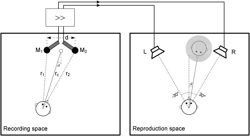
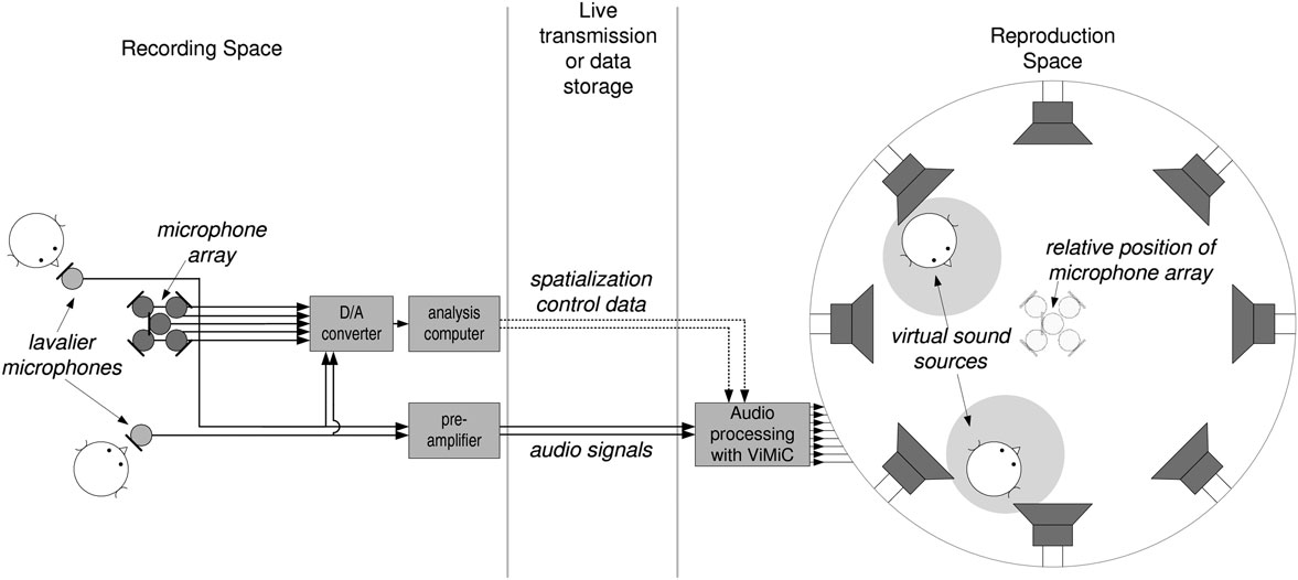
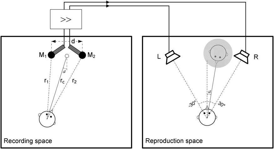
The following paragraphs deal with the fundamental principles of ViMiC. The system basically simulates a multichannel main microphone signal from near-field recordings, descriptors about the room size and wall-absorption coefficients, and the sound-source positioning data. The latter can be provided by a sound-localisation microphone array as described in Section 5. To auralise the signal, each virtual microphone signal is fed to a separate (real) loudspeaker (see figure 2 for the ViMiC recording pathway).
ViMiC virtual recording and reproduction scheme for a simple two-channel microphone array. Shown left is the ViMiC-based virtual recording space and right the physical reproduction setup.
To simulate the influence of walls, floor and ceiling, ViMiC uses the mirror-image technique (Allen and Berkley Reference Allen and Berkley1979) to calculate the position and strength of early room reflections for a rectangular enclosure with adjustable dimension and wall-absorption characteristics. The late reverberant field is considered to be diffuse and simulated through a feedback-delay network (Jot and Chaigne 1991) with 16 modulated delay lines, which are diffused by a Hadamard mixing matrix. By feeding the outputs of the room model into the late reverb unit, a diffuse reverb tail is synthesised, for which the timbral and temporal character can be modified. This late reverb can be efficiently shared across several rendered sound sources.
The core concept of ViMiC involves an array of virtual microphones with simulated directivity patterns. The axial orientation of these patterns can be freely adjusted in 3D space, and the directivity patterns can be varied between the classic patterns that are found in real microphones: omnidirectional, cardioid, hyper-cardioid, sub-cardioid or figure-of-eight characteristics.
The transfer function between the sound source (e.g. a musical instrument which can be treated as a one-dimensional signal in time x(t)) and a virtual microphone is then determined by the distance and the orientation between the microphone’s directivity pattern and the instrument. The distance determines the delay τ between the radiated sound at the sound-source position and the microphone signal y(t):

with the distance r in meters and the speed of sound cS. The latter can be approximated as 344m/s at room temperature (20°C). According to the 1/r law, the sound-pressure level radiated by a sound source will decrease by 6dB with each doubling of the distance r:

with the sound pressure p 0 of the sound source at a reference distance r 0. In addition, it should be considered that the sensitivity of a microphone varies with the angle of incidence according to its directivity pattern. In theory, only omnidirectional microphones are equally sensitive toward all directions, and in practice even this type of microphone is more sensitive toward the front for high frequencies. The circumstance that real microphones generally have rotational directivity patterns simplifies their implementation into the system, since these types of directivity patterns Γ(α) can be written in a simple general form:

The variable α is the incoming angle of the sound source in relation to the microphone axis. Typically, the maximum sensitivity a + b is normalised to one (b = 1−a), and the different available microphones can be classified using different combinations of a and b, with omnidirectional: a = 1 and b = 0; cardioid: a = 0.5 and b = 0.5 and figure-of-eight: a = 0 and b = 1.
The overall gain g between the sound source and the virtual microphone can be determined as follows:

with the distance-dependent gain gd = r 0/r, and the sound source’s rotational radiation pattern Γ(β).
The transfer function between the sound source and the microphone signal can be determined by two parameters only, the gain g and the delay τ, if the microphone and source directivity patterns are considered to be independent of frequency. It is noteworthy that the directivity patterns of most real microphones are not fully independent of frequency, although this is often a design goal. The relationship between the sound radiated from an omnidirectional point source x(t) and the microphone signal y(t) is found to be:


By simulating this physical relationship within the computer-generated environment, the sound sources can be panned in the virtual space according to standard sound recording practices.
Artificial microphone directivity patterns can also be implemented into ViMiC, for example to allow the simulation of classic amplitude-panning techniques. A simple method to create a rotational directivity pattern for this case is to use the cosine function in the following way:

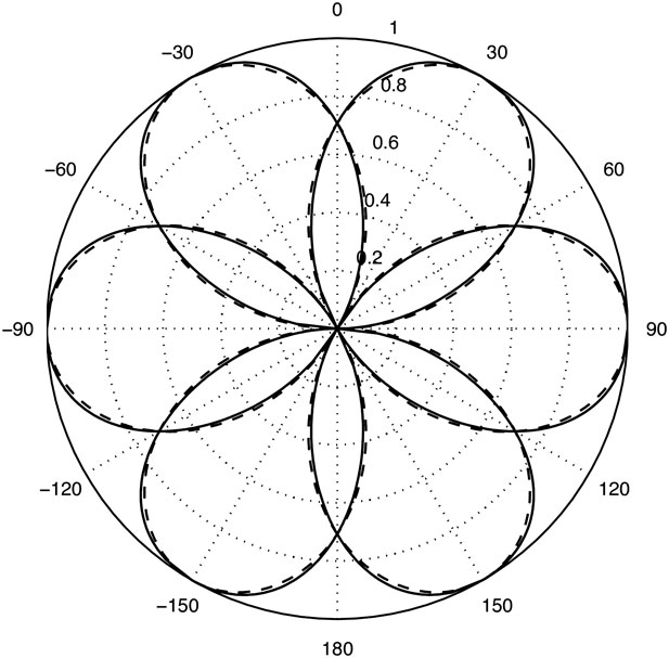
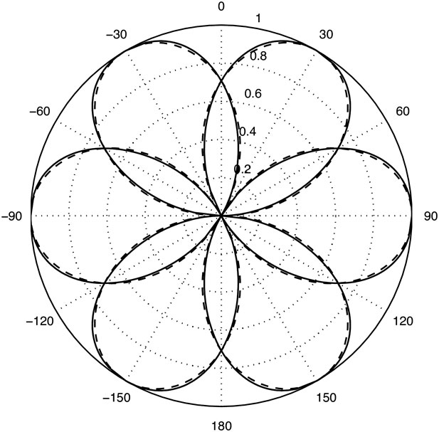
with gi the direction-dependent microphone gain and ϕ 0 the distance to the next speaker. The approach is useful for equi-angular loudspeaker placements (e.g. 22.5°, 45°, or 60°), which are very common in electroacoustic music and are also used in the CSSD system. In this case the sensitivity is 1 if the source is facing the corresponding speaker, and declines to 0 when the source reaches an adjacent loudspeaker. An example for a loudspeaker setup with 60° inter-loudspeaker spacing is shown in figure 3. A configuration for speaker placements with 22.5° and 45° inter-loudspeaker spacing was chosen for the Wooster Installation. The former configuration was used for the 16-loudspeaker centre ring; the latter, for the bottom and top 8-loudspeaker rings.
Polar plots of the sensitivity magnitudes of the directivity patterns that were derived using cosine functions according to Equation 7 (dashed lines) compared to those derived from the tangent panning law with constant power (solid lines).
5. Sound-Source Tracking System
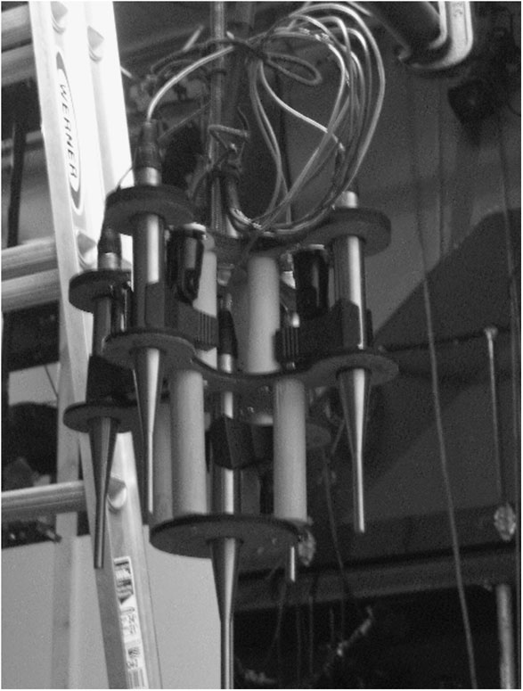
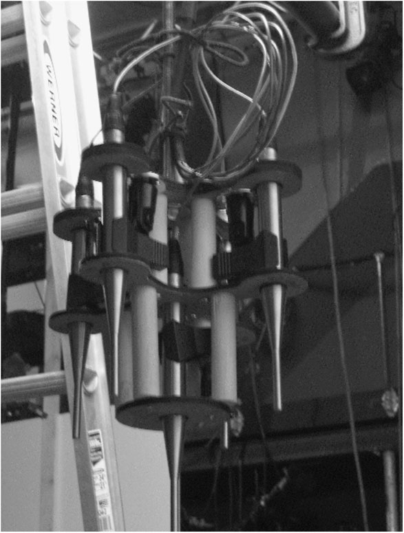
The sound-source tracking system was implemented in the programming environment Matlab and received data from a pyramidal five-microphone array as shown in figure 4. The five omnidirectional microphones are arranged in a square-based pyramid with the following dimensions: base side, 14 cm; triangular side, 14 cm. Traditional microphone-array-based systems work well to localise an isolated sound source by utilising arrival time differences of the sound source between the individual array microphones. In multiple-sound-source scenarios (e.g. a music ensemble), however, determining the sound-source positions from the mixed signal and assigning them to the corresponding source is still a real challenge.
Microphone array.
A solution for this problem is to include the lavalier microphone signals in conjunction with a traditional microphone-array-based localisation system (Braasch and Tranby Reference Braasch and Tranby2007). The lavalier microphone signals are then used to determine the signal-to-noise ratios (SNRs) between a number of sound sources, such as concurrent musicians, while still serving the main purpose of capturing the audio signals. The SNR is calculated frequency-wise from the acoustic energy recorded in a certain time interval:

with:

and p i the sound pressure captured with the i th lavalier microphone, tm the beginning of the measured time interval m, Δt its duration, and N the number of lavalier microphones.
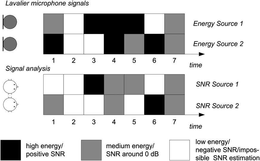
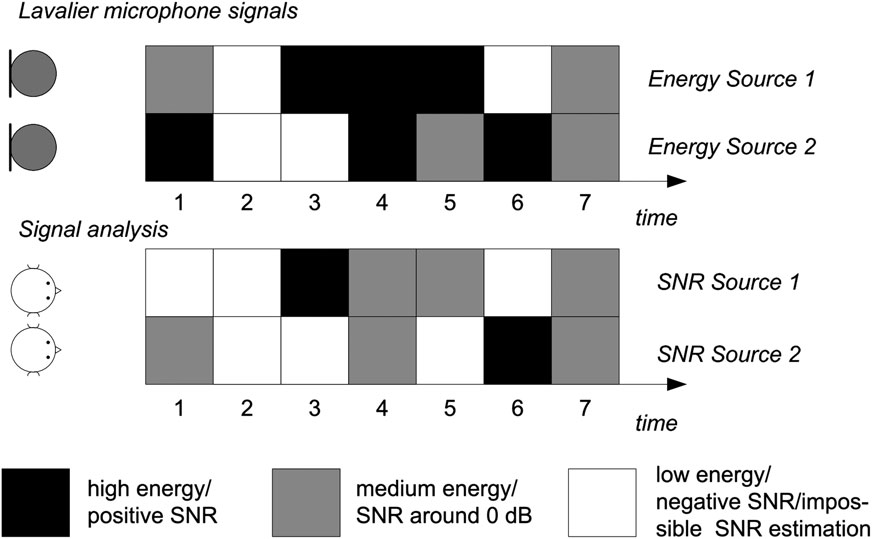
Basically, the SNRs are measured for each time interval between each observed sound source and the remaining sound sources. The data can then be used to select and weight those time slots in which the sound source dominates the scene, assuming that in this case the SNR is high enough for the microphone array to provide stable localisation cues. Figure 5 depicts the core idea. In this example, a good time slot is found for the third time frame for Sound Source 1, which has a large amount of energy in this frame, because the recorded energy for Sound Source 2 is very low. Time Slot 6 depicts an example where a high SNR is found for the second sound source.
Estimation of the signal-to-noise ratios for each sound source.
To improve the quality of the algorithms, all data are analysed frequency-wise. For this purpose the signals are sent through a bandpass filter bank before the SNR is determined. Basically, the SNR is now a function of frequency f, time interval t, and the index of the sound source i: SNR = SNR(f,t,i).
The sound-source position is determined for each time/frequency slot by analysing the time delays between the microphone signals of the microphone array. The position of the sound source is estimated using the cross-correlation technique, which is used to determine the direction of arrival (DOA) from the measured internal delay (peak position of the maximum of the cross-correlation function) via this equation (e.g. see Würfel, Reference Würfel1997):

with the speed of sound c, the sampling frequency fs, the internal delay τ, and the distance between both microphones d.
Since this technique cannot resolve two sound sources within one time-frequency bin, the estimated position is assigned to the sound source with the highest SNR. Alternatively, the information in each band can be weighted with the SNR in this band. To save computational cost, a minimum SNR threshold can be determined, below which the localisation algorithm will not be activated for the corresponding time/frequency slot.
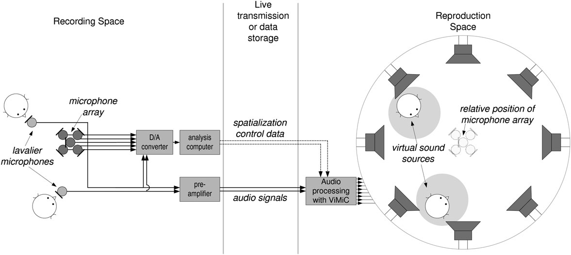
Figure 6 depicts the whole signal chain, which includes the sonification system. At the recording site, the raw sound signals are captured through the lavalier microphones, which also feed the localisation algorithm with information to calculate the instantaneous SNRs. Both the audio data and the control data – which contain information on the estimated sound-source position – are used to resynthesise the spatial sound parameters using ViMiC.
Sketch of the spatial sound recording and reproduction setup.
6. Software Implementation
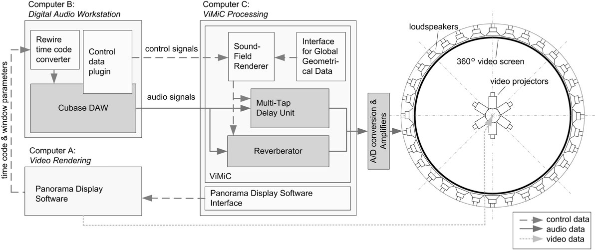
The Wooster Installation was executed from three computers as shown in figure 7. Computer A, which was running a Linux operating system, rendered the video using Lintermann’s Panorama Display Software (PDS). The computer was custom-built from individual parts including three video cards (combination of NVIDIA Quadro FX 4600 and FX 5600 with two DVI outputs each). The rotating chair, built by the ZKM team, was connected to this machine, and PDS used the data to highlight the chosen section by blurring out the remaining window. Computer A transmitted the current time code (minutes, seconds and frames) and the angle of the rotating chair to a second computer, Computer B, using the UDP/ethernet protocol. The position of the second window was also transmitted, along with a parameter which specified whether the window was active or not. In addition, the reference angle was sent, which indicated the position of the 0° angle of the video file relative to the physical screen. This way, the whole movie (audio and video) could be rotated with respect to the door opening in the screen.
System architecture and data routing of the Cinematic Spatial Sound Display (CSSD) and its connection to Lintermann’s PDS system.
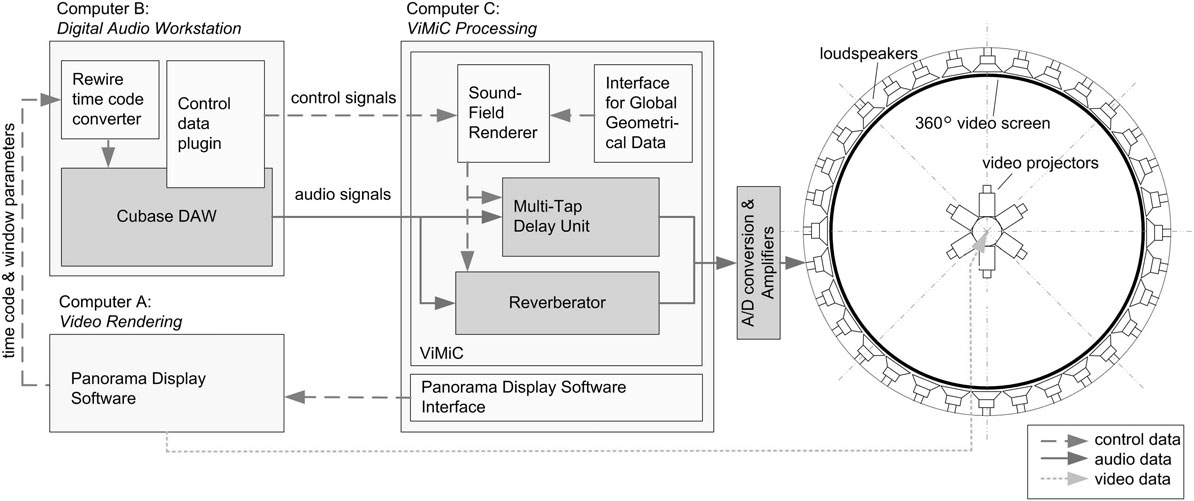
Computer B operated on Windows XP and served as a digital audio workstation (DAW: Steinberg Cubase 4). The project contained 54 tracks that were assigned to 24 output channels. An application was programmed in Max/MSP to receive the control data from Computer A. The time code was then used with the Max/MSP program to synchronise the DAW using the ReWire protocol and to follow cueing commands from the video computer. The remaining data, the chair angle, the reference angle, and information about the second window were passed through to the third machine, Computer C (Apple MacPro), which operated the ViMiC environment. The OpenSound Control protocol was used to transmit these data over a UDP network.
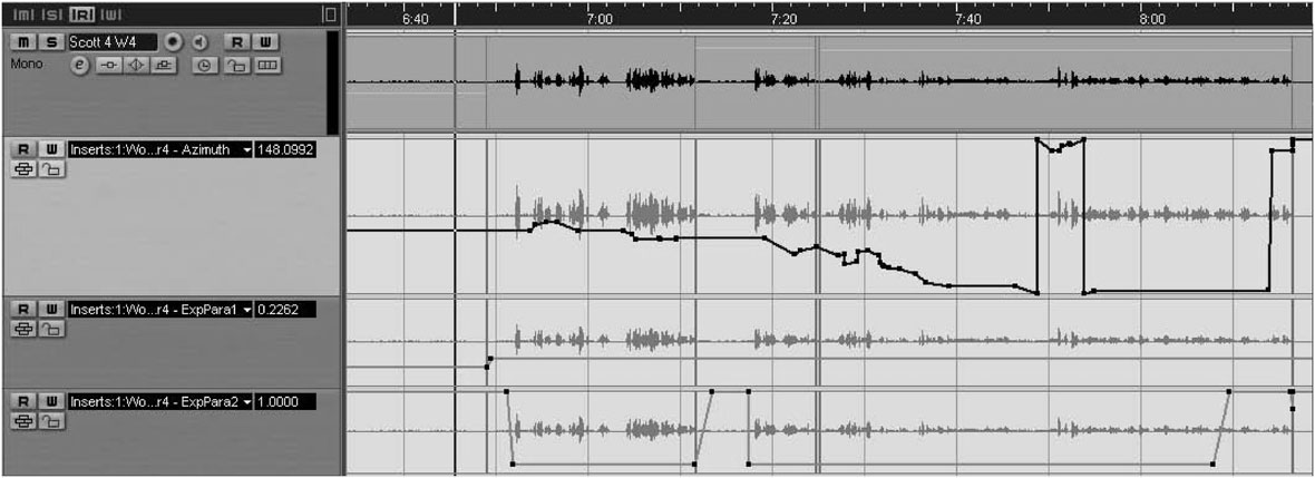
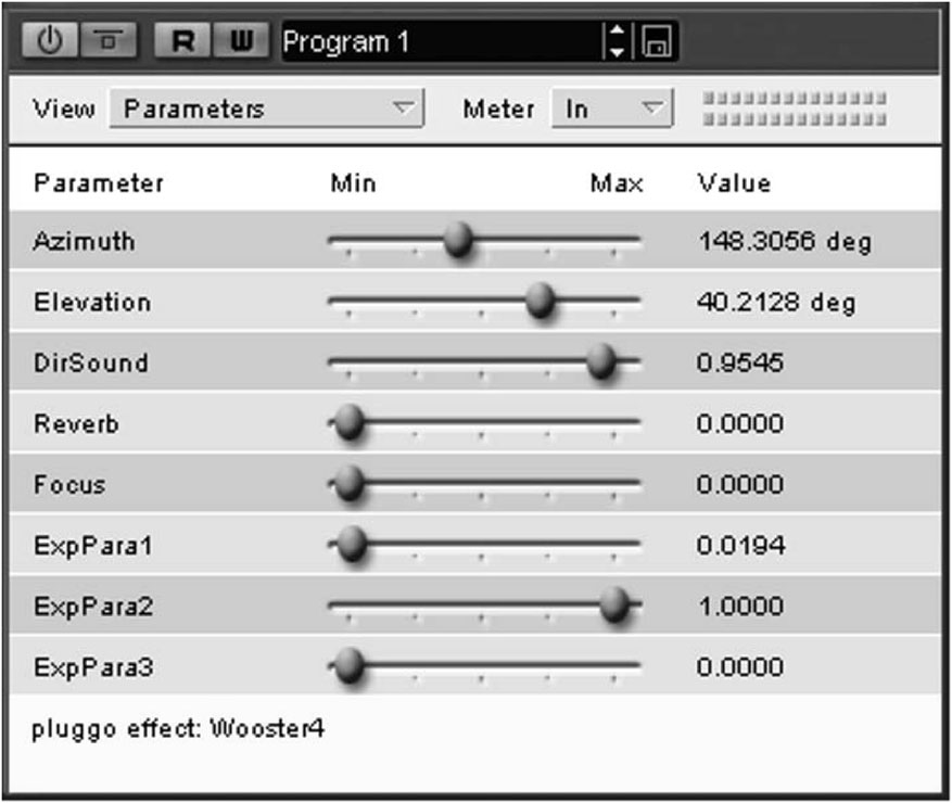
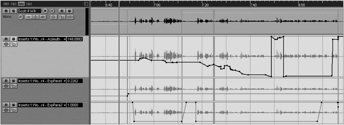
Additional control parameters were stored in the DAW as shown in figure 8. The time-variant parameters contained the azimuth and elevation angles of the sound sources, the reverb level, the window gain reduction limiter level and the first narrator suppressor level. They were stored in the DAW through a custom-designed plug-in (see figure 9). The plug-in is based on the Pluggo Runtime Environment for Max/MSP and runs on VST, RTAS or Audio Units host applications. The patch’s function was to transmit the current settings of the control parameters via Open Sound Control (OSC, Wright Reference Wright2005) to the ViMiC processor. Most of the parameters were adjusted by hand during the mixing and post-production process, which also included time-based level adjustments and equalisation of the individual sound sources.
Screenshot from the DAW for Track 4 containing the voice of actor Scott Shepard. The top curve represents the recorded lavalier-microphone signal. The curve beneath it displays the azimuth angles within a range from 0° to 360° between the bottom and top of panel. The azimuth settings can be compared to the visual positions of the actor in the three upper screen-shot panels of figure 1, with the azimuth positions given at the bottom of this figure as a reference. The next curve (second from bottom) shows the window gain reduction limiter. The parameter range spans the values between 0 (window gain reduction is enabled) and 1 (no gain reduction allowed). The bottom curve shows the values for the side narrator gain limiter. The parameter range spans the values from 0 (other actors are ducked, when the window position matches the azimuth of this track) to 1 (no ducking applies). In the condition shown, the voice of Scott Shepard ducks the side narrators, but the ducking effect is released when Scott’s voice has a break.
VST plug-in for special ViMiC parameters: Azimuth, Elevation, Direct and Reverberation Sound Level. The Focus parameter can be used to set the apparent source width of the sounds. Experimential Parameters 1 and 2 represent the window gain reduction limiter and side narrator gain limiter. At the time of the plug-in development it was not fully clear yet how these experimental parameters were to be configured, and Experimential Parameter 3 was never used for the Wooster Installation.
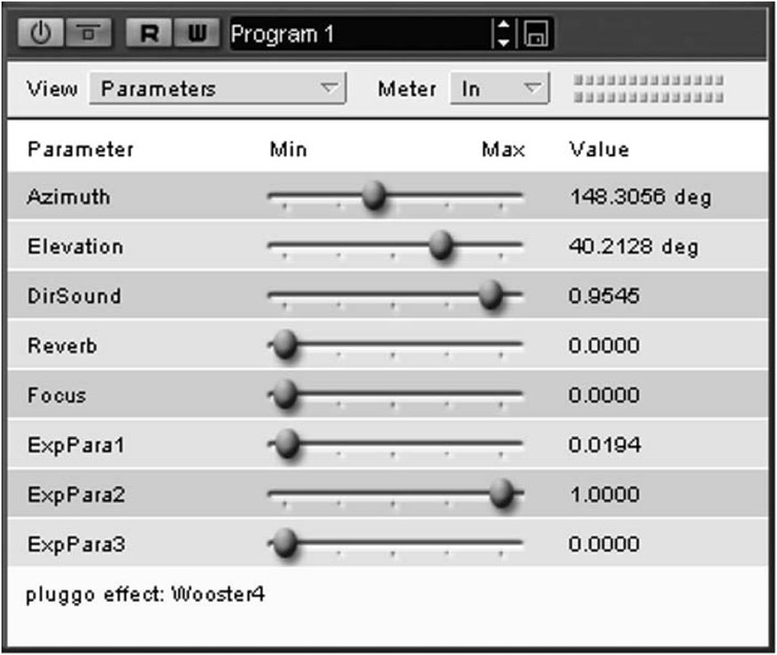
Figure 7 includes the system architecture of the current ViMiC implementation (Computer C). The audio data were transmitted between Computers B and C using 3 ADAT lightpipes to connect the sound cards of both computers (RME 9652 and RME HDSPe MADI). The ViMiC system has three larger signal-processing components: an Image Source Model, a Multitap Delay Unit and a Reverberation Unit. The Image Source Model determines the gains and delays between the sound-source positions and the receiving virtual microphones. The algorithm considers the positions and orientations of both sources and receivers including their directivity characteristics. As noted above, the model uses the mirror-image technique (Allen and Berkley Reference Allen and Berkley1979) to calculate the position and strength of early room reflections for a rectangular enclosure with adjustable dimensions and wall-absorption characteristics. The late reverberant field is considered to be diffuse and simulated through a feedback delay network (Jot and Chaigne Reference Jot and Chaigne1991). The feedback delay network consists of 16 modulated delay lines, which are diffused by a Hadamard mixing matrix. By feeding the outputs of the room model into the late reverb, a diffused reverb tail is synthesised (see figure 7) for which timbral and temporal character may be modified. This late reverb can be efficiently shared across several rendered sound sources.
Using the gain and delay data provided by the Image Source Model, the dry sound is processed using a multitap delay network for spatialisation. Typically a high number of delays have to be computed – for example if first-order reflections are considered ((1 direct source plus 6 first-order reflections) × 6 output channels), then 42 delays have to be processed for each sound source in a six-channel surround system. This number increases to 114 delays if second-order reflections are simulated as well. Several measures have been taken to reduce the computational load. One of them is the automated switch between four-point fractional delays for moving sound sources and non-fractional delays, once the sound source remains stationary. The choice of using a coincidence microphone setup, resembling an amplitude panning technique as shown in figure 3, was also made to keep the computational load under control. This was necessary because of the large number of the input (24) and output (32) channels. In addition, the room simulation algorithm (early reflections and late reverb) was not used for most background sounds. Consequently, only amplitude panning of the direct sound source was required in this case. There was no need to process the sounds through a resource-consuming delay network using this configuration.
The 32 output channels were mapped directly to the 32 loudspeakers (Genelec, 8040) of the video installation using the sound interface and four 8-channel DA converters (Behringer, AD 8000). A master volume was integrated into the ViMiC environment and a USB rotary knob (Griffin, PowerMate) was used to set the master volume. The screen is a Gerriets GAMMALUX, Matte-White Finish Micro-Perforated Projection Screen. The screen is 4.3m high and 36.83m wide. It has a diameter of 12m and the door opening is 85cm wide. The loudspeakers were arranged at the following angles: top ring (mounted at the top of the screen): 0° to 315° in steps of 45°; centre ring (ear level): 11.25° to 348.75° in steps of 22.5°; bottom ring (floor level) 22.5° to 337.5° in steps of 45°.
7. The Cinematic Spatial Sound Display in the context of other projects
The Cinematic Spatial Sound Display is one of EMPAC’s signature technologies and will be further developed in the future. In particular, its modular characteristics ought to be improved, so that it can be more easily used by visiting artists who might be interested in the system. A key advantage of the CSSD system is the scalability to various standard and non-standard loudspeaker configurations. In another project, this feature was used when the voices for the animated characters in the IMAX-format, feature-length movie The Molecularium were spatialised automatically from video-rendering positioning data in Maya. By adjusting ViMiC’s virtual microphones, the project’s sound engineer, Jesse Stiles, was able to compensate for the typical mismatch between the screen width (cinema-type flat screen) and the width spanned by the left and right front loudspeakers of a surround system.
Another application of the system is related to telematic music. Here the system is used to spatialise the the sounds of musical instruments at the remote sites. In this context, it is critical to use loudspeaker-based telematic systems in conjunction with the main-microphone technique. The latter is a standard sound-recording technique, where an array of at least two microphones is positioned at a significant distance from the sound sources to automatically encode the scene’s spatial information across a number of audio channels. This technique, however, typically leads to feedback problems in loudspeaker-based telecommunication scenarios. In music performances this feedback can only be suppressed by capturing the sound sources solely from the near-field and thus losing the spatial information. Unfortunately, echo-cancellation systems do not work well in this case, as they tend to produce audible colorations. Using the system reported here, the spatialisation problem can be solved by estimating the sound-source positions via a microphone array and then reproducing the spatial information using the CSSD system. Since the sound-source tracking can no longer be offline for this application, a microphone array based on coincidence techniques (e.g. ambisonics-based microphone array, first-order, B-format (Pulkki, Merimaa and Lokki Reference Pulkki, Merimaa and Lokki2004; Pulkki and Faller Reference Pulkki and Faller2006)) is beneficial in reducing the computational load. For this class of microphone arrays, only interchannel amplitude differences (and not arrival-time differences) have to be estimated. The expected decrease in localisation accuracy is acceptable for the given application, and the previously described algorithm to analyse multiple sound sources can be applied equally well. The sound-source tracking unit is currently implemented in Matlab, which allows easier prototyping than an implementation in Max/MSP. The Matlab module runs in real-time using the Data Acquisition Toolbox. It receives multichannel audio input and returns the calculated results (positions of individual sound sources) via OSC.
The first commercial album using ViMiC in a telepresence scenario has been released on the Deep Listening record label from Kingston, New York (Tintinnabulate and Soundwire, Braasch, Chafe, Oliveros and Woodstrup Reference Braasch, Chafe, Oliveros and Woodstrup2009). The five-channel Quicktime video is a recording of the Tintinnabulate and Soundwire ensembles performing live at the ICAD 2007 conference in Montreal, Canada (McGill University), RPI, Stanford University and KAIST, Seoul, South Korea. The recording took place before the sound-source tracking system was in place and the positions of the sound sources were adjusted manually.
Another key feature of the ViMiC system that has not yet been discussed is its flexibility in creating spatial imagery. The system is very intuitive for audio engineers who typically think in terms of microphone arrangements rather than in terms of panning laws. Moreover, the proposed approach leads to different sound images from those that result from techniques based on amplitude-panning algorithms. Using conventional panning laws, the placement of virtual sound sources is solely based on interchannel amplitude differences. In contrast, when using ViMiC, the control through virtual microphones also captures interchannel time differences, in a way that is familiar to sound recording engineers.
The possibility of using various combinations of interchannel amplitude and time differences to spatialise sound characterises the system’s flexibility to create new forms of spatial imagery. With regard to the direct sound, current spatialisation systems are typically discussed in terms of sound-source positioning, which can be accurately achieved for many loudspeaker configurations using pure amplitude panning techniques. It therefore comes as no surprise that nearly all spatialisation systems for electroacoustic music are solely based on amplitude panning techniques (e.g. Jot Reference Jot1992; Pulkki Reference Pulkki1997; Ramakrishnan Reference Ramakrishnan2009). The changes in spatial imagery described here go beyond pure changes in spatial position, but are also characterised through the spatial extent of the sound sources and Doppler-shift-induced interchannel frequency variations, among other characteristics. A good example for the latter effect is Karl-Heinz Stockhausen’s Kontakte (1958). Stockhausen created the spatialisation effects using a rotational table – the Rotationstisch. In this device a loudspeaker and the attached waveguide were able to rotate, and the moving loudspeaker was recorded with four microphones, coding both ICTDs and ICLDs. With ViMiC these types of effects can be easily simulated, but with greater flexibility than with an electroacoustic setup.