Introduction
The Siberian traps province is of especial importance among all igneous provinces of the World, as this largest Phanerozoic continental basalt province (Reichow et al., Reference Reichow, Saunders, White, Al'Mukhamedov and Medvedev2005; Sobolev et al., Reference Sobolev, Krivolutskaya and Kuz'min2009) contains the richest Cu–Ni–PGE sulfide deposits. These unique deposits are associated with the mafic–ultramafic chonoliths emplaced during the period of trap volcanism (Urvantsev, Reference Urvantsev1971; Dyuzhikov et al., Reference Dyuzhikov, Distler, Strunin, Mkrtychyan, Sherman, Sluzhenikin and Lurye1988; Naldrett, Reference Naldrett2004).
The study of the Noril'sk intrusions have resulted in many publications (Godlevsky, Reference Godlevsky1959; Zolotukhin, Reference Zolotukhin1964; Smirnov, Reference Smirnov1966; Genkin et al., Reference Genkin, Dudykina and Teleshova1970, Reference Genkin, Distler, Gladyshev, Filimonova, Evstigneeva, Kovalenker, Laputina, Smirnov and Grokhovskaya1981; Dyuzhikov et al., Reference Dyuzhikov, Distler, Strunin, Mkrtychyan, Sherman, Sluzhenikin and Lurye1988; Likhachev, Reference Likhachev1996, Reference Likhachev2006; Turovtsev, Reference Turovtsev2002; Latypov, Reference Latypov2002; Naldrett, Reference Naldrett2004; Ryabov et al., Reference Ryabov, Shevko and Gora2014; Krivolutskaya, Reference Krivolutskaya2014; Sluzhenikin et al., Reference Sluzhenikin, Krivolutskaya, Rad'ko, Malitch, Distler, Fedorenko and Simonov2014; Malitch et al., Reference Malitch, Latypov, Badanina and Sluzhenikin2014, etc.). The sulfide ores and platinum-group minerals (PGM) of the deposits have also been investigated in detail (Distler et al., Reference Distler, Genkin, Filimonova, Khitrov and Laputina1975, Reference Distler, Nikol'skaya, Yeshkova and Rekharsky1976, Reference Distler, Malevsky and Laputina1977, Reference Distler, Sluzhenikin, Laputina and Kulagov1996; Genkin et al., Reference Genkin, Murav'eva and Troneva1966, Reference Genkin, Evstigneeva, Troneva and Vyalsov1969, Reference Genkin, Distler, Gladyshev, Filimonova, Evstigneeva, Kovalenker, Laputina, Smirnov and Grokhovskaya1981; Genkin and Evstigneeva, Reference Genkin and Evstigneeva1986; Begizov et al., Reference Begizov, Meshchankina and Dubakina1974; Razin et al., Reference Razin, Dubakina and Dubinchuk1976; Evstigneeva and Genkin, Reference Evstigneeva and Genkin1983; Barkov et al., Reference Barkov, Martin, Poirier, Tarkian, Pakhomovskii and Men'shikov2000a,Reference Barkov, Martin, Poirier and Yakovlevb; Barnes et al., Reference Barnes, Cox and Zeintec2006; Duran et al., Reference Duran, Barnes, Pleše, Kudra Plešek, Zeintec and Pagé2017, etc.). The stages of PGM formation (Spiridonov, Reference Spiridonov2010) and complex mineral systems (Kovalenker et al., Reference Kovalenker, Laputina, Vyalsov, Genkin and Evstigneeva1972; Evstigneeva and Trubkin, Reference Evstigneeva and Trubkin2006; Sluzhenikin and Mokhov, Reference Sluzhenikin and Mokhov2007, Reference Sluzhenikin and Mokhov2008) have been discussed and substantiated. These studies were related predominantly to the origin of massive and disseminated ores located in the lower parts of the intrusions and beneath them. The ‘low-sulfide’ platinum ores associated with chromite-bearing taxitic gabbro-dolerite of the upper endocontact zones of the Noril'sk 1, Kharaelakh and Talnakh intrusions have also been investigated in detail (Ryabov, Reference Ryabov1984; Distler et al., Reference Distler, Grokhovskaya and Evstigneeva1988; Sluzhenikin, Reference Sluzhenikin2011; Sluzhenikin et al., Reference Sluzhenikin, Distler, Dyuzhikov, Kravtsov, Kunilov, Laputina and Turovtsev1994; Reference Sluzhenikin, Distler, Grigoryeva and Barnes2013; Reference Sluzhenikin, Krivolutskaya, Rad'ko, Malitch, Distler, Fedorenko and Simonov2014; Reference Sluzhenikin, Distler and Grigoryeva2016; Sluzhenikin and Mokhov, Reference Sluzhenikin and Mokhov2015). The term ‘taxitic’ suggests heterogeneous, spotty or schlieren rock texture, which is characterised by the irregular distribution of minerals and aggregates, which may differ from each other by colour, texture, grain size, or mineral composition. The formation of taxitic textures is thought to be due to the change in the physico-chemical conditions of magma emplacement and crystallisation, and because of the presence of re-worked xenoliths trapped by magma at different depths (Emelianenko and Yakovleva, Reference Emelianenko and Yakovleva1985).
Approximately 70 species of minerals of noble metals were been found in various types of ores of the Noril'sk-Talnakh region, including more than 25 species in low-sulfide ores (Sluzhenikin, Reference Sluzhenikin2011). We present here new mineralogical data on chromite segregations in the PGE-low-sulfide horizon of the upper contact zone of the Noril'sk 1 intrusion. Our data reports previously undocumented features of sulfides and PGM occurring in the low-sulfide horizon. Analysis of the sulfide inclusions in various PGM advances our understanding of the evolution of sulfide melts.
Geology and composition of the rocks
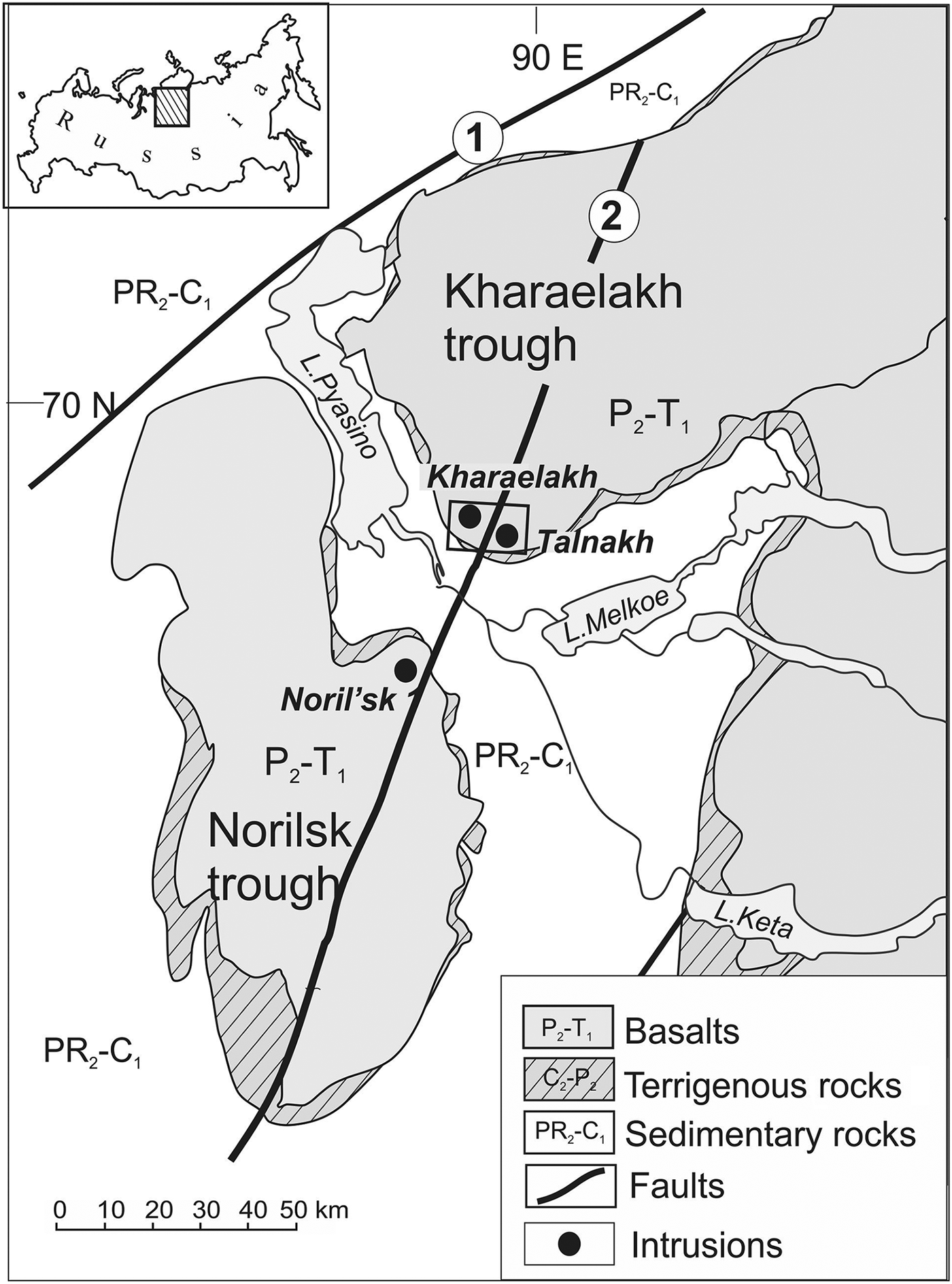
The Noril'sk-Talnakh ore cluster in the Noril'sk region is located in the northwestern part of the Siberian platform at its junction with the Yenisei–Khatanga Trough and the Tunguska syncline. The intrusions intruded sedimentary sequences (coal-bearing rocks, evaporites, and carbonate rocks) of different ages from the Devonian to the Carboniferous and upper Permian (Naldrett, Reference Naldrett2004; Sluzhenikin et al., Reference Sluzhenikin, Krivolutskaya, Rad'ko, Malitch, Distler, Fedorenko and Simonov2014; Krivolutskaya, Reference Krivolutskaya2014). The crystallisation of the ore-bearing intrusions took place during the Permian–Triassic periods (Campbell et al., Reference Campbell, Czamanske, Fedorenko, Hill and Stepanov1992; Kamo et al., Reference Kamo, Czamanske and Krough1996; Malitch et al., Reference Malitch, Badanina, Belousova and Tuganova2012). Only three of many differentiated intrusions host economic PGE–Cu–Ni sulfide deposits: Kharaelakh, Talnakh and Noril'sk 1 (Fig. 1). The first two are situated in the southern part of the Kharaelakh Trough and the third is in the northeastern part of the Noril'sk Trough. The emplacement of the intrusions was controlled by the major 100 km Noril'sk–Kharaelakh fault. The PGE–Cu–Ni ore bodies associated with the intrusions are up to 0.3 km thick and 2 km across. The intrusions are composed of taxitic gabbro-dolerites in the lower part of portion of the cross-section (so-called ‘Lower gabbro series’ according to Distler et al., Reference Distler, Sluzhenikin, Krivolutskaya, Turovtsev, Golovanova, Mokhov, Cabri, Knauf and Oleshkevich1999) (Fig. 2), followed by picritic and olivine-bearing gabbro-dolerites of the Main layered series in the middle part of the section (Naldrett, Reference Naldrett2004; Likhachev, Reference Likhachev2006; Krivolutskaya, Reference Krivolutskaya2014; Sluzhenikin et al., Reference Sluzhenikin, Distler and Grigoryeva2016). Low-sulfide ores are localised in taxitic gabbroic rocks and leucocratic gabbro of the ‘Upper gabbro series’ in the upper endocontact zone (Distler et al., Reference Distler, Sluzhenikin, Krivolutskaya, Turovtsev, Golovanova, Mokhov, Cabri, Knauf and Oleshkevich1999; Sluzhenikin et al., Reference Sluzhenikin, Distler and Grigoryeva2016). The layered series contains disseminated sulfide ores, which increases in amount towards the base of the intrusion. The massive sulfide ores tend to occur along the lower contact of the intrusion between the intrusive and host rocks.
Schematic geological map of the Noril'sk ore region showing the position of the Noril'sk 1 deposit (Sluzhenikin et al., Reference Sluzhenikin, Krivolutskaya, Rad'ko, Malitch, Distler, Fedorenko and Simonov2014). Faults: 1 – Yenisey-Khatanga, 2 – Noril'sk-Kharaelakhsky.

(a) The position of the Upper Gabbro series with a low-sulfide horizon at the base of these series in the section of the Noril'sk 1 intrusion, and its structure at the separate intersections (according to Sluzhenikin et al., Reference Sluzhenikin, Distler and Grigoryeva2016); (b) the outcrop of leucocratic gabbro and taxitic gabbro-dolerites containing chromite schlieren from which samples were selected.
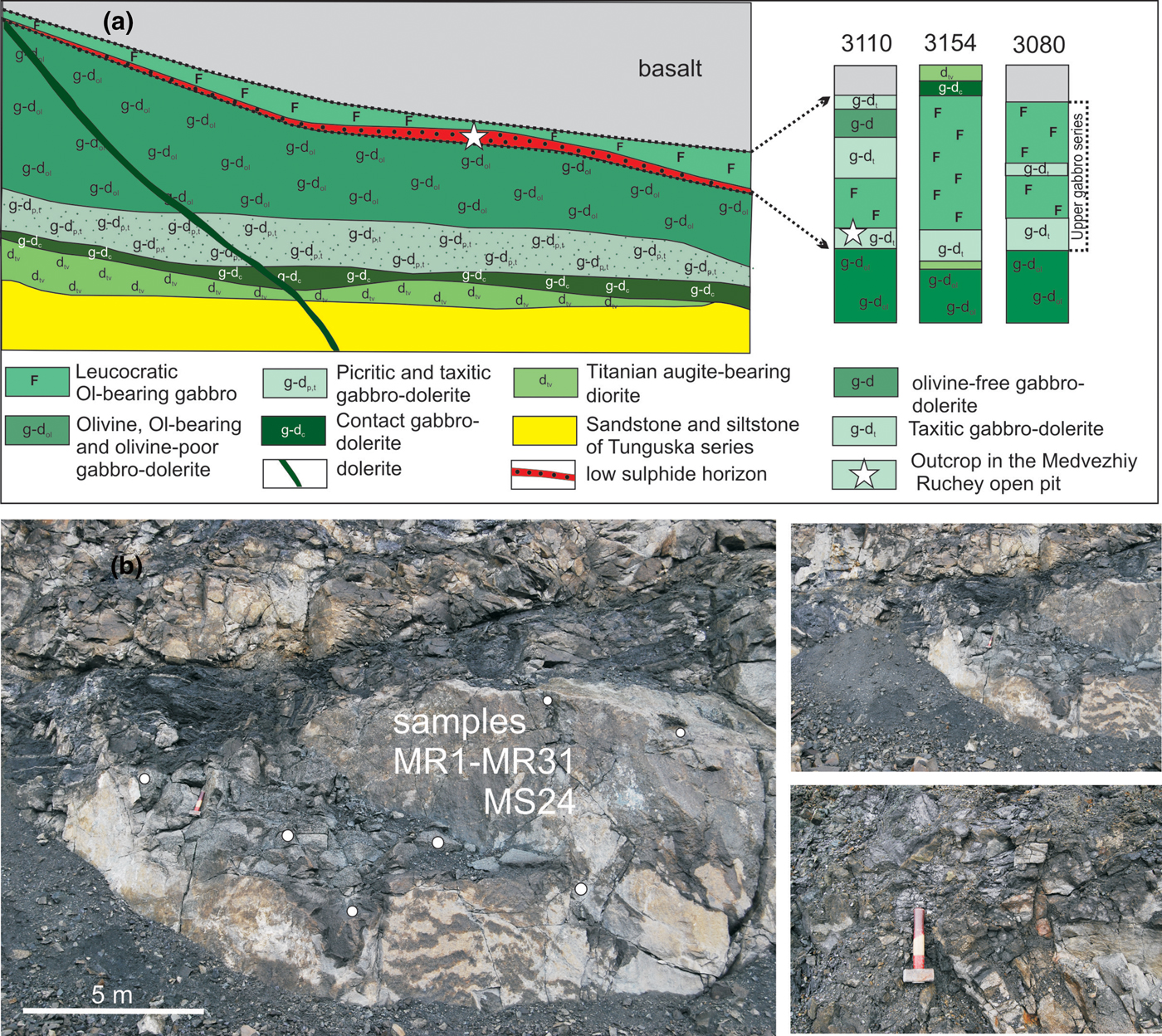
The low-sulfide ore horizon of the Noril'sk 1 intrusion is confined to the lower part of the Upper gabbroic series and composed mainly of gabbro-dolerite, eruptive breccia, hybrid and contaminated rock, leucocratic gabbro, taxitic gabbro-dolerite and gabbrodiorite (Sluzhenikin et al., Reference Sluzhenikin, Distler, Grigoryeva and Barnes2013, Reference Sluzhenikin, Krivolutskaya, Rad'ko, Malitch, Distler, Fedorenko and Simonov2014, Reference Sluzhenikin, Distler and Grigoryeva2016). The chromian spinel-bearing taxitic (or variously textured) gabbro-dolerite is coarse- to fine-grained with a mottled texture. Leucogabbro consists of plagioclase, interstitial augite, accessory phlogopite, titaniferous magnetite, ilmenite, chromian spinel and apatite. Taxitic gabbro-dolerite is composed of plagioclase, augite, minor olivine (<5%), orthopyroxene, titaniferous magnetite, ilmenite, titanite and apatite (Sluzhenikin et al., Reference Sluzhenikin, Distler, Grigoryeva and Barnes2013). The extensive development of H2O-, OH-, Cl- and F-bearing minerals (i.e. apatite, prehnite, phlogopite, biotite, clinochlore, chlorite, saponite, pumpellyite, analcime, zeolites etc.) is typical (Sluzhenikin et al., Reference Sluzhenikin, Distler, Dyuzhikov, Kravtsov, Kunilov, Laputina and Turovtsev1994, Reference Sluzhenikin, Distler, Grigoryeva and Barnes2013, Reference Sluzhenikin, Krivolutskaya, Rad'ko, Malitch, Distler, Fedorenko and Simonov2014, Reference Sluzhenikin, Distler and Grigoryeva2016). The low-sulfide horizon is characterised by discontinuities and is of variable thickness up to 6 m. Likhachev (Reference Likhachev2006) argued that the horizon is composed of different rocks with disseminated PGE–Cu–Ni mineralisation (Likhachev, Reference Likhachev2006). The PGE mineralisation is associated closely with segregations of chromian spinel, and is accompanied by occurrences of Cl-, F-, and OH-bearing minerals (Sluzhenikin et al., Reference Sluzhenikin, Distler and Grigoryeva2016). The low-sulfide horizon differs from the disseminated ores of the layered series by the elevated PGE(g/t)/S(wt.%) ratio, which varies within the range of 5–70, and relatively low Cu and Ni contents (≤ 1 wt.% total), which are correlated positively with PGE (up to 60–70 ppm). Spheroidal textures <1 to 3 cm in diameter, which consist of silicate minerals and sulfides, are characteristic (Sluzhenikin et al., Reference Sluzhenikin, Distler and Grigoryeva2016).
Samples and analytical methods
The chromian-spinel-rich samples from taxitic gabbro-dolerites were sampled in the Medvezhiy Ruchey Mine of the Noril'sk Nickel Company. Sampling was performed from the walls of the northwestern part of the mine at the 300 m level, 69°17′05,0″N, 88°10′13,7″E (Fig. 2). Grains of PGE minerals were separated by grinding six large-volume (~5–8 kg) samples of chromian-spinel-bearing taxitic gabbro-dolerites from the low-sulfide horizon of Noril'sk 1 with subsequent gravitational concentration in water and then in heavy liquid (tribromomethane). Additionally, seven thin polished sections of rocks were used to study the relationship of PGM with the rock-forming and accessory minerals.
All the microanalytical studies of minerals were carried out at the Analytical Centre for multi-elemental and isotope research of the VS Sobolev Institute of Geology and Mineralogy (Siberian Branch of the Russian Academy of Sciences (SB RAS). Polished mounts and thin sections (for in situ measurements) were used to study sulfides and PGE minerals, as well as chromian spinels, ilmenite and silicate minerals. Energy-dispersive spectroscopic (EDS) analyses were obtained using scanning-electron microscopes (SEM) LEO 1413 VP and MIRA 3LMU (TESCAN Ltd.) equipped with INCA Energy 350 and INCA Energy 450 XMax 80 microanalysis systems (Oxford Instruments Ltd.), respectively. The EDS analyses were carried out using an accelerating voltage of 20 kV, a probe current of 1.6 nA, and an accumulation time of 50 s. The following standards were used: diopside (Mg and Ca); Al2O3 (Al); Cr2O3 (Cr); pyrite (S); PtAs2 (As); HgTe (Te); and metallic Ti, V, Fe, Mn, Zn, Co, Ni, Cu, Ru, Rh, Pd, Ag, Sn, Sb, Os, Ir, Pt and Au etc. The detection limit for most elements is 0.2–0.3 wt.% (3σ criterion), but in some cases it can be as high as 0.5–0.8 wt.% in the case of peak overlaps or using the L line for analysing heavy (Z >72) elements. Correction for matrix effects was done using the XPP algorithm. The accuracy and reproducibility of analytical procedures and comparison of wavelength-dispersive spectroscopy with EDS data were evaluated with special tests (Korolyuk et al., Reference Korolyuk, Usova and Nigmatulina2009; Lavrent'yev et al., 2015a,b).
We performed more than 600 EDS analyses of PGM, sulfide, oxide and silicate minerals from the gravity concentrates (samples no. MR1, MR13, MR14, MR20, MR30 and MR31) and 60 analyses from seven polished sections (sample MS24 from borehole, level 324.4 m). A total of 255 grains of PGM (20 to 100 µm in size) were analysed from the heavy-mineral concentrate. Textural relations of PGM grains (≤10 µm) with oxide and silicate minerals were examined in situ in polished sections.
Results
Rock-forming and accessory minerals
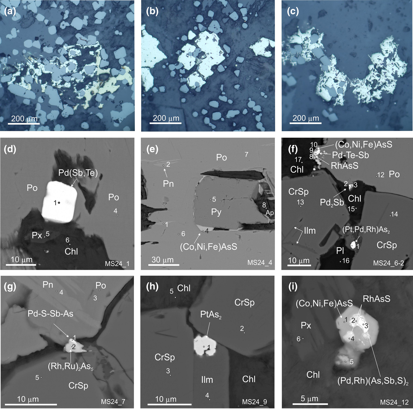
Rock-forming and accessory minerals intergrown with PGM from sulfide segregations are: feldspar; plagioclase; pyroxene; amphibole; chlorite; epidote; chromian spinel; ilmenite; apatite; and rarely chromian magnetite (Fig. 3). Pyroxene is typically replaced by chlorite (Fig. 3a). Olivine was not detected in the samples probably due to its common replacement by chlorite.
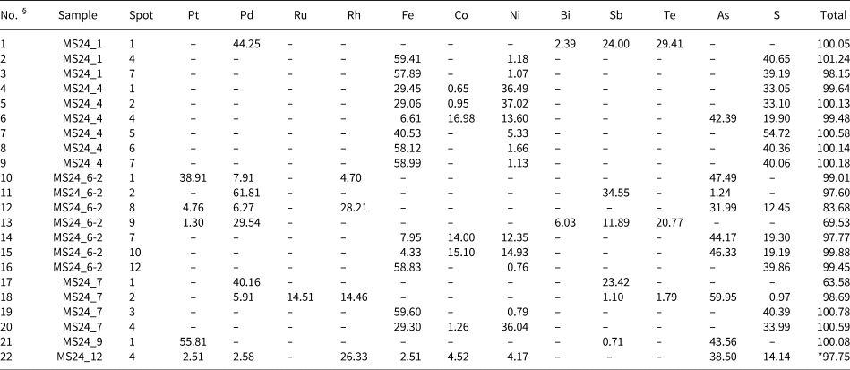
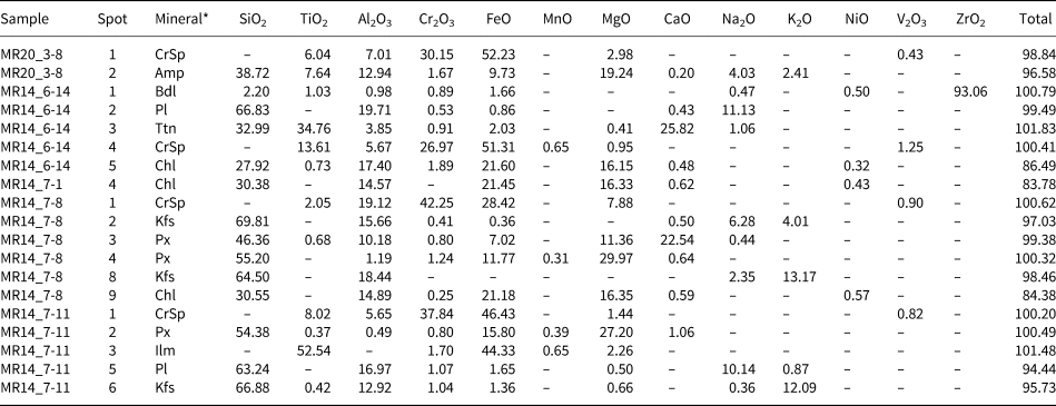
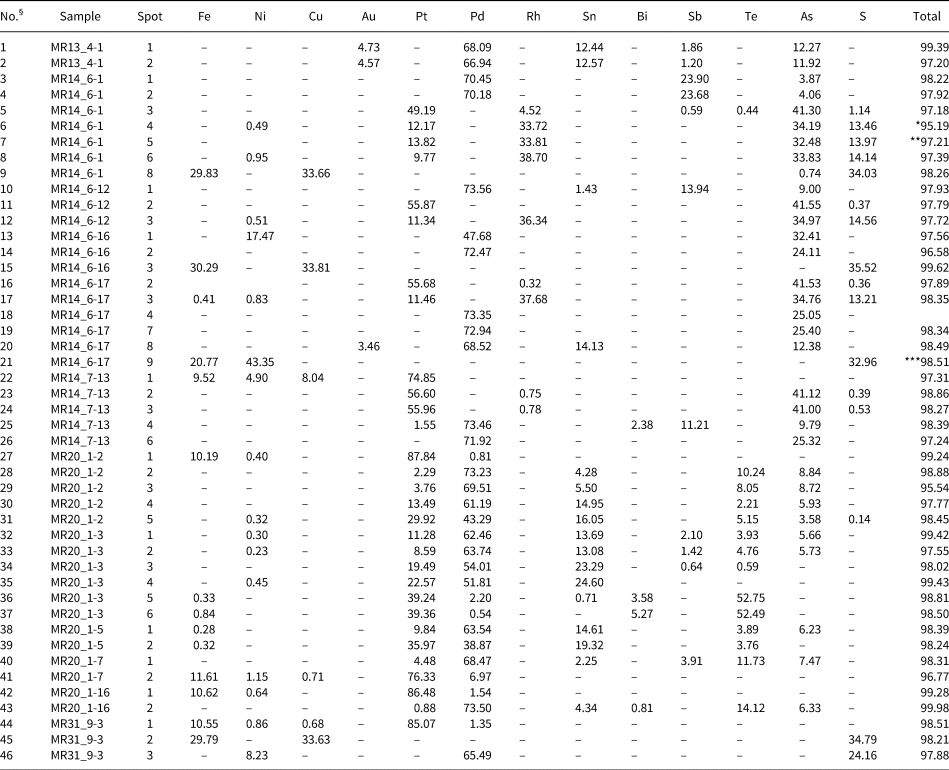
Back-scatter electron (BSE) images illustrating the paragenesis of ore minerals in the low-sulfide horizon. (a–c) Sulfide aggregates and inclusions of chromian spinel (CrSp) in rocks of low-sulfide horizon (in reflected light); (d–j) BSE images: (d) inclusions of kotulskite Pd(Te,Sb) in a pyrrhotite–chlorite (Po-Chl) matrix; (e) pyrite crystal (Py) surrounded by cobaltite (Co,Ni,Fe)AsS and apatite (Ap) in Po; (f) the smallest inclusions of PGM: naldrettite (Pd2Sb), Pd–Rh-bearing sperrylite, hollingworthite (RhAsS) in the marginal part of the Po grain in association of CrSp, chlorite (Chl), and plagioclase (Pl); (g) inclusions of (Rh,Ru)2As5 at the contact of CrSp and Po; (h) inclusions of sperrylite at the contact of CrSp and ilmenite (Ilm); (i) a zonal grain with an unnamed phase (Pd,Rh)(As,Sb,S)2 in the core, surrounded by hollingworthite (RhAsS) and cobaltite–gersdorffite solid solution (Co,Ni,Fe)AsS on contact with pyroxene (Px). The composition of minerals in the spots are given in Table 1.
Composition of minerals (wt.%) from sulfide segregations ilustrated in Fig. 3.

* The total includes 2.50 wt.% Ir
§ Formulas:

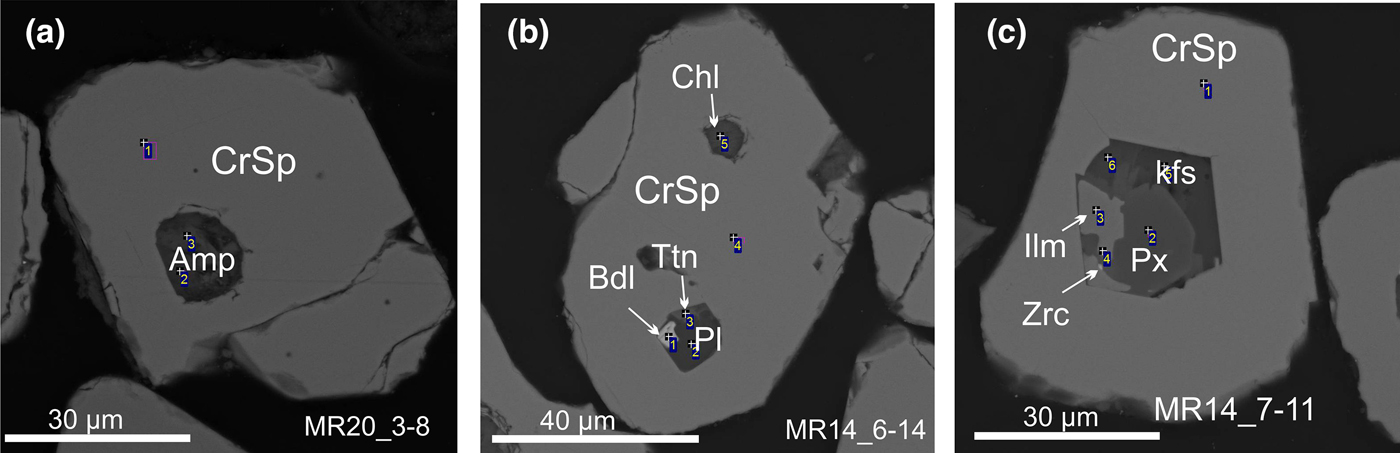
The silicate and oxide droplet-like inclusions in chromian spinel are: amphibole (magnesio-cummingtonite, tschermakitic hornblende, pargasite, magnesio-hastingsite); feldspar; ilmenite; pyroxene; titanite; chlorite; garnet; zircon; and baddeleyite (Fig. 4). Droplet-like inclusions in PGM grains are composed of chlorite, scapolite, ilmenite and feldspar (Fig. 5g,j).
Inclusions of rock-forming minerals in chromian spinel (CrSp) (BSE images). CrSp – Chromian spinel; Amp – amphibole, Bdl – baddeleyite, Ttn – titanite, Pl – plagioclase, Chl – chlorite, Kfs – K + feldspar, Px – pyroxene, Ilm – ilmenite, Zrc – zircon. The composition of minerals in the spots are given in Table 1.

The drop-shaped inclusions of sulfides (a–f, k, l), chromian spinel (h,i) and silicate (j) in PGM (BSE images). Isf – isoferroplatinum, Po – pyrrhotite, Pn – pentlandite, Ccp – chalcopyrite, Sp – sperrylite, Mrt – mertieite-I.

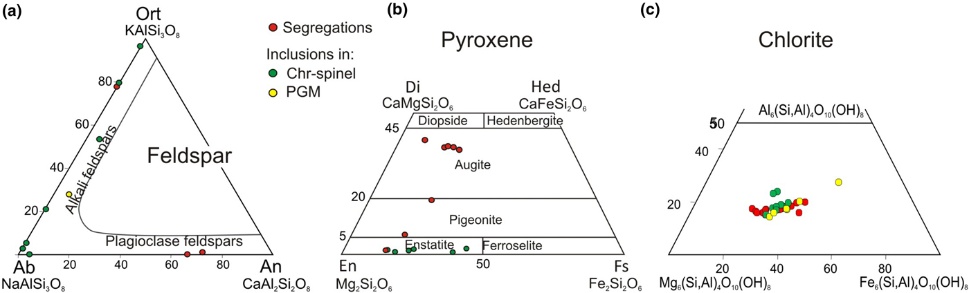
The composition of feldspar varies widely: albite–anorthite solid solutions (An68–72Ab28–32) are found in sulfide segregations whereas albite–orthoclase from Ab97Or3 to Or98Ab2 are found as inclusions hosted by chromian spinel and PGM (Fig. 6a). The analysed pyroxene grains are Wo8–22En57–74Fs17–20 and Wo43–46En38–47Fs6–13 in the sulfide segregations whereas Wo1–8En74–83Fs14–17 occur in the droplet-like inclusions (Fig. 6b). Chlorite, predominantly clinochlore (Mg,Fe2+)5Al(Si,Al)4O10 and probably ‘orthochamosite’ (Fe+2,Mg, Fe+3)5Al2Si3O10(O, OH)8 is a ubiquitous mineral (Fig. 6c).
The compositions of feldspar (a), pyroxene (b) and chlorite (c).

Chromian spinel
Chromian spinel forms abundant impregnations in sulfides and silicates (Fig. 3a-c) or clusters and can be intergrown with plagioclase, chlorite, pyroxene, sulfide and PGM (Fig. 3d–i). The euhedral grains of chromian spinel are typically surrounded by chlorite (Fig. 3f,h). The chromian spinel segregations tend to be associated with Cl-, F- and OH-bearing minerals (Genkin et al., Reference Genkin, Distler and Laputina1979; Ryabov, Reference Ryabov1984; Reference Ryabov1989; Sluzhenikin et al., Reference Sluzhenikin, Distler, Dyuzhikov, Kravtsov, Kunilov, Laputina and Turovtsev1994). Lamellae of exsolved ilmenite commonly appear in the chromian spinel matrix (Fig. 3f). In addition, tabular crystals of ilmenite occur in intergrowths with chromian spinel (Fig. 3h). Inclusions of chromian spinel were also found within sperrylite crystals (Fig. 5h,i).
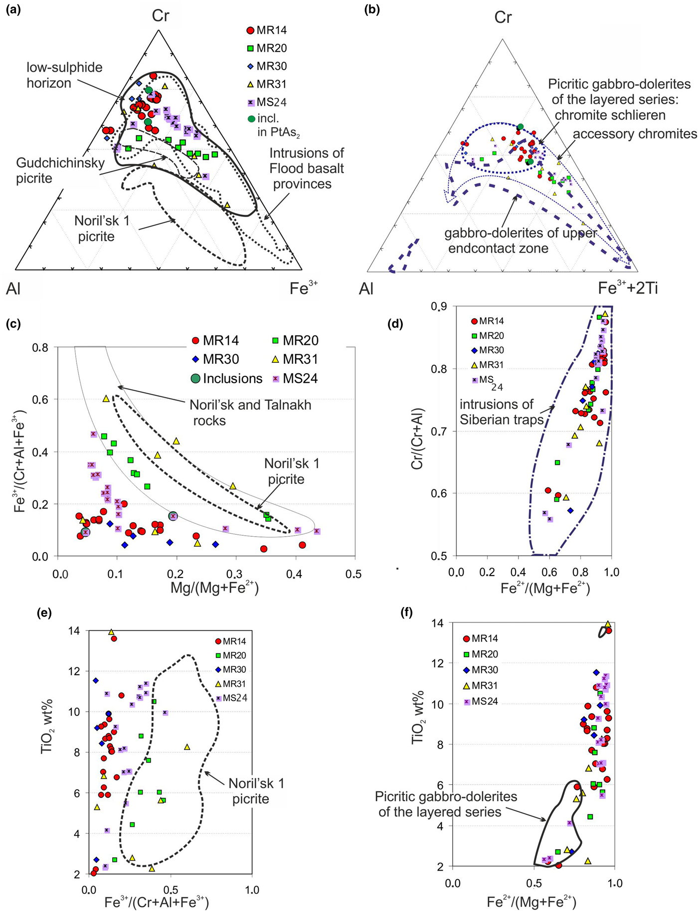
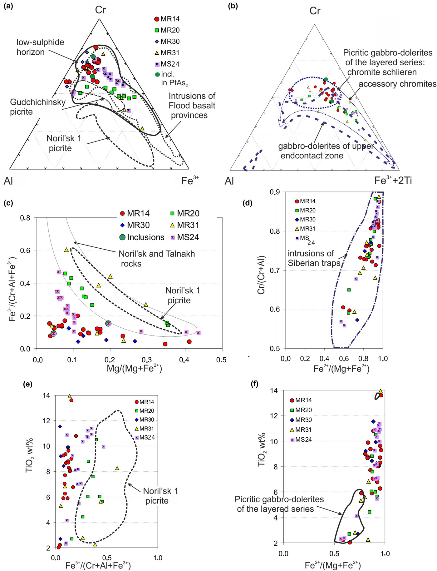
The compositions of the chromian spinels vary widely (Supplementary Table S1) forming two trends: one with well pronounced Cr–Fe3+ (MS24 and MR20 samples) and one weak Cr–Al trend (MR14 and MR30 samples) (Fig. 7a). The compositions of chromian spinel included in sperrylite plot in the same field as the compositions of disseminated chromian spinels (Fig. 7a). The compositions of chromian spinel from samples MR20 and MR31 are similar to those of accessory chromite from the picritic gabbro-dolerite of the layered series on the diagram Al–Cr–Fe3++2Ti (Ryabov et al., Reference Ryabov, Shevko and Gora2001) (Fig. 7b) and plot in the field ‘Noril'sk and Talnakh rocks’ in the Fe3+/(Cr + Al + Fe3+) vs. Mg/(Mg + Fe2+) diagram according to Barnes and Kunilov (Reference Barnes and Kunilov2000) (Fig. 7c). The Ti content in the chromian spinel varies from 2.05–13.94 wt.% TiO2 whereas the Ni content is below the detection limit (Table 2, S1). A low value of the Fe3+/(Cr + Al + Fe3+) ratio (Fig. 7e) and the positive correlations between TiO2 and Fe2+/(Mg + Fe2+), in addition to that between Cr/(Cr + Al) and Fe2+/(Mg + Fe2+) are characteristic of these chromian spinels (Fig. 7f,d).
The compositions of chromian spinel: (a, b) trivalent ion plots of chromian spinels, (c) Fe3+/(Cr + Al + Fe3+) vs. Mg/(Mg + Fe2+); (d) Cr/(Cr + Al) vs. Fe2+/(Mg + Fe2+); (e, f) TiO2 vs. Fe3+/(Cr + Al + Fe3+) and Fe2+/(Mg + Fe2+). The contoured field for subvolcanic intrusions of the Flood basalt provinces is according to Barnes and Roeder (Reference Barnes and Roeder2001), Noril'sk 1 and Gudchichinsky picrites, Noril'sk and Talnakh rocks according to Barnes and Kunilov (Reference Barnes and Kunilov2000), gabbro-dolerites of upper endocontact zone, picritic gabbro-dolerites of the layered series (chromite schlieren and accessory chromites) according to Ryabov et al. (Reference Ryabov, Shevko and Gora2001). Original data are given in Supplementary Table S1.
Composition of silicates and oxides from droplets in chromian spinel (Fig. 4) and sperrylite (Fig. 5).

* Bdl – baddeleyite, Pl – plagioclase, Ttn – titanite, CrSp – chromian spinel, Chl – chlorite (clinochlore), Kfs – K feldspar, Px – pyroxene (enstatite), Ilm – ilmenite, Amp – amphibole (magnesio-cummingtonite); Zrc – zircon.
‘–’ = below the detection limit.
Sulfides and sulfoarsenides of base metals
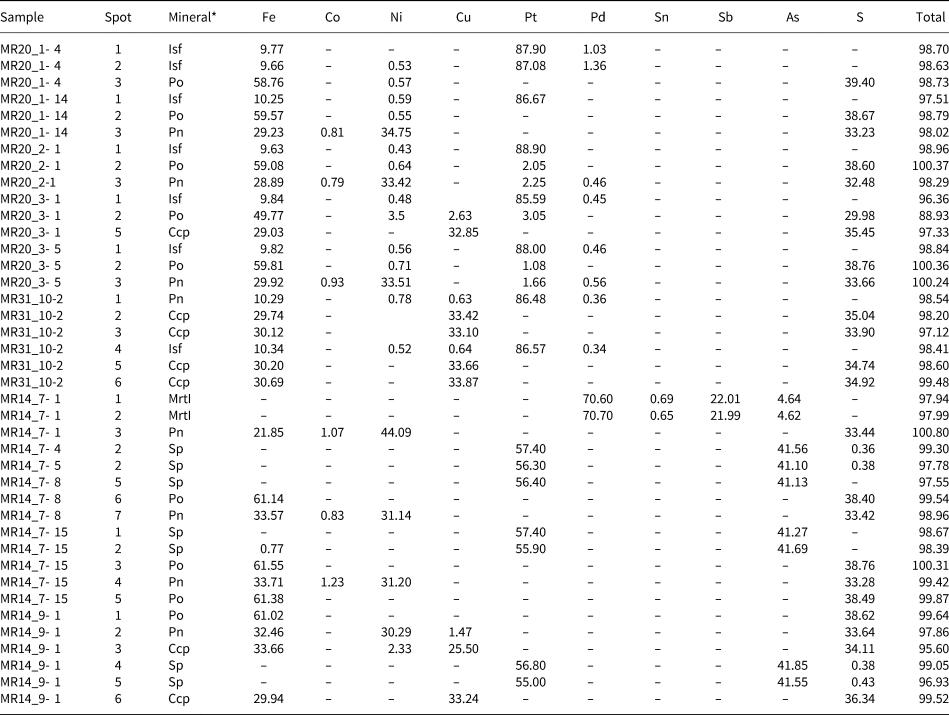
Sulfides of base metals occur in two textural settings: (1) as irregular segregations locally with PGM inclusions and commonly in intergrowths with chromian spinel and ilmenite included in the silicate matrix (Fig. 3); (2) as droplet-shaped inclusions in sperrylite (10 occurrences), Pt–Fe alloys (19 occurrences) and mertieite-I (one occurrence) (Fig. 5). The sulfide inclusions in PGM are composed of one-phase (Po, Pn or Ccp), two-phase (Po + Pn) and three-phase (Po + Pn + Ccp) assemblages (Fig. 5). Chalcopyrite is not present in 10 inclusions in sperrylite grains whereas pyrrhotite–pentlandite intergrowths is common. Chalcopyrite composes the whole inclusion in five examples or is part of a complex droplet-like inclusion in Pt–Fe alloys (19 examples) with pyrrhotite and or pentlandite being dominant minerals in 12 and 11 occurrences, respectively.
The sulfide mineralisation of the low-sulfide horizons of the Noril'sk-Talnakh deposits includes three associations: pentlandite–chalcopyrite–pyrrhotite, pentlandite–pyrrhotite and millerite–chalcopyrite–pyrite (Sluzhenikin et al., Reference Sluzhenikin, Distler and Grigoryeva2016). The sulfide segregations in our samples contain all these minerals, but pyrrhotite is the most common, pentlandite is less abundant, and chalcopyrite and millerite are minor.
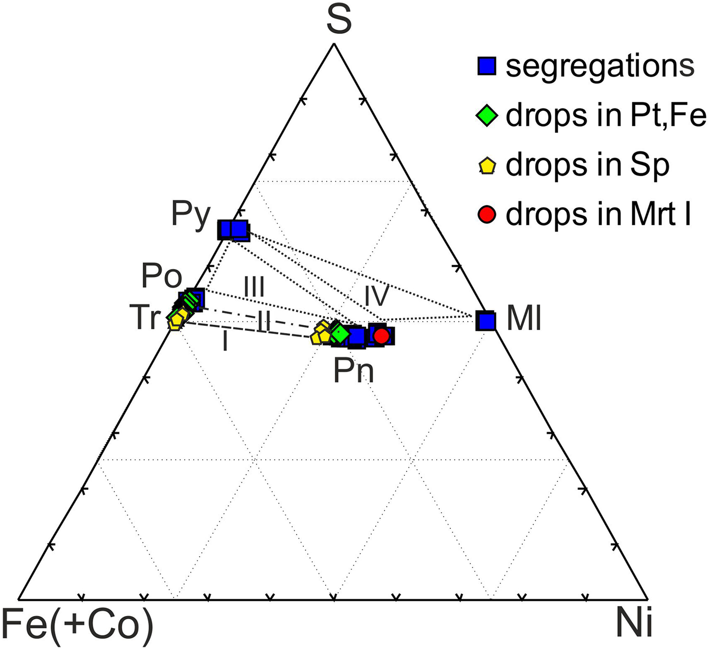
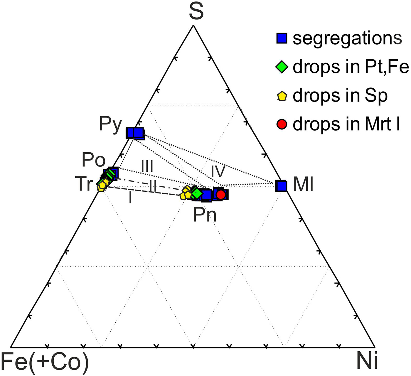
The composition of Fe monosulfides varies from troilite Fe0.99S1.01 (inclusions in sperrylite) to intermediate pyrrhotite (Fe0.95Ni0.01)0.96S1.04 (inclusions in Pt–Fe alloys) and to monoclinic pyrrhotite Me0.91S1.09 in the sulfide segregations (Tables 2, 3, S2, Figs 8, 9). It typically contains Ni (up to 1.66 wt.%).
The compositions of sulfides from sulfide segregations and from inclusions in PGM. Py – pyrite, Po – pyrrhotite, Tr – troilite, Pn – pentlandite, Ml – millerite. I – paragenesis in a droplets in sperrylite (MR14), II – paragenesis in a droplets in Pt–Fe alloys (MR20), III – paragenesis in the sulfide segregations (MR30, MS24), IV – paragenesis in the sulfide segregations (MR31).
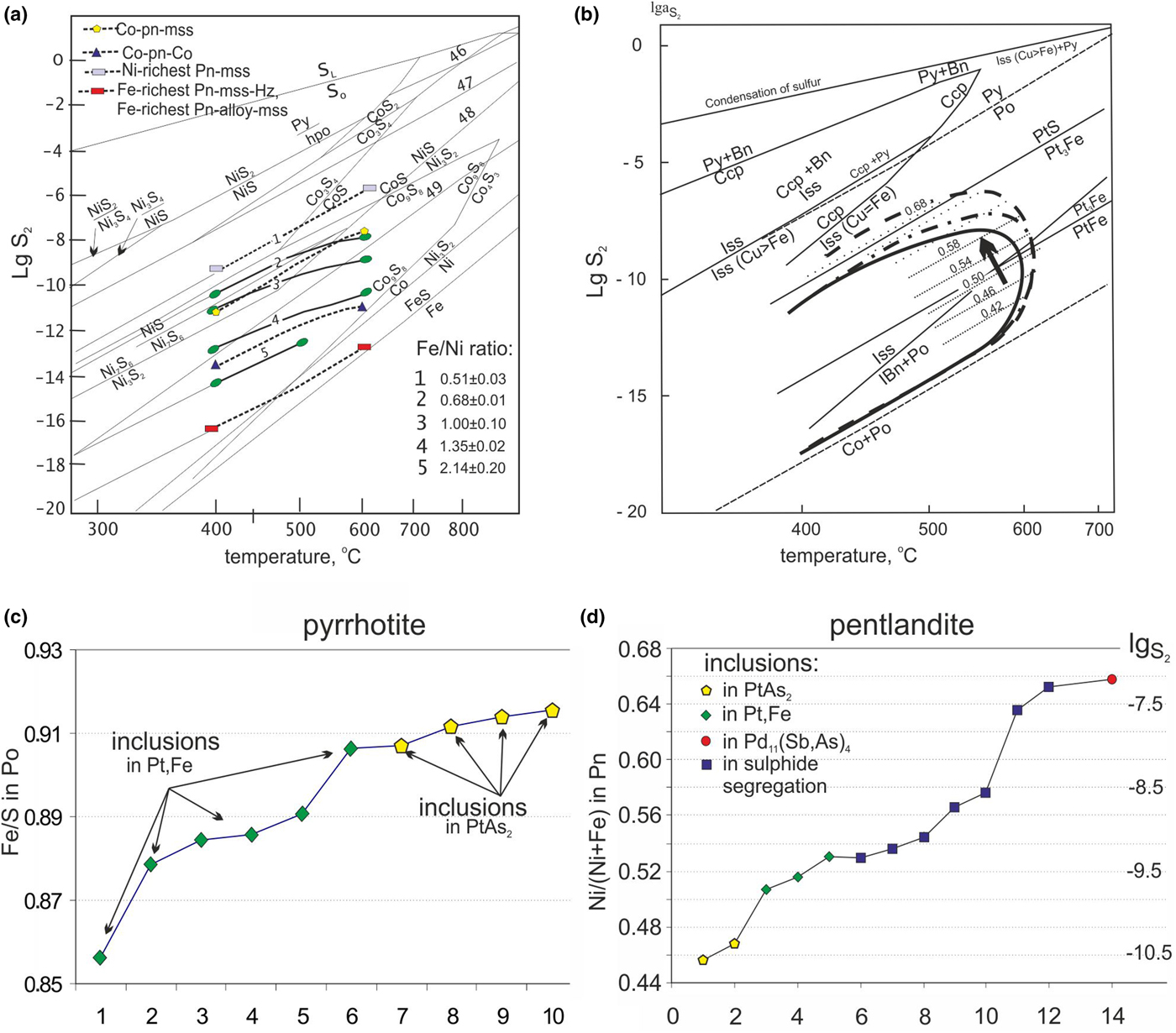
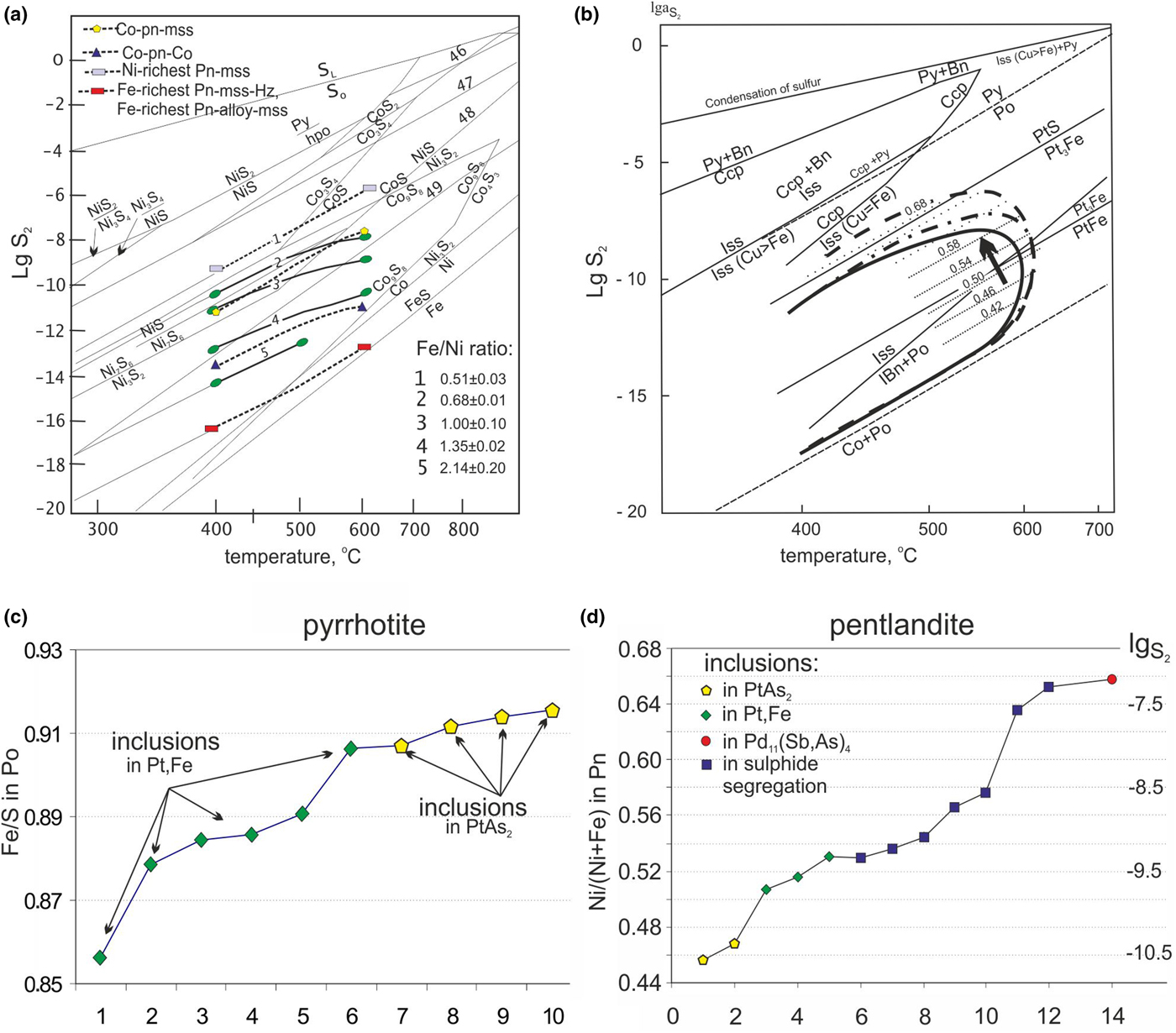
Fugacity of S2. (a) Temperature diagram showing the composition of the pentlandite with Fe:Ni atomic ratio (line 1–5); thermodynamic data are from Barton and Skinner (Reference Barton, Skinner and Barnes1967). (b) Physical and chemical conditions of the pentlandite and Pt minerals with respect to the phase equilibria for the Cu–Fe–S and Ni–Fe–S systems (from Kolonin et al., Reference Kolonin, Orsoev, Sinyakova and Kislov2000). Continuous elliptical curve line – the boundary of the field of stability of pentlandite from Vaughan and Craig (Reference Vaughan and Craig1978), the dotted curve from Peregoedova (Reference Peregoedova1999). The dotted lines within the pentlandite field indicate the change of Ni/(Ni + Fe) ratios with decreasing temperature and increasing sulfur fugacity. The vector indicates the evolution of pentlandite compositions. (c, d) The ratios of Fe/S in pyrrhotite (c) and Ni/(Ni + Fe) in pentlandite (d) showing the change in sulfur fugacity (logS2) in the sulfide associations based on diagram (b).
Compositions of PGM matrix and sulfide droplets illustrated in Fig. 5.

* Isf – isoferroplatinum, Po – pyrrhotite, Pn – pentlandite, Ccp – chalcopyrite, Sp – sperrylite, MrtI – mertieite-I
‘–’ = below the detection limit.
Commonly, lamellae of pentlandite occur in a pyrrhotite matrix (Fig. 3b,d), although granular pentlandite grains are also present. The (Fe + Co)/Ni ratios of pentlandite vary from 0.54–1.19. Iron-rich pentlandite with a Ni/(Fe + Ni) ratio of 0.46–0.47 is found only as sulfide inclusions in sperrylite. The concentration of Ni exceeds Fe in other analysed grains. The Ni content increases from pentlandite with a Ni/(Ni + Fe) ratio of 0.51–0.53 hosted in Pt–Fe alloys to pentlandite in the sulfide segregations. Lamellar pentlandite has a Ni/(Fe + Ni) ratio of 0.53–0.54, granular pentlandite - 0.55–0.56, whereas this ratio reaches 0.64–0.65 in pentlandite intergrown with PGM. The pentlandite inclusion in mertieite-I is the most enriched in Ni (Ni/(Fe + Ni) = 0.66) (Fig. 9). Cobalt is common as an admixture in pentlandite (0.73–1.86 wt.%) (Tables 2, 3, S2).
Euhedral grains of pyrite in sulfide segregations associated with chlorite, cobaltite and chromian spinels (Fig 3d-f,i) are present in most samples, and with millerite in the MR31 sample only (Fig. 8). Pyrite contains up to 5.33 wt.% Ni (Tables 2, S2). Chalcopyrite occurs in subordinate amounts and is intergrown with pyrrhotite. Millerite is found in only one sample (MR31), where it is closely intergrown with chalcopyrite. It contains minor Fe and Co (Table S2).
PGE-minerals
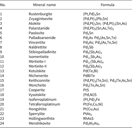
Grains of PGM are distributed heterogeneously in the low-sulfide horizon of the Noril'sk 1 intrusion. Each of the seven samples examined of chromian spinel-bearing ores differ in abundance of PGM species and is characterised by a specific PGM assemblage. In the MR13 and MS24 samples only a few PGM grains were found, whereas there were tens of grains in others (MR14, MR31). Twenty four PGM species were recognised (Table 4). The most common are Pt–Fe alloys (Fig. 10) (isoferroplatinum and ferrous platinum), found mostly in sample MR20. Sperrylite is common mainly in sample MR14. Cooperite, moncheite, rustenburgite, tetraferroplatinum and hongshiite are much less common. Hollingworthite is the only Rh-dominant mineral and is associated with sulfarsenides of Co, Ni and Fe (Fig. 3e,f,i). Species rich in Pd were also recognised (Table 4). Unnamed phases have been identified, which are the As and Sn analogues of mertieite-I and mertieite-II and an Sb analogue of vincentite with various proportions of Pd, Pt, Au and As, Sb, Te and Sn (Table 5). Au–Ag(Pd) alloys were also found in an association with PGM.
The ratio of PGM in the samples of the low-sulfide horizon of the Noril'sk 1. Unn – the unnamed phases (Table 5); others – the rest of the PGM.

PGE minerals in the samples investigated.

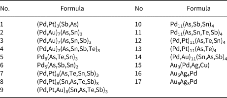
Unnamed PGE phases and variations in their compositions.

The PGM in situ were found as small grains or crystals (5–10 µm) within the intergranular space between sulfides, chromian spinel and ilmenite (Fig. 3a,d,e) in the chlorite matrix and less commonly as inclusions at the edge of the sulfide grains (Fig. 3f). PGM grains of the larger sizes (30–100 µm) were found mostly in the fractions of the crushed samples (Figs 11, 12).
Paragenesis of PGM (BSE images). (a) Grains of unnamed phase (Pd,Au)7(As,Sn,Sb)3 intergrown with sperrylite chlorite (chl); (b) inclusions of sperrylite and gold (Au,A) in mertieite-II; (c) intergrowths of isomertieite Pd8Sb2As2, sperrylite and hollingworthite; (d) menshikovite Pd3Ni2As3 in intergrowths with palladoarsenide Pd2As; (e) grains of sperrylite PtAs2 intergrown with hollingworthite RhAsS, palladoarsenide Pd2As, unnamed phase (Pd,Au)7(As,Sn)3, palladoarsenide, pentlandite and chlorite; (f) multiphase grain composed of sperrylite, palladoarsenide, tetraferroplatinum Pt(Fe,Cu,Ni), hongshiite Pt(Cu,Pd) and vincentite Pd3(As,Sb) including Au,Ag; (g) grain of vincentite Pd3(As,Te,Sn) with inclusions of atokite (Pd,Pt)3(Sn,As,Te), palarstanide (Pd,Pt)5(Sn,As,Te)2 and Pt–Fe alloy; (h) intergrowths of Sn analogue of mertieite-I, atokite and moncheite PtTe2; (i) intergrowths of Sn analogue of mertieite-I and atokite; (j) intergrowths of the As analogue of mertieite-I and (Pt,Pd)3Fe; (k) intergrowths of the Te analogue of vincentite and Pt–Fe alloy; (l) intergrowths of Pt,Fe with chalcopyrite, sperrylite and vysotskite (Pd,Ni)S.

Paragenesis of PGM (BSE images). (a) grains of isoferroplatinum Pt3Fe with inclusions of moncheite (Pt,Pd)Te2, vincentite Pd3(As,Te,Sn) and unnamed (Pd,Pt)3Sb; (b) grains of Pt–Fe alloys with atokite (Pd,Pt)3Sn; (c) intergrowths of stibiopalladinite Pd5Sb2, Au-Ag and sperrylite PtAs2; (d) grains of vincentite overgrown by Pt–Fe alloy and unnamed phase; (e) Au–Pd alloy (Au3Pd) in intergrowths with atokite Pd3(Sn,As,Te); (f,g) michenerite and cooperate grains; (h) inclusions of kotulskite Pd(Te,Bi) in vincentite grain; (i) isoferroplatinum in intergrowths with atokite (Pd,Pt)3Sn and zvyagintsevite (Pd,Pt)(Pb,Sn)3.

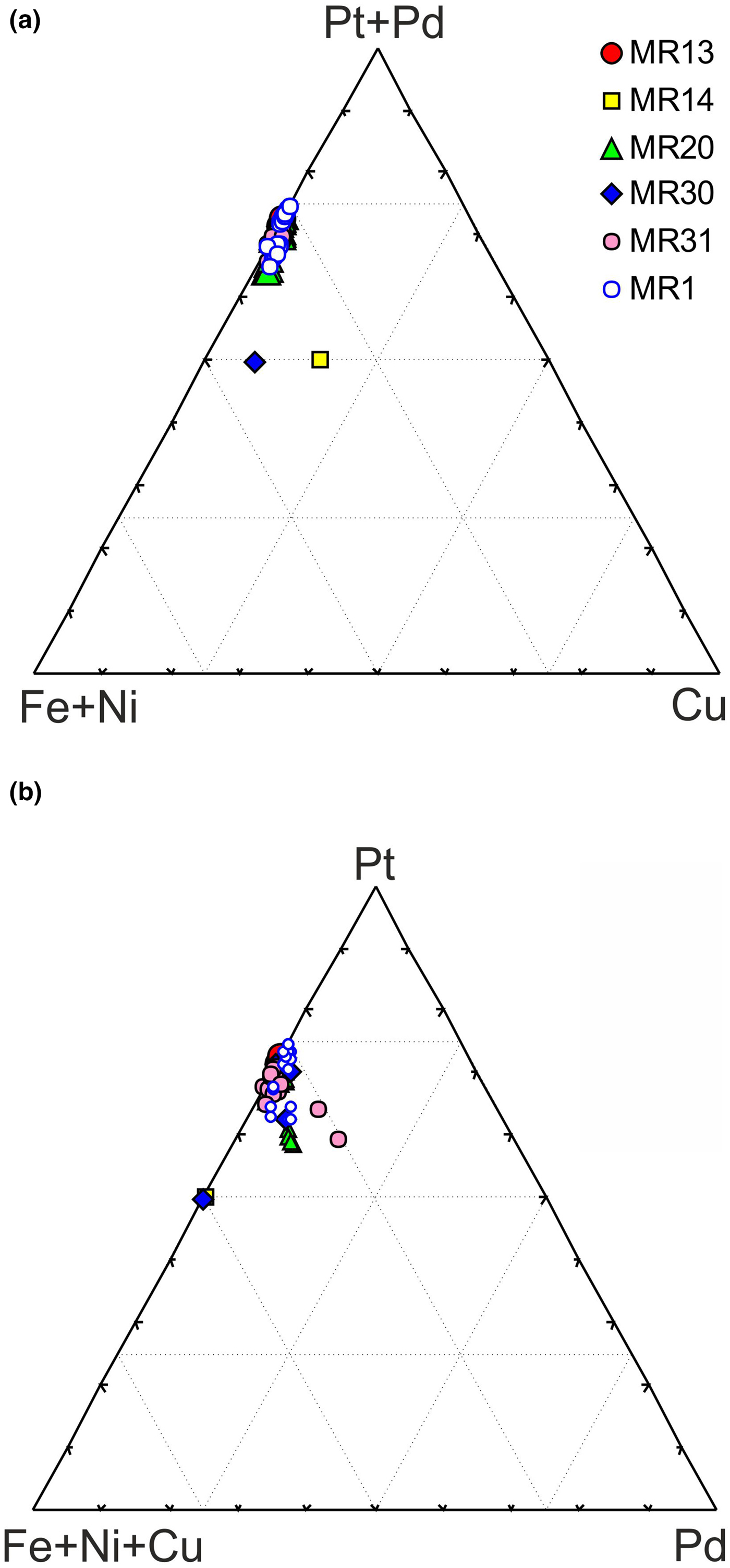
Pt–Fe alloys have a variable morphology: rounded and irregular grains in intergrowths with chalcopyrite (Figs 11j–l, 12a,b,i), as well as euhedral crystals (Fig. 5a–f). Pt–Fe alloys are typically found in the intergrowths with other PGM: atokite, zvyagintsevite (Fig. 12i), vincentite, vysotskite (Fig. 11j,l) and others. In some cases the inclusions of sulfides (one-, two-, or three-phase) are found in Pt–Fe alloys (Fig. 5). The Fe content of Pt–Fe alloys varies from 8.94 wt.% to 14.61 wt.% and the Ni content reaches up to 1.47 wt.% (Table S3), showing a continuous series of compositions from isoferroplatinum to ferrous platinum (Fig. 13a). Ferrous platinum prevails in the association studied over isoferroplatinum. Pt–Fe alloys are Pd rich (Fig. 13b); the concentration of Pd reaches up to 13.24 wt.% and corresponds to (Pt2.10Pd0.70)2.80(Fe1.14Ni0.06)1.20. Only two grains of tetraferroplatinum were found in the whole sample set (Fig. 13a).
Composition of Pt–Fe alloys in (a) Fe + Ni + Cu–Pt–Pd and (b) Fe + Ni–Pt + Pd–Cu diagrams.

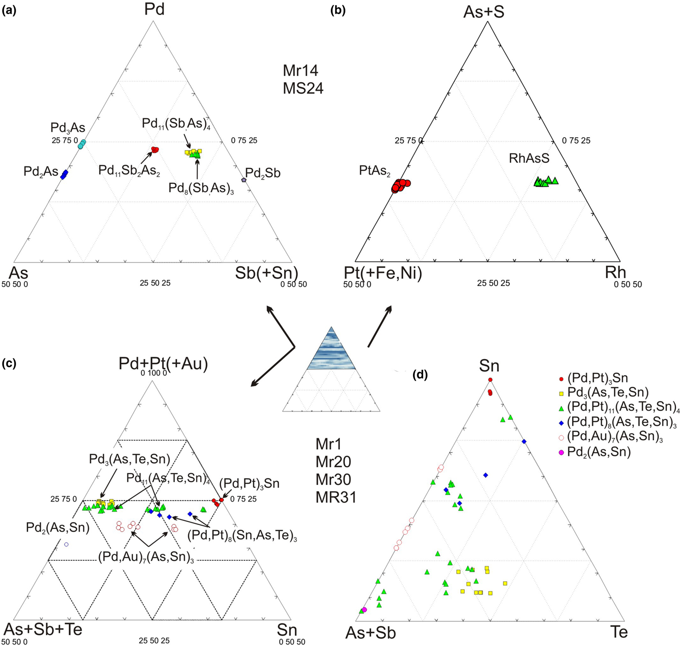
All the material investigated can be divided into three groups according to the dominant PGM assemblages. The Pd minerals of the Pd–Sb–As and Pt–Rh–As systems are characteristic only of the samples MR14, MR13 and MS24 of the first group (Figs 3, 11). These include palladoarsenide Pd2As, menshikovite Pd3Ni2As3, kotulskite Pd(Te,Bi), mertieite-I Pd11(Sb,As)4, mertieite-II Pd8(Sb,As)3, isomertieite Pd11Sb2As2, naldrettite Pd2Sb, palladoarsenide Pd2As (Fig. 14a), sperrylite PtAs2 and hollingworthite RhAsS (Fig. 14b). PGM do not contain the admixtures although mertieite-II can contain up to 2 wt.% Sn (Table S4). Hollingworthite usually is zoned with variable Pt/Rh ratios (Fig. 14b, Table 6). Sperrylite occurs as euhedral grains 5–30 µm (Fig. 3e) in contact with chromian spinel and ilmenite crystals. The large sperrylite crystals (30–100 µm) in sample MR14 contain droplet-shaped inclusions of sulfides (Fig. 5h–l) similar to those in Pt–Fe alloys in MR20. Sperrylite can contain up to 1.53 wt.% Rh as well as some S (Tables 3 and S4). An unnamed phase with a 7:3 stoichiometry corresponding to the formula (Pd,Au)7(As,Sn)3 with a regular Au admixture in the range 1.43–4.73 wt.% was found in three samples (identical analyses of 5 grains) (Fig. 14c,d; Table S4). The unnamed phases PdPt(As,Te,Sn)2 and (Ru,Rh)2(As,S)5 were found in the polished sections of the MS24 sample. Most probably, this is a fine grained mixture of two different minerals.
The composition of PGM and unnamed phases in in different systems.

Composition of PGM from sulfide segregations shown in Fig. 11.

*Total includes 1.16 wt.% Ru; ** total includes 3.13 wt.% Ru; *** total includes 1.43 wt.% Co; ‘–’ = below the detection limit.
§ Formulas
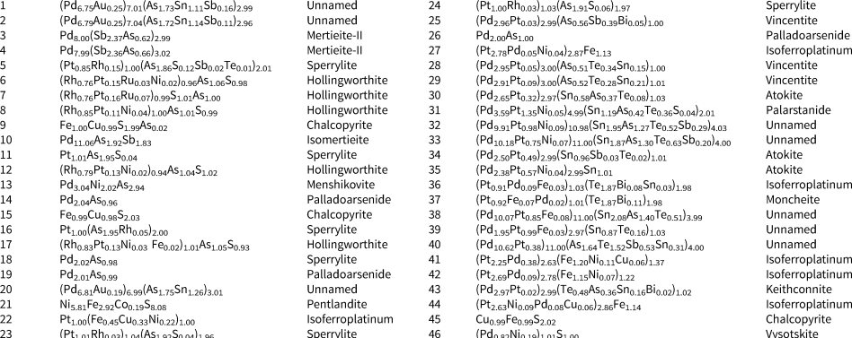
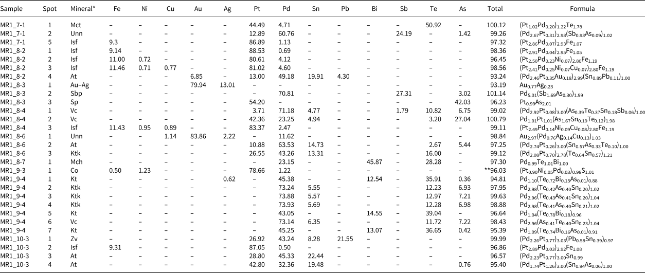
In the second group of samples MR20, MR30 and MR31, most of the Pd minerals have complex and multicomponent compositions. These are predominantly atokite with a high concentration of As and Te (Fig. 11g, 12e). The others are unnamed phases, namely Te and Sb analogues of vincentite, as well as an As analogue of mertieite-I and mertieite-II with varying proportions of As, Te, Sb and As (Fig. 14c,d; Tables 5, 6, 7, S4). They are commonly found in intergrowths with atokite and Pt–Fe alloys (Fig. 11g–l).
Composition of PGM from sulfide segregations illustrated in Fig. 12.

* Mct – moncheite, Sp – sperrylite, Unn – unnamed, Isf – isoferroplatinum (Pt–Fe alloys), At – atokite, Sbp – stibiopalladinite, Vc – vincentite, Mch – michenerite, Co – cooperite, Kt – kotulskite, Zv – zvyagintsevite, Ktc – keithconnite.
** Total includes 14.42 wt.% S.
‘–’ = below the detection limit.
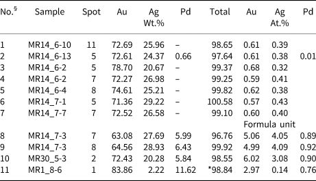
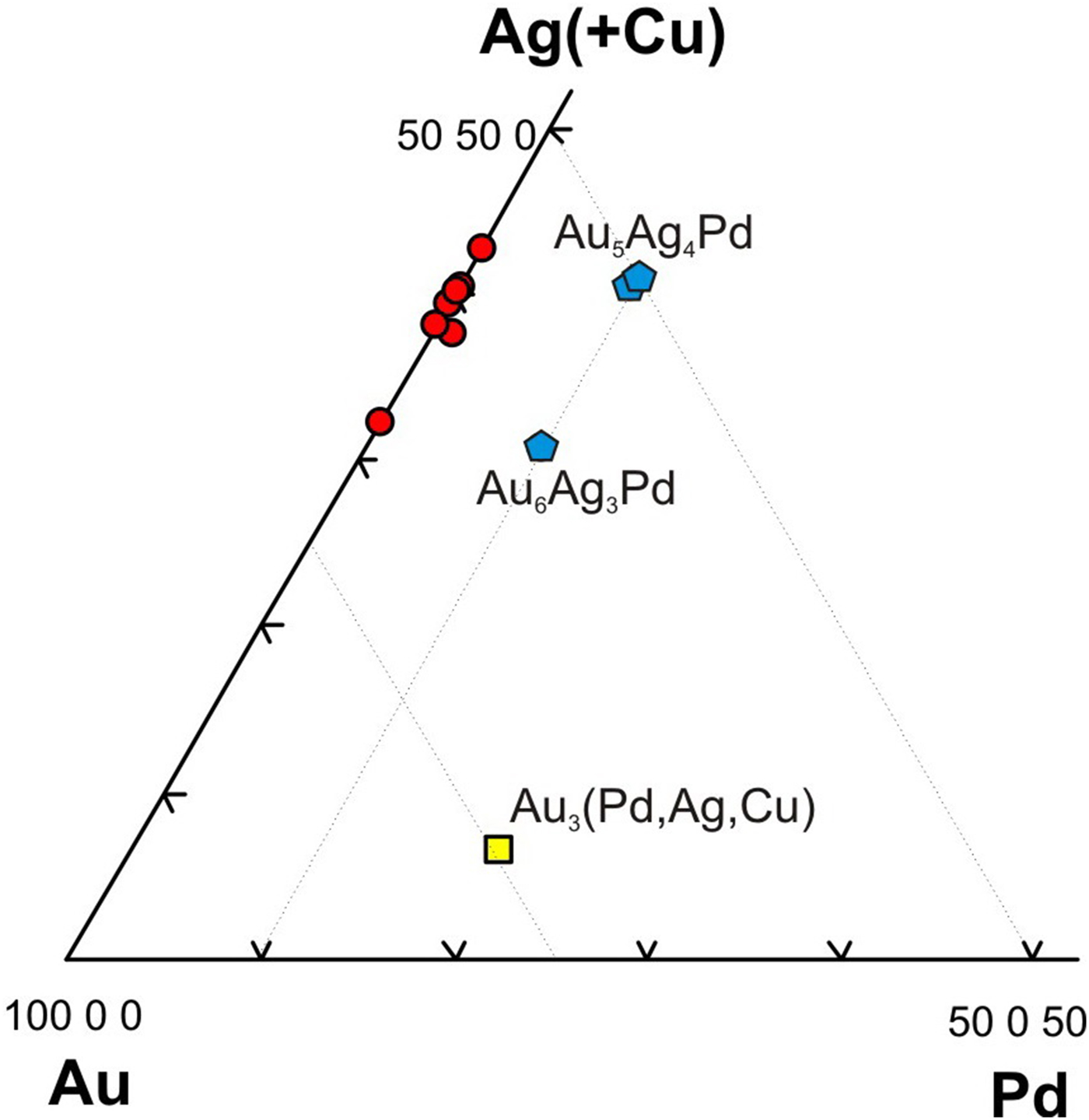
The PGM assemblage in sample MR1 is different from that described above, as it includes moncheite PtTe2, stibiopalladinite Pd5Sb2 intergrown with Pt–Fe and Au–Ag alloys; cooperite PtS and michenerite PdBiTe as separate grains (Fig. 12e, Table 8, no. 11). The compositions of all PGMs are given in the summary Table S4. In addition to Au–Ag alloys, Au–Au–Pd–Cu alloys were found in this association and are calculated on the formula Au6Ag3Pd, Au5Ag4Pd and Au3Pd (Table 8, no. 8–10). The first two are of several micrometres, one of them is an inclusion in pentlandite, the second in mertieite-II. The unknown composition Au5Ag4Pd is valid, as it is identical in different points on the grain. The third (Au3Pd) is a larger grain ~25 µm in size intergrown with atokite (Fig. 2e). Sudburyite, hollingworthite and cobaltite are found at their contacts. Hollingworthite is commonly surrounded by cobaltite and gersdorffite (Fig. 3f).
Composition of Au–Ag and Au–Ag–Pd alloys.

§ [1–7] Au–Ag solid solution; unnamed phases: [8,9] Au5Ag4Pd; [10] Au6Ag3Pd; [11] Au3(Pd,Ag,Cu).
* The total include Cu 1.14 wt.% (0.13 unit); ‘–’ = below the detection limit.
Discussion and conclusion
Features of chromian spinel
The chromian spinel from the low-sulfide horizon Noril'sk 1 is among the principal minerals, with which PGE mineralisation is associated (Sluzhenikin et al., Reference Sluzhenikin, Distler, Dyuzhikov, Kravtsov, Kunilov, Laputina and Turovtsev1994, Reference Sluzhenikin, Distler and Grigoryeva2016). For some of the samples the compositions of chromian spinel are generally similar to those reported previously for accessory chromian spinel from leucogabbro and segregations in gabbro-dolerite of the low-sulfide horizon (Genkin et al., Reference Genkin, Distler and Laputina1979 and Sluzhenikin et al., Reference Sluzhenikin, Distler, Dyuzhikov, Kravtsov, Kunilov, Laputina and Turovtsev1994), as well as to the compositions of chromian spinel from picritic gabbro-dolerites of the layered series (Ryabov et al., Reference Ryabov, Shevko and Gora2001) (Fig. 7b). These compositions fill the gaps in the database of the spinel compositions from the flood basalt provinces worldwide (Barnes and Roeder, Reference Barnes and Roeder2001).
The chromian spinels are enriched in TiO2, up to 13.94 wt.%. Our data do not reveal a clear correlation between TiO2 and Fe3+/(Cr + Al + Fe3+) as was shown for the chromian spinel from the picrite of Noril'sk 1 (Barnes and Kunilov, Reference Barnes and Kunilov2000) (Fig. 7d) and continental mafic intrusions (Barnes and Roeder, Reference Barnes and Roeder2001). However, a pronounced positive correlation exists between TiO2 and Fe2+/(Mg + Fe2+) similar to that of the picritic and taxitic gabbro-dolerites of the layered series (based on data of Sluzhenikin et al., Reference Sluzhenikin, Distler, Dyuzhikov, Kravtsov, Kunilov, Laputina and Turovtsev1994). However, these spinels are characterised by lower values of these parameters (Fig. 7). Positive correlation of TiO2 with Fe2+ is termed the ‘ilmenite trend’ as opposed to the ‘titanium magnetite trend’ from picritic gabbro (Chayka et al., Reference Chayka, Kamenetsky, Izokh, Zhitova, Tolstykh, Yakich and Lobastov2019). The low degree of oxidation of chromian spinel and the ilmenite trend indicate reducing conditions of crystallisation, which could be due to the interaction of the parental magma with the black shales of the host rocks and fluid regime (e.g. Ryabov et al., Reference Ryabov, Shevko, Simonov and Anoshin1996, Reference Ryabov, Shevko and Gora2001).
As shown previously, the composition of chromian spinels (as well as other minerals) in volcanic rocks is dependent on the magma from which they crystallise (Arai, Reference Arai1992); in particular, the abundance of TiO2 in magmatic chromian spinel depends on the content of this oxide in the parental melt (Kamenetsky et al., Reference Kamenetsky, Crawford and Meffre2001). Ilmenite in the association studied occurs as sub-micrometre inclusions and large crystals. Volcanic rocks (picrite of the Gudchikhinsky Suite) of the Noril'sk region also contain chromian spinel with concentrations of TiO2 up to 2.8 wt.% (Krivolutskaya, Reference Krivolutskaya2014). The unusually high Ti content in the chromian spinel analysed from the low-sulfide horizon of Noril'sk 1 could be indicative of the strong Ti-enrichment of the parental magma. However, most of the chromian spinel examined are Cr-rich and depleted in Al, which is consistent with the incompatibility between Al and Ti in spinels, while extreme TiO2 enrichment of some chromian spinel grains (as well as some other outstanding features) will be discussed in future studies.
The typical Fe3+–Ti trend can be controlled by: (1) the evolution of the spinel composition during fractional crystallisation of pyroxene and plagioclase in the parental magma and (2) the post-cumulus modification of chromian spinel during reaction with the evolving intercumulus liquid (Roeder and Campbell, Reference Roeder and Campbell1985; Scowen et al., Reference Scowen, Roeder and Helz1991; Cawthorn et al., Reference Cawthorn, de Wet, Hatton and Cassidy1991; Barnes and Kunilov, Reference Barnes and Kunilov2000; Barnes and Roeder, Reference Barnes and Roeder2001). The absence of a positive correlation between Fe3+ and TiO2 and the presence of a distinct positive correlation with Fe2+ and TiO2 are unique features of these rocks. The Fe3+content varies in different samples of chromian spinel. The higher values of Fe3+/(Cr + Al + Fe3+) are characteristic of the MR20 and MR31 samples similar to those of picrites and picritic gabbro-dolerites of the layered series of Noril'sk 1 and Talnakh (Sluzhenikin et al., Reference Sluzhenikin, Distler, Dyuzhikov, Kravtsov, Kunilov, Laputina and Turovtsev1994; Barnes and Kunilov, Reference Barnes and Kunilov2000; Ryabov et al., Reference Ryabov, Shevko and Gora2001) (Fig. 7a,c,e). Barnes and Tang (Reference Barnes and Tang1999) determined that the Jinchuan chromites associated with sulfides are Ti rich and depleted significantly in Ni (similar to the studied chromian spinels) in comparison to chromite in the barren (sulfide-free) intrusions.
The multiphase droplet-like silicate inclusions can provide a clue to several petrological problems concerning the origin of low-sulfide ores. Hence, the genesis of chromian spinel and these inclusions are only briefly considered in this work and will be discussed elsewhere.
Composition of base-metal sulfides
The diagrams (Vaughan and Craig, Reference Vaughan and Craig1978; Barton and Skinner, Reference Barton, Skinner and Barnes1967; Ehlers, Reference Ehlers1972; Kaneda et al., Reference Kaneda, Takenouchi and Shoji1986; Peregoedova, Reference Peregoedova1999; Kolonin et al., Reference Kolonin, Orsoev, Sinyakova and Kislov2000) (Fig. 9a,b) indicate that the concentration of Ni in pentlandite and the concentration of S in pyrrhotite increase with an increasing of S fugacity in the ore-forming system and a decreasing of temperature (from 600 to 400°C). It has been substantiated experimentally that there are several ways to form pentlandite (Kitakaze et al., Reference Kitakaze, Mzchida and Komatsu2016). However, Likhachev and Kukoev (Reference Likhachev and Kukoev1973) showed that pentlandite in Noril'sk-Talnakh ores occur as a decomposition product of either monosulfide solid solution (MSS) (in the case of Fe rich ores) or intermediate solid solution (ISS) (in the case of Cu rich ores) regardless of the content of Cu and Ni in melt at temperatures below 600°C. Pentlandite has always been found as the lamellar inclusions in pyrrhotite, both in the sulfide segregations, and in the droplet-like inclusions inside PGMs in the samples studied. Therefore, we assume that all pentlandite grains in the associations examined formed by exsolving from MSS.
Globules of sulfides have been described previously in disseminated ores of picritic gabbro-dolerites (Czamanske et al., Reference Czamanske, Kunilov, Zientek, Cabri, Likhachev, Calk and Oscarson1992; Distler et al., Reference Distler, Sluzhenikin, Laputina and Kulagov1996; Barnes et al., Reference Barnes, Cox and Zeintec2006; Dodin et al., Reference Dodin, Sluzhenikin and Bogomolov2009). They occur in the olivine orthocumulate as droplets of sulfide melt. The distinctive differentiated globular sulfide ores have textures indicative of accumulation of sulfide globules attached to vapour bubbles within the olivine orthocumulates at the cumulus stage (Barnes et al., Reference Barnes, Le Vaillant, Godel and Lesher2019).
The feature of the investigated association is the occurrence of sulfide droplet-like inclusions in the Pt–Fe alloys, sperrylite and mertieite-II, which have not been described previously in the Noril'sk deposits. However, the PGM grains with a skeletal morphology containing the veinlets of sulfide inclusions (not droplets) have been described previously and interpreted as metacrystals (metasomatic crystals grown in other solid minerals) (Genkin and Evstigneeva, Reference Genkin and Evstigneeva1986). We suggest that the droplet-like sulfide inclusions in PGM have crystallised from trapped sulfide melt under closed-system conditions. The captured sulfide droplets are fragments of a sulfide melt fractionated to varying degrees by the crystallisation of early sperrylite and isoferroplatinum, which, in its turn, indicates that the crystallisation of these PGM took place earlier than sulfides in trapped droplet-like inclusions. It can be assumed that the sulfide melt captured during the growth of sperrylite crystals did not contain enough copper to crystallise chalcopyrite, therefore only the pentlandite–pyrrhotite association is observed in sperrylite. The sulfide melt captured by the Pt–Fe alloys was already more fractionated compared to that captured by sperrylite, as chalcopyrite is a component of droplet-like inclusions, but much less common than pyrrhotite and pentlandite. The sulfide droplets differ from the previously described globules by the lack of separation of sulfide into two phases: Fe-rich and Cu-rich inside the droplet (Barnes et al., Reference Barnes, Le Vaillant, Godel and Lesher2019). They include sulfides, formed from melt, fractionated to varying degrees.
The Fe/Ni ratios of pentlandite reflect the thermodynamic conditions of formation (Kolonin et al., Reference Kolonin, Orsoev, Sinyakova and Kislov2000; Kosyakov et al., Reference Kosyakov, Sinyakova and Shestakov2003), including sulfur fugacity (f S2). The Fe/Ni ratios in natural pentlandite decrease with the increasing f S2 (Kaneda et al., Reference Kaneda, Takenouchi and Shoji1986). Compositions of pentlandite from the low-sulfide horizon of Noril'sk 1 varies from those enriched in Fe to Ni-rich ones that are shown in Fig. 8. The Fe-rich pentlandite is associated with troilite in a paragenesis (I) found in sulfide inclusions in sperrylite, exclusively. The higher content of Ni in pentlandite and S in pyrrhotite are characteristic of sulfide inclusions in Pt–Fe alloys (paragenesis II). The sulfide segregations in samples MR30 and MS24 are composed of the progressively S-rich paragenesis III that includes pyrite. The sulfides richer in Ni and S, including pyrite and millerite, comprise paragenesis IV that was documented in sample MR31. Highly reducing conditions favour sulfides richer in Ni (Barnes et al., Reference Barnes, Godel, Gurer, Brenan, Robertson and Paterson2013). Thus, the evolution of sulfide melt composition and the change of the mineral parageneses with the increasing sulfur and oxygen fugacity are demonstrated by these data.
Sperrylite is probably the earliest PGM mineral to form as it captures the least fractionated sulfide liquid during crystallisation. Sulfide droplet-like inclusions in PGM are rare, similar inclusions in sperrylite were noted earlier at the Vilgrid (Yukon) deposit (Cabri, Reference Cabri and Cabri2002). The Ni/(Ni + Fe) ratio in pentlandite (k) varies from 0.46 to 0.65 in different associations (Fig. 9). According to Kolonin et al. (Reference Kolonin, Orsoev, Sinyakova and Kislov2000) ‘k’ variation depends on the change of logf S2, at the pentlandite stability temperature of 610°C (Kullerud, Reference Kullerud1962; Vaughan and Craig, Reference Vaughan and Craig1978). It can be assumed that the pentlandite and associated sulfides were crystallised at logf S2 ≈ –10.5 in the droplet-like inclusions from sperrylite, logf S2 ≈ –9.5 in the droplet-like inclusions from Pt–Fe alloys, and logf S2 from –9 to –7.7 in the sulfide segregations. The most fractionated sulfide liquid (k = 0.66 in pentlandite) was captured by mertieite-I, which indicates its crystallisation at the later stages of the evolution of the ore-forming system.
In this system, there is a regular (not random) change in the compositions of pyrrhotite and pentlandite from inclusions in sperrylite to inclusions in isoferroplatinum and to sulfide grains and segregations in intergrowths with PGM. This change is consistent with the change in parageneses (Fig. 8) during an increase of sulfur content. The observed evolution is consistent with the thermodynamic data given above.
In general, it can be concluded that the captured sulfide droplet-like inclusions are composed of a low-sulfur association (troilite, Fe-enriched pentlandite and chalcopyrite with Fe > Cu). A similar association is characteristic of disseminated ores from picritic gabbro-dolerites of the Noril'sk 1 (Tolstykh et al., Reference Tolstykh, Shvedov, Polonyankin and Zemlyansky2017). Sulfides from the sulfide segregations belong to a high-sulfur association, which include chalcopyrite, pyrite, monoclinic pyrrhotite, millerite and Ni-rich pentlandite. A similar ‘low-temperature association’ (chalcopyrite + millerite + pyrite) is characteristic of the low-sulfide horizon of the Talnakh intrusion (Sluzhenikin et al., Reference Sluzhenikin, Distler, Dyuzhikov, Kravtsov, Kunilov, Laputina and Turovtsev1994). This has also been described in disseminated ores of olivine gabbro-dolerites in the lower part of layered section of the Noril'sk 1 deposit (Tolstykh et al., Reference Tolstykh, Shvedov, Polonyankin and Zemlyansky2017).
Features of PGE mineralisation
Platinum-group element mineralisation of the low-sulfide horizon of Noril'sk 1 has a number of the specific features. The PGM are distributed very unevenly. In some samples, isoferroplatinum is dominant among the Pt minerals, whereas in others sperrylite is the major phase. Isoferroplatinum, as a rule, is a minor mineral of the Noril'sk deposits but dominates in massive pyrrhotite ores of the Kharaelakh intrusion (Komarova et al., Reference Komarova, Kozyrev, Siminov, Lulko and Cabri2002; Kozyrev et al., Reference Kozyrev, Komarova, Emelina, Oleshkevich, Yakovleva, Lyalinov, Maximov and Cabri2002), and in the concentrates of disseminated ore (Genkin and Evstigneeva, Reference Genkin and Evstigneeva1986). Ferrous platinum, close to Pt2Fe is also characteristic of disseminated ores (Distler et al., Reference Distler, Sluzhenikin, Krivolutskaya, Turovtsev, Golovanova, Mokhov, Cabri, Knauf and Oleshkevich1999) and the low-sulfide horizon (Sluzhenikin et al., Reference Sluzhenikin, Distler, Dyuzhikov, Kravtsov, Kunilov, Laputina and Turovtsev1994) where it was described as a mixture of PtFe and Pt3Fe.
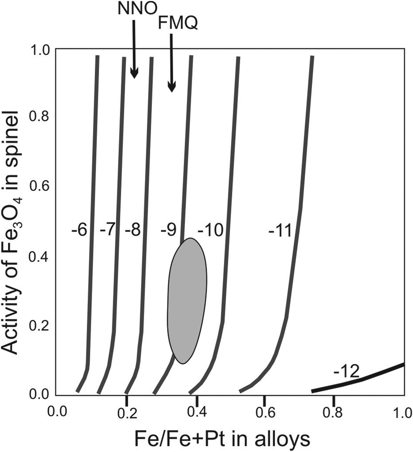
The composition of the alloy, coexisting with chromite at temperatures of 1200–1300°C, calculated from thermodynamic data, agrees with the composition of Pt–Fe alloy found in experiments (Roeder and Jamieson, Reference Roeder and Jamieson1992). The alloy composition is quite sensitive to variation in oxygen fugacity. It is believed that basaltic melts crystallise at oxygen fugacities within one or two orders of magnitude of the oxygen fugacity (f O2) of the FMQ buffer. The composition of Pt–Fe alloy that can coexist with a typical magmatic chromian spinel at the FMQ buffer (logf O2= –(8–9) is Fe/(Fe + Pt) = 0.20–0.25. The lower the oxygen fugacity, the higher the Fe/(Fe + Pt) of the alloy (Roeder and Jamieson, Reference Roeder and Jamieson1992). Consequently, the ferrous platinum of the samples analysed with a Fe/(Fe + Pt) range of 0.26–0.37 crystallises at lower f O2 (logf O2 ≈ –(9–10)) than isoferroplatinum Pt3Fe which crystallise in conditions at the FMQ buffer (Roeder and Jamieson, Reference Roeder and Jamieson1992) (Fig. 15). Decrease of oxygen fugacity (an increase of reducing conditions) during the development of the ore-forming system makes it possible to assume that the evolution of Pt–Fe alloys in the samples studied from isoferroplatinum to ferrous platinum is due to the impact of reducing fluids, the source of which might be the sedimentary rocks of the Siberian platform cover (Ryabov and Lapkovsky, Reference Ryabov and Lapkovsky2010; Ryabov et al., Reference Ryabov, Shevko and Gora2014). The reducing conditions are in agreement with the compositions of chromian spinel, which show a positive correlation between Ti and Fe2+ contents. Such changes in the composition of Pt–Fe alloys differ from the trend of their development in the Uralian–Alaskan type complexes: i.e. from ferrous platinum to isoferroplatinum, which in contrast is caused by an increase in oxygen activity in their evolution, as shown earlier at the Nizhny Tagil massif (Tolstykh et al., Reference Tolstykh, Kozlov and Telegin2015).
Activity of Fe3O4 in chromian spinel versus the atomic Fe/(Fe + Pt) in alloy at 1200°C by Roeder and Jamieson (Reference Roeder and Jamieson1992). The shaded area is the approximate crystallization conditions of the Pt–Fe alloys investigated based on their compositions.

This explanation is reasonable, as Fe and Pd contents are correlated positively (r = 0.77) (Table S3). Both elements accumulate in Pt–Fe alloys during the evolution of the ore-forming system: due to an increase in the reducing conditions (Roeder and Jamieson, Reference Roeder and Jamieson1992), and the fractionation of the PGE in these systems (Johan et al., Reference Johan, Slansku and Kelly2000).
The genesis of sperrylite is debated in the literature. There is an opinion that sperrylite can not crystallise at high temperatures, as As and Pt do not reach a saturation in natural magmatic sulfide melts (Bai et al., Reference Bai, Barnes and Baker2017). In contrast, it has been shown that direct crystallisation of sperrylite is possible from an S-undersaturated basaltic magma (Maier et al., Reference Maier, Rasmussen, Fletcher, Godel, Barnes, Fisher and Yang2015). The factor required to decrease the solubility of the Pt and As in basalt melt and crystallisation of sperrylite is a reduction in f O2 of FMQ to FMQ-2 in basic magma (Canali et al., Reference Canali, Brenan and Sullivan2017). Therefore, sperrylite formed in reducing conditions, and is probably a high-temperature magmatic mineral (the first among PGM), which captured the droplets of the least fractionated sulfide liquid (S-poor pyrrhotite and Ni-poor pentlandite) in comparison with the melt, which was captured by later Pt–Fe alloys.
The magmatic nature of the sperrylite is not consistent with the genesis of this mineral as previously considered for Noril'sk ores. Most authors consider sperrylite to be a late-stage pneumolitic mineral (Spiridonov, Reference Spiridonov2010) or ‘metacrystals’ (Genkin and Evstigneeva, Reference Genkin and Evstigneeva1986). A hydrothermal genesis is also considered for Imandra sperrylite (Barkov and Fleet, Reference Barkov and Fleet2004), but the low-temperature sperrylite from Noril'sk described by these authors, was probably formed from a fractionated sulfide melt (Craig and Kullerud Reference Craig and Kullerud1969) compared with the high-temperature sperrylite investigated here, which crystallised from silicate melt.
Experimental data show that the identified phases of Ru and Rh [RhAsS, (Ru,Rh)2As5], antimonides [Pd2Sb and Pd(Sb,Te)], and arsenides (Pd2As, Pd3As) might be stable up to 790°C (Makovicky, Reference Makovicky and Cabri2002) and the Pd3As synthetic phase is stable up to 820°C (Raub and Webb, Reference Raub and Webb1963). These compounds are associated with sperrylite PtAs2, Cr-rich сhromian spinel (Cr# = 0.85–0.88) and troilite (MR14, MS24) whereas the numerous complex phases rich in Te–Sn–Sb–As are associated with a Pt–Fe alloy.
Abundant phases (Pd,Pt)3(As,Sn,Te,Sb) (possibly vincentite–atokite solid solutions) have been described previously in the Noril'sk deposits: Pd3(As,Te), Pd3(Sn,As), Pd3(As,Sb,Sn,Te) (Sluzhenikin et al., Reference Sluzhenikin, Distler, Dyuzhikov, Kravtsov, Kunilov, Laputina and Turovtsev1994; Kovalenker et al., Reference Kovalenker, Genkin, Evstigneeva and Laputina1974; Genkin, Evstigneeva, Reference Genkin and Evstigneeva1986; Distler, Reference Distler, Sluzhenikin, Krivolutskaya, Turovtsev, Golovanova, Mokhov, Cabri, Knauf and Oleshkevich1999). They can also be compared with Pd3As and Pd3(Te,As) phases reported in other occurrences (Kucha, Reference Kucha1984; Johan et al., Reference Johan, Slansky and Ohnenstetter1991). These phases also occur in association with grains of As- and Sn-dominant potential analogues of mertieite-I and Sn-dominant analogues of mertieite-II (unnamed phases) (Table 5, S4). The considerable variability of the compositions indicates that these solid solutions crystallised at a high activity of all these element ligands (Te, Sn, Sb and As) from the evolved sulfide melt.
We suggest that the crystallisation of PGM started at >800°C and logf S2 < –10.5 for sperrylite and logf S2 ≈ –(9–10) for isoferroplatinum as shown in Fig. 9 at f O2 conditions, at a much lower FMQ buffer. Palladium minerals, as binary compounds (such as Pd2Sb, Pd2As or Pd3As), which are stable at ≈800°C, crystallised later. Eventually, the complex and multicomponent compounds became stable at a lower temperature with an increasing activity of element ligands.
Three Au- and Pd-containing unnamed phases with the compositions Au5Ag4Pd, Au6Ag3Pd and Au3(Pd,Ag,Cu) (Table 8) require additional studies. The first phase is hosted in pentlandite, the second in mertieite-II and the phase Au3(Pd,Ag) is intergrown with atokite. Numerous grains of solid solutions in Ag–Au–(Pt + Pd) and Au–Cu–(Ag,Pt,Pd) systems have been described in the Noril'sk ore deposits (Sluzhenikin and Mokhov, Reference Sluzhenikin and Mokhov2015), but there are no analogous phases among them. The Au3Pd phase has also been reported previously in an alluvial Au–Pd–Pt deposit in northern Brazil (Cabral et al., Reference Cabral, Tupinamba, Lemann, Kwitko-Ribeiro and Vymazalova2008). However, the Au3Pd phase with a cubic Cu3Au-type crystal structure is known in the Au–Pd synthetic system to be stable at temperatures below 850°C (Okamoto and Massalski, Reference Okamoto and Massalski1985). In contrast, the phases Au5Ag4Pd, Au6Ag3Pd can also randomly have a stoichiometric relationship, and be a part of Au–Ag solid solutions in which there is substitution of Pd for Ag, as these compounds lie on the same trend of Au–Ag compositions (Fig. 16).
Composition of Au–Ag and Au–Ag–Pd alloys.

Conclusions
The evolution of the mineral association studied in the low sulfide horizon of the Noril'sk 1 intrusion is associated with reducing conditions during its formation. This situation resulted in: (1) a positive correlation of TiO2 and Fe2+ in chromian spinel; (2) crystallisation of high-temperature sperrylite from silicate melt, which is possible under reducing conditions (f O2 of FMQ to FMQ-2) in basic magma before the start of crystallisation of sulfides; (3) crystallisation of ferrous platinum (Fe-rich Pt–Fe alloys) under conditions of logf O2 ≈ –(9–10).
The phases present in every inclusion formed under closed-system conditions. At the same time, the captured sulfide melt has evolved in the direction of an increasing sulfur fugacity. A general trend of evolution of captured melt is: troilite + pentlandite (Fe>Ni) in sperryllite to monoclinic pyrrhotite + pentlandite (Ni≈Fe) + chalcopyrite in Pt–Fe alloys; Paragenesis in sulfide aggregates are more evolved: pyrrhotite + pyrrhotite (Ni>Fe) + chalcopyrite in some samples and pyrite + pentlandite (Ni≫Fe) + millerite in others. The pentlandite from droplet-like inclusions in mertieite-II has the most Ni-rich composition. Probably this mineral was formed from the residual sulfide melt during the final crystallisation stage.
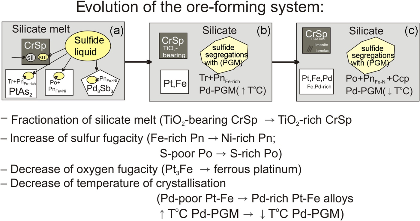
The data presented in this paper indicate that the evolution of the ore-forming system occurred as follows:
(1) The sulfide liquid was captured during progressive crystallisation of the PGM including the earliest sperrylite, followed by isoferroplatinum, and finally mertieite-I. The compositions of the captured sulfide liquid evolved at increasing f S2 as reflected by pyrrhotite being progressively enriched with sulfur, and pentlandite with nickel. Sulfides from the sulfide segregations in taxitic gabbro of the low-sulfide horizon have more evolved compositions with respect to those trapped as the inclusions in sperrylite and isoferroplatinum. This observation also supports the earlier crystallisation of these PGM prior to the crystallisation of segregated sulfides.
(2) The crystallisation of sperrylite begins at a temperature of more than 800°C, in conditions of f O2 of FMQ to FMQ-2 in basic magma and logf S2 <–10.5 (by sulfides in drops). Pt–Fe alloys subsequently crystallised at logf S2 ≈ –(9–10) before the bulk crystallisation of sulfide. Palladium arsenides and antimonides are stable at temperatures below 800°C and crystallise later than Pt–Fe alloys. At the final stage, complex and multicomponent compounds of diverse stoichiometries become stable with an increase in the activity of semi-metals (Te, Sn, Sb and As) in a sulfide melt at temperatures <600°C (Fig. 17).
(3) At this stage of the research, low-Ti chromian spinels were crystallised at the earliest stages of magmatism whereas those enriched in Ti, hosting ilmenite lamellae and exsolutions were formed probably due to a reaction with a high-Ti inter-cumulus liquid.
Evolution of the ore-forming system in the low-sulfide horizon of the Noril'sk 1 intrusion. Ccp - chalcopyrite, CrSp - chromian spinel, Pn - pentlandite, Po - pyrrhotite, Tr - troilite.

Acknowledgements
The authors thank N.S. Karmanov, M.V. Khlestov and E.N. Nigmatulina for their help with scanning microscopy and microprobe studies at IGM SB RAS, and the geologists from Noril'sk Nickel mining company: S.G. Snisar, I.N. Tushentsova, A.A. Dan'chenko, E.V. Sereda and others for helping during the fieldwork on the Noril'sk deposits.
The comments by Associate Editor B. O'Driscoll, T. Evstigneeva and anonymous reviewers are greatly appreciated; they helped to improve this paper. The studies were carried out within the framework of the state assignment of the Institute of Geology and mineralogy Siberian Branch of Russian Academy of Sciences, project No. 0330-2016-0003. The field work was partly supported by RFBR project No. 16-05-00945; the financial assistance from the RFBR projects No. 19-05-00316, 19-05-00181 and grant of Russian Scientific Foundation No. 19-17-13013.
Supplementary material
To view supplementary material for this article, please visit https://doi.org/10.1180/mgm.2019.47