INTRODUCTION
Dielectric resonators (DRs) are nonmetallic object which functions similar to metallic cavities [Reference Long, Allister and Shen1]. The DR can be used as radiating element and act as a DR antenna with different excitation methods such as microstrip line, coaxial probe, and aperture coupling and co-planer waveguide feed. Dielectric resonator antennas (DRAs) are available in many basic shapes such as cylindrical, rectangular, spherical, hemispherical, and triangular geometry etc. [Reference Richtinyer2, Reference Petosa3]. It has several attractive features such as small size, low profile, high radiation efficiency, flexible feed arrangement, simple geometry structure, light weight, low cost, a wide range of material dielectric constant which gives more flexibility to the antenna designer [Reference Richtinyer2–Reference Mongia5]. Triangular dielectric resonator antennas (TDRA) is more compact in size compared with rectangular and circular disc DRAs [Reference Lo, Leung, Luk and Yung6].
For DRAs, bandwidth enhancement is a major design consideration for practical application. To enhance the bandwidth of DRAs, there are several techniques such as changing the aspect ratio of DRA [Reference Petosa3], varying the dielectric constant of the material [Reference Kishk, Glisson and Zhang7], sectoring and splitting of the basic structure [Reference Kishk and Glisson8] by using stacked DRAs and multi-segments [Reference Kishk and Glisson8, Reference Shum and Luk9], multi-element [Reference Kishk, Glisson and Zhang7], introducing air-gap between ground and the DRA element [Reference Junker, Kishk, Glisson and Kajfez10]. Inserting low dielectric material below the high dielectric material also leads to improvement in bandwidth [Reference Petosa, Simons, Siushansian, Ittipiboon and Cuhaci11].
For monopole type radiation pattern, some studies on DRAs are reported in the literature. The dielectric ring resonator antenna is used for constructing small and compact monopole like radiation pattern and has been studied [Reference Mongia, Ittipiboon, Bhartia and Cuhaci12]. Multi-element cylindrical DRA and half split hemispherical DRAs have been investigated for monopole like radiation pattern with wide bandwidth by Guha and Antar [Reference Guha and Antar13, Reference Guha and Antar14], which shows an enhancement in bandwidth by introducing multi-element and splitting basic structure. Similarly, four elements rectangular DRA excited with coaxial probe gives 35.25% bandwidth with monopole radiation pattern investigated for bandwidth enhancement [Reference Gangwar, Singh and Kumar15]. Further, for X-Band application three element dual segments TDRA with monopole like radiation pattern has been investigated through simulation and experimentally [Reference Gupta, Gangwar and Singh16]. Segmentation of hemispherical DRA was investigated in multi-element composite forms with monopole type radiation for wideband application [Reference Guha, Gupta, Kumar and Antar17]. Half hemispherical DRA with array of slot has been introduced with 29% bandwidth for wideband application, by increasing the probe length a shift in resonance frequency has been observed and it behaves like monopole DRA [Reference Mukharjee, Patel, Reddy and Mukharjee18].
This paper presents the simulation and experimental studies of a four element TDRA, which is fed by a 50 Ω coaxial probe feed. The simulation study of the proposed antenna array is carried out using commercially available Ansoft HFSS and CST Microwave Studio simulation software. The simulation and measured results are in good agreement for the proposed antenna. The proposed antenna input characteristics has been compared with single element TDRA and found enormous enhancement in bandwidth. The proposed antenna produces a monopole like radiation pattern over entire bandwidth having a resonant frequency of 5.45 GHz.
CONFIGURATION OF ANTENNA DESIGN
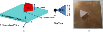
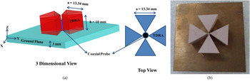
The geometry of the single element TDRA and the proposed four elements TDRA is shown in Figs 1 and 2. The dimension of each DR of the structure is a = 13.34 mm and height h = 10 mm. The dielectric constant of the material is ε r = 12 (TCI ceramics Inc, USA, K-12, tan δ = 2.0 × 10⁻⁴) used for each element of the proposed antenna. The DR elements of the composite structure are packed together in a compact way on a metallic ground plane of dimensions 50 mm × 50 mm × 3 mm. The proposed antenna has been excited by a 50 Ω coaxial probe, which touches the corner edge of all the four elements of the TDRA as shown in Fig. 2. The main reason for taking TDRA is that for a given height and resonant frequency, it offers a smaller area than either a cylindrical or rectangular DRA [Reference Lo and Leung19]. Thus, it is beneficial for an antenna array application. For a larger range of space available between TDRA elements gives enhancement in bandwidth.
(a) Geometry, (b) fabricated prototype of single element TDRA.

(a) Geometry, (b) fabricated prototype of proposed four elements TDRA.

RESULTS AND DISCUSSION
A) Return loss and Input Impedance versus frequency curve
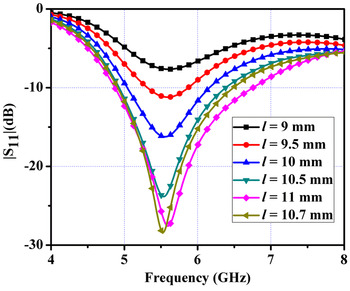
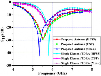
The simulated |S 11| versus frequency curve has been optimized for different probe height (l) shown in Fig. 3. The height of the probe is found to be 10.7 mm above the ground plane, through extensive simulation for minimum return loss of the proposed antenna. Similarly for single element TDRA probe height is obtained 10.8 mm above the ground plane. The simulation study of |S 11| versus frequency curve of the proposed antenna and single element TDRA has been carried out using Ansoft HFSS and CST Microwave Studio simulation software. The |S 11| versus frequency curves has been experimentally measured using Vector Network Analyzer (VNA; ROHDE & SCHWARZ- 10 MHz–20 GHz. ZVM). The simulated and experimental return loss versus frequency curves of the proposed four elements and the single element TDRA are presented in Fig. 4. From Fig. 4, simulated and measured resonant frequency, operating frequency range, and the percentage bandwidth of the proposed antenna as well as single element TDRA are extracted and shown in Table 1. From Fig. 4 and Table 1, it can be observed that there is good agreement with simulation and measured results. The bandwidth of the proposed antenna is found higher than the single element TDRA this is due to reduction in the effective dielectric constant of the proposed DRA and also due to higher surface volume area for radiation.
Effect of variable probe length l for the |S 11| characteristics of proposed antenna.

Comparison of simulated and measured |S 11| parameter of the proposed four elements and single element TDRA (same dimension).

Resonant frequency and return loss performance of proposed four element and single element TDRA.

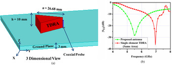
The performance of proposed antenna has been compared with single element TDRA (same area as proposed antenna) shown in Fig. 5. It is apparent from Fig. 5, that the single element TDRA (a = 26.68 mm) of same area has less operating bandwidth and higher resonant frequency similar to single element TDRA (a = 13.34 mm) of same dimension compared with proposed antenna.
(a) Geometry of single element TDRA (same area of proposed antenna), (b) comparison of |S 11| parameter of the proposed antenna and single element TDRA (same area).

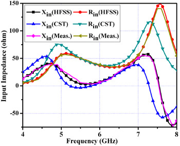
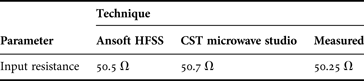
The input impedance versus frequency characteristic of the proposed antenna has been investigated using Ansoft HFSS and CST Microwave Studio simulation software. The input impedance of the proposed antenna is also measured experimentally with the help of VNA (ROHDE & SCHWARZ- 10 MHz—20 GHz. ZVM). The simulated and measured input impedance versus frequency curve of the proposed antenna is shown in Fig. 6. Simulated and measured value of input resistance is extracted and given in Table 2. From Fig. 6 and Table 2, it can be observed that there is good agreement with simulated and measured results and also their values are very close to 50 Ω impedance of coaxial probe feed.
Variation of input impedance versus frequency of proposed four elements TDRA.

Input resistance of proposed four elements TDRA for simulated and measured results at resonant frequency.

The comparison between other shapes of DRA (previous published article) and proposed antenna has been shown in Table 3. From Table 3 it can be observed that the proposed antenna has better operating bandwidth and percentage bandwidth compared with Cylindrical DRA and Rectangular DRA. It can also be observed from Table 3, TDRA is taking very less radiation area for same performance or even better than other shapes.
Comparison of proposed antenna with other shapes of similar published structures.

B) Near field distribution
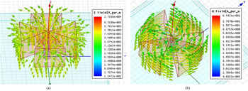
The simulation study of the near field distribution of the proposed TDRA has been carried out at resonant frequency 5.5 GHz using the Ansoft HFSS simulation software. The composite electric and magnetic field distributions of the proposed TDRA are shown in Fig. 7. It is apparent from Fig. 7 that the coaxial probe excites TM 10−1 dominant mode fields in the antenna elements. For TDRA the summation of indices of dominant mode should be zero, which is satisfying for TM 10−1 mode. Also it can be observed that the electric field component face their counter vectors and thus cause no radiation along the broadside direction. The resultant electric field is polarized along the z-direction and thus it leads to a vertically polarized radiation surrounding the radiating structure like a quarter wave electric monopole. Since the elements of the antenna composite TDRA structure effectively produces identical radiation fields at resonant frequency 5.5 GHz. The uniform and consistently symmetric monopole-type pattern has been achieved over the full matching bandwidth for the proposed antenna.
Near field distribution in proposed four elements TDRA (a) E-field, (b) H-field.

C) Far field distribution
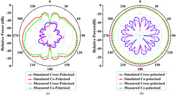
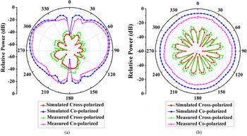
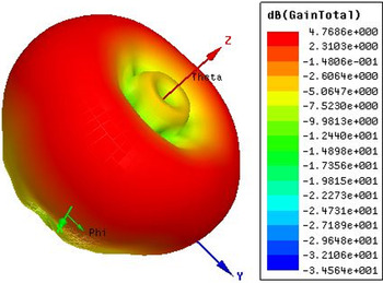
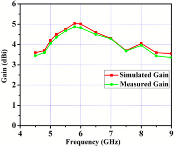
The far field patterns of the proposed antenna at resonant frequency and at 5.8 GHz are studied through Ansoft HFSS simulation software and also measured in anechoic chamber. The simulated and measured radiation pattern of the proposed antenna in E - and H-Plane at resonant frequency are shown in Figs 8(a) and 8(b) and at 5.8 GHz is shown in Figs 9(a) and 9(b), respectively. For the measurement and simulation E-plane has been chosen for ϕ = 0° and H-plane for θ = 90°. It is also apperant from the radiation pattern for both frequency that the co-polarization and cross-polarization level difference is more than 30 dB, which is appriciable for DRA. From Figs 8 and 9 it can be observed that the radiation pattern of the proposed antenna is omni-directional in H-plane. No radiation along broadside direction of the proposed DRA is in conformity with the counteracting E-field distributions within the elements of the proposed TDRA. Simulated radiation pattern are in good agreement with the measured radiation pattern. It is also observed that the simulated radiation efficiency and peak directivity of the proposed antenna is found 99% and 4.95 dBi, respectively. Three-dimensional (3D) radiation pattern of the proposed antenna is shown in Fig. 10. From Fig. 10, it is found that the peak gain of antenna is found 4.76 dBi. Figure 11 shows gain versus frequency curve, and from which it can be observed that the simulated and measured gain are in close agreement. For the antenna gain measurement, three antenna method has been used. The proposed antenna has been used as recevier antenna and 2–18 GHz horn antenna is used for transmission.
Radiation pattern of proposed four elements TDRA (a) in E-plane, (b) in H-plane at resonant frequency 5.45 GHz.

Radiation pattern of proposed four elements TDRA (a) in E-plane, (b) in H-plane at 5.8 GHz frequency.

3D radiation pattern of proposed four elements TDRA at resonant frequency.

Gain versus frequency curve of proposed four elements TDRA.

CONCLUSION
A wideband four element TDRA has been designed and fabricated. The simulation of the proposed antenna has been performed using Ansoft HFSS and CST Microwave Studio software. Measured results are in good agreement with simulated one. The proposed antenna has also been compared with single element TDRA and found enhancement in bandwidth. From the study it is inferred that the bandwidth of the proposed antenna has been found nearly 37% and provide a consistently symmetric monopole type of radiation pattern with 4.76 dBi peak gain at resonant frequency. The proposed antenna has been compared with other similar DRA shapes and found superior in performance. The designed antenna has wide application in 5.0 GHz WLAN (IEEE 802.16) and WiMAX band of communication.
ACKNOWLEDGEMENT
First author, Ravi Kumar Gangwar wishes to acknowledge to the TEQIP-II Project, Indian School of Mines, Dhanbad for awarding financial aid. Authors also would like to acknowledge Prof. Dharmendra Singh, Department of Electronics and Communication Engineering, IIT Roorkee, India, for his guidance and also for providing his antenna measurement facility at IIT Roorkee.
 Ravi Kumar Gangwar was born in Bareilly (Uttar Pradesh), India, in1983. He received his B.Tech. degree in Electronics and Communication Engineering from U.P. Technical University, Lucknow, India, in 2006, and Ph.D. degree in Electronics Engineering in 2011 from the Indian Institute of Technology (Banaras Hindu University), Varanasi, India. He is presently Assistant Professor in Department of Electronics Engineering, Indian School of Mines, Dhanbad. He served as Senior Research Fellow/Junior Research Fellow in the Department of Electronics Engineering, IIT-BHU during 2007–2011. He has authored or coauthored over 30 research papers in international/national journals/conference proceedings. His research interest includes dielectric resonator antenna, metamaterial, and bio-electromagnetics. He is a reviewer of PIER, International Journal of Electronics, International Journal of Microwave and Wireless Technology, Wireless Personnel Communication international journals.
 Pinku Ranjan was born in Nalanda (Bihar), India, in 1988. He received his B.Tech in Electronics and Communication Engineering from Jawaharlal Nehru Technological University (JNTU) Hyderabad, India, in 2010. He is presently pursuing his Ph.D. as Senior Research Fellow in Department of Electronics Engineering from Indian School of Mines Dhanbad, India. He served as Junior Research Fellow in the Department of Electronics Engineering, Indian School of Mines, Dhanbad, India, during 2012–2014. He has authored or co-authored for more than five research paper in international/national conference proceedings. His research interests include Dielectric Resonator Antenna and Bio- Electromagnetics.
 Abhishek Aigal obtained his Bachelor of Technology degree from Indian School of Mines, Dhanbad in Electronics and Communications Engineering, where he worked in the fields of Algorithms, Wireless Technology and Antenna. His current interests focus on Algorithms and Data Structures. He is currently employed at Ericsson.