Introduction
One of the main applications of nanofluidics is the possibility to build efficient filtration membranes. Reference Lee, Arnot and Mattia1–Reference Mattia, Lee and Calabrò4 After the first experiments Reference Holt, Park, Wang, Stadermann, Artyukhin, Grigoropoulos, Noy and Bakajin5–Reference Majumder, Chopra, Andrews and Hinds6 on fluid flow inside nanotubes, interest grew because channels with diameters of a few nanometers would mean the ability to filter by mechanical separation, starting from ultrafiltration (diameters of 10–100 nm), through nanofiltration (1–10 nm) up to reverse osmosis ranges (0.5–1 nm). Tubular carbon structures with an open central pore were the first nanotubes considered that have low-friction transport thanks to graphitic surfaces. We distinguish carbon nanotubes (CNTs) from carbon nanopipes (CNPs) produced by chemical vapor deposition (CVD) of amorphous carbon in alumina templates. Reference Whitby and Quirke7 More recently, boron nitride nanotubes (BNNTs) and silicon carbide nanotubes (SiCNTs) have also been used. Reference Ritos, Mattia, Calabrò and Reese8 The tubes are infiltrated in a dense material, referred to as the filling material, which can be a polymer or inorganic material. Ideally, the tubes are vertically aligned (VA) and the number of tubes is high. In this way, both tortuosity—defined as the ratio between the mean length of the flow path and the thickness of the membrane—and porosity, which depends strongly on the ratio between pore volume and filling material volume, are favorable. Reference Trivedi and Alameh2,Reference Mattia, Leese and Lee9 It is a great challenge to produce VA membranes with these features. We will discuss the modeling of liquid flow so that the effects of solid–liquid interactions, Reference Ritos, Mattia, Calabrò and Reese8,Reference Mattia and Calabrò10,Reference Calabrò, Lee and Mattia11 both with the tube wall and with the filling material, can be better understood.
Definitions and main assumptions
The first experimental evidence of high water flow in carbon nanotubes was obtained using vertically aligned carbon nanotube (VA-CNT) membranes. Reference Lee, Arnot and Mattia1–Reference Majumder, Chopra, Andrews and Hinds6 These were produced by infiltrating a nonpermeable matrix material into the gaps of a nanotube array grown by CVD on silicon wafers or similar substrates. Reference Majumder, Chopra and Hinds12–Reference Baek, Kim, Seo, Kim, Lee, Kim, Ahn, Bae, Lee, Lim, Lee and Yoon16 The filling material (a polymer or inorganic material) is dense and, therefore, the porosity of VA-CNT membranes consists solely of the inner channel of the nanotubes, allowing the construction of membranes capable of separating molecules based on the inner diameter of the nanotubes, which is controlled during the synthesis process. CNT membranes with sizes in the ultrafiltration, nanofiltration, and reverse osmosis range have all been produced. Reference Mattia, Leese and Lee9 The higher the density of the initial nanotube arrays, the higher the overall membrane permeability, provided the filling material can still be infiltrated around the tubes. Reference Yu, Funke, Falconer and Noble17
These experimental results have been accompanied by significant efforts in theoretical developments to explain the origin of the very high water flow observed. Reference Holt, Park, Wang, Stadermann, Artyukhin, Grigoropoulos, Noy and Bakajin5,Reference Majumder, Chopra, Andrews and Hinds6,Reference Majumder, Chopra and Hinds12 Nanoscale effects usually neglected in membrane modeling have been considered, in particular, slip. Reference Ruckenstein and Rajora18,Reference Blake19 However, the complexity of modeling a multitube membrane has meant that most work considered a simplified setting consisting of a single tube, potentially neglecting effects associated with a larger membrane, including surface roughness, and entry and end effects when flowing from the reserve to the pipes. Reference Sisan and Lichter20,Reference Walther, Ritos, Cruz-Chu, Megaridis and Koumoutsakos21
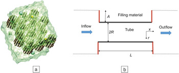
Figure 1 shows a schematic of typical three-dimensional and two-dimensional domains used for both theoretical and computational modeling. Figure 1a was obtained via molecular dynamics (MD) simulation, beginning with the known assumptions about the interactions between molecules. Reference Whitby and Quirke7,Reference Ritos, Mattia, Calabrò and Reese8, Reference Corry22,Reference Kannam, Todd, Hansen and Daivis23 The latter is primarily determined by the values of Lennard–Jones parameters used to model the van der Waals interactions between different liquids and the wall. There is a wide range of values in the literature, indicating differences in the results presented. Reference Werder, Walther, Jaffe, Halicioglu and Koumoutsakos24
(a) Computational 3D domain of a molecular dynamics simulation. Twelve nanotubes are vertically inserted in a membrane. Adapted with permission from Reference Reference Corry22. © 2008 American Chemical Society. (b) Schematic of the simplified 2D setting: a section of the membrane corresponding to the diameter of one tube connecting the inflow and outflow areas. The material boundaries, where the coupling between liquid and solid occurs, are shown by hard lines. The tube walls are shown in black, the filling material in red. Dotted lines represent fictitious boundaries where periodic conditions are imposed. In the x direction, L is the length of the tube; in our setting L >> R. The ratio between the length A and the tube radius R reflects the permeability of the membrane: low values of A/R give high permeability.

Continuous modeling of flow inside nanochannels starts with the Navier–Stokes equations for a Newtonian liquid. Next, considering pressure-driven flow inside a tube with a constant circular cross section, the classical assumptions—such as incompressibility, steady state, laminar flow, and constant viscosity inside the tube—lead to the Hagen–Poiseuille equation, Reference Mattia and Calabrò10,Reference Calabrò, Lee and Mattia11,Reference Mattia and Gogotsi25,Reference Köhler and Barros da Silva26 which gives a parabolic profile for the velocity of the liquid along the tube as a function of the distance from the tube’s axis. The only boundary condition that has to be fixed is the one at the tube’s wall. In the referenced Hagen–Poiseuille equation, the assumption made is that the liquid sticks to the wall, leading to the no-slip boundary condition. This is a good approximation at the macroscale, but it strongly contradicts the experimental evidence at the nanoscale. In fact, water has been observed flowing inside tubes whose diameter is not greater than 0.7 nm, which is twice the van der Waals diameter of a water molecule itself. Reference Holt, Park, Wang, Stadermann, Artyukhin, Grigoropoulos, Noy and Bakajin5,Reference Mi, Lin and Li15,Reference Mattia and Gogotsi25,Reference Thomas and McGaughey27 Liquid flow inside channels is measured in terms of flow rate, so that deviations from the no-slip predictions are quantified via the flow enhancement, which is the ratio between measured and no-slip flow.
To account for the observed enhanced flow, the no-slip boundary condition is replaced by the linear Navier condition that preserves the shear stress at the wall:
 $$- \lambda {{\partial u} \over {\partial r}}\left( {r = R} \right) = u\left( {r = R} \right).$$
In Equation 1, u(r) is the function that describes the velocity of the liquid along the tube as a function of the distance r from the tube axis to the tube wall fixed at distance r = R; λ is a parameter that has the dimension of length and is usually referred to as the slip length. The case of λ = 0 yields no-slip, whereas when λ increases, the flow profile flattens, approximating plug flow, and the velocity becomes constant across the tube’s diameter when assuming large slip lengths.
When the presence of slip is assumed, it follows naturally that this should take into account the properties of the coupling between the liquid and the material it is in contact with. High slip will then occur with solid/fluid combinations in which the adherence between the solid and the fluid is very low; Reference Tretheway and Meinhart28,Reference Choi, Westin and Breuer29 for water, such walls are called hydrophobic. Watanabe et al. Reference Watanabe, Udagawa and Udagawa30 showed evidence of slip at the walls for water flowing through a pipe when the pipe is made from a class of materials that they termed “water repellent.” On the other hand, small slip has been noticed in hydrophilic tubes. Reference Choi, Westin and Breuer29,Reference Lee, Leese and Mattia31
The next step is to define an expression for the slip length, from a model of the interactions between the fluid molecules close to the channel wall and the wall itself, under an external pressure gradient that makes the liquid flow. Tolstoi defined a region of reduced water viscosity near a hydrophobic wall, starting from statistical thermodynamics considerations, leading to a nonzero velocity at the wall that is linearly proportional to the applied pressure gradient ∆p. Reference Ruckenstein and Rajora18,Reference Blake19 Mattia and Calabrò have discussed how the proportionality constant can be expressed as the ratio D s/W A, where D s is the surface diffusion of the fluid molecules along the solid surface of the tube generated by the chemical potential arising from the pressure gradient, and W A is the work of adhesion, the solid–liquid interaction energy per unit surface. Reference Mattia and Calabrò10
Using this ratio in the Navier boundary condition (1) leads to the following velocity profile:
 $$u(r) = \left[ {{{{R^2} - {r^2}} \over L}{1 \over {4\mu }} + {{{D_S}} \over {{W_A}}}} \right]\Delta p,$$
where µ is the fluid viscosity and L is the tube length. The flow is obtained by integrating the velocity, and the flow enhancement is derived as:
 $$\varepsilon = 1 + 8\mu {L \over {{R^2}}}{{{D_s}} \over {{W_A}}}.$$
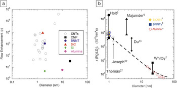
This enhancement, when compared with available data—both experimental and MD—showed good agreement, as can be seen in Figure 2 and References Reference Ritos, Mattia, Calabrò and Reese8, Reference Mattia and Calabrò10, and Reference Calabrò, Lee and Mattia11.
Flow enhancement measurements as reported in the literature. (a) The reported results are plotted on a log scale showing that no particular trend can be ascertained. (b) The same data are rescaled using Equation 3 and the model prediction is included—almost all of the data are in good agreement with model predictions. Note: CNT, carbon nanotubes; CNP, carbon nanopipe; BNNT, boron nitride nanotubes; SiCNT, silicon carbide nanotubes.

It should be noted that in more complex modeling, the coupling between liquid and solid also influences the properties of the bulk fluid, modifying, for example, its viscosity. Reference Calabrò, Lee and Mattia11,Reference Köhler and Barros da Silva26 Moreover, MD simulations have shown that imposing hydrophilic potentials or defects on a CNT structure can reduce the flow enhancement. Reference Joseph and Aluru32,Reference Nicholls, Borg, Lockerby and Reese33 Other MD simulations have also shown that functionalization of the CNT tips could be used to control selective permeation of ions through CNT membranes, Reference Corry3 which is important for their potential use in water filtration and desalination applications. Reference Mattia, Leese and Lee9 Experiments have shown that functionalization of the entrance to CNT membranes can significantly alter capillary filling and flow enhancement, Reference Majumder and Corry34 and that surface modification of the CNTs can be used to control their ability to imbibe liquids of a different nature. Reference Mattia, Bau and Gogotsi35,Reference Mattia, Rossi, Kim, Korneva, Bau and Gogotsi36 Finally, we point out that if an electrical potential is imposed on the membrane, this can affect the flow inside, leading to electro-osmotic flow. Reference Mattia, Leese and Calabrò37
In this article, we have focused on the macroscopic quantities that can influence the flow through VA nanotube membranes. In particular, we review the chemical and geometrical properties that influence flow enhancement.
The use of different materials
The overall performance of a VA nanotube membrane can be schematized as having two main contributions—the properties of the tubes and those of the material infiltrated between the nanotubes that determine the membrane’s surface. In both cases, geometric as well as chemical properties have to be considered.
For the tube, the geometric properties are related to the length and diameter, and the eventual presence of defects. Reference Tretheway and Meinhart28 The effect of diameter on flux is given by the quadratic dependence found in the Navier–Stokes equation; rejection in VA nanotube membranes mainly occurs via the size-exclusion mechanism, where the diameter determines which molecules are rejected. The length of the tube influences the flow enhancement, Reference Ritos, Mattia, Calabrò and Reese8,Reference Nicholls, Borg, Lockerby and Reese38 which is linearly proportional to the length, see Equation 3. Flow enhancement has been calculated via MD as a function of the tube aspect ratio for CNTs, BNNTs, and SiCNTs of comparable diameter (∼2 nm) demonstrating a linear dependence. Reference Ritos, Mattia, Calabrò and Reese8
For the infiltrated matrix material, the geometric properties are the intertube spacing and surface porosity, the ratio of the voids versus the dense area. The two quantities are related, therefore, changing the intertube spacing (i.e., the array density) for a nanotube of a certain size also modifies the porosity, and the overall permeability of the membrane is changed. Reference Mattia, Leese and Lee9 We should mention that the porosity and the tube length, which gives the thickness of the membrane, also influence the overall mechanical properties of the membrane such as resistance, and a compromise must be found for practical applications.
Finally, a geometric parameter that should also be considered is the orientation of the tubes. While always considered vertically aligned (i.e., perpendicular to the membrane’s surface), the orientation of tubes is, in practice, never perfect. This misalignment has several effects, first on the overall permeability, which can be quantified in terms of tortuosity and porosity. Regarding the latter, only when the tubes are vertically aligned is the porosity of the whole membrane equal to the surface porosity described earlier. When this is not the case, the membrane’s porosity, a quantity needed to compute the flow for modeling purposes, has to be obtained differently. It is well known that, at the macroscale, the orientation of a tube can create localized turbulence at the entrance and exit of a pore. While this has been qualitatively described at the nanoscale, Reference Sisan and Lichter20,Reference Sisavath, Jing, Pain and Zimmerman39–Reference Bedewy, Meshot, Guo, Verploegen, Lu and Hart44 no quantitative studies nor theoretical models have been published on this potentially important aspect.
The chemical properties of the internal tube wall and matrix material influence the fluid’s slip properties when the liquid flows in contact with these. As discussed in the previous section, slip properties can be expressed as a function of the ratio between surface diffusion, D s, and work of adhesion, W A. The lower the interaction energy between the liquid and the solid, the higher the surface diffusion leading to a larger slip. Conversely, the higher the value of W A, the stronger the adhesion between the solid and the liquid, leading to a small slip. It is worth noting that the work of adhesion accounts for variations in the surface chemistry and structure of the solid wall (e.g., chemical inhomogeneities or surface roughness). D s and W A are constant values for a specific solid–liquid couple and flow conditions. Both can be measured experimentally (e.g., W A can be measured via immersion calorimetry) or calculated via MD experiments. Reference Ritos, Mattia, Calabrò and Reese8 CNT water is the most extensively studied solid–liquid couple, both with experiments and MD. Limited experimental results are available for the flow of other polar and nonpolar liquids in CNTs, Reference Majumder, Chopra and Hinds12 while there is some modeling work on water flow in nanotubes of different materials, including boron nitride, Reference Ritos, Mattia, Calabrò and Reese8 silicon carbide, and silica. Reference Menon, Richter, Mavrandonakis, Froudakis and Andriotis45,Reference Malek and Sahimi46
D s and W A can change depending on fabrication of materials and the presence of defects. In particular, reducing the contact angle between liquid and solid increases W A, and known values for this parameter range from 97–350 mJm–2, respectively, for water on polytetrafluoroethylene and water on titania. Reference Ritos, Mattia, Calabrò and Reese8,Reference Mattia and Calabrò10
Challenges and open questions
We have described how modeling of fluid flow inside nanochannels requires knowledge of the interaction properties between the liquid and solid, and a description of the geometry. Nevertheless, the present state of the art is still far from a complete description of a system that is ready for industrial applications. The modeling is limited to one liquid flowing in a frozen configuration, while actual filtration applications have quite different features.
The first challenge on the modeling side concerns the possibility of using computational models to obtain additional information on solid–liquid interactions that cannot be obtained via direct experimental means. Another challenge is coupling MD simulations for parameter estimation and continuous models for complete simulations. The continuous model incorporated in computational fluid dynamics modules would allow the consideration of more complex and realistic situations. For example, if a mixture of liquids, rather than pure ones, could be modeled, computational simulations could help in understanding the dynamics of selectivity and rejection. Furthermore, well-known effects occurring on the feed side of a membrane, such as concentration polarization and fouling buildup, have not been investigated for nanotube membranes. As the liquid is filtered, the composition of the remaining feed and permeate (as well as the retentate in the case of cross-flow configurations) will change, altering the solid–liquid interactions at the surface of the membrane and inside the tubes. The ability to model these complex situations could lead to major innovations in, for example, the fabrication of membranes with different shapes or with multiple surface or matrix materials to respond to the different settings previously outlined.
The occurrence of fouling can also alter the geometry of the membrane, with corrosion (e.g., degradation of the polymer matrix due to chlorine) or formation of deposits on the membrane’s surface. Changes in geometry can also occur if the membrane deforms due to the applied pressure or, in the worst case, formation of cracks. All of these processes mainly consider the properties of the filling material, and self-cleaning processes and reinforcement materials are an active research area in membrane science. However, the presence of aligned (or nonaligned) nanotubes changes the mechanical, chemical, and electrical properties. Full comprehension of these phenomena is lacking.
Acknowledgment
The author gratefully acknowledges support from The Engineering and Physical Sciences Research Council Thought Project EP/M01486X/1 “From Membrane Material Synthesis to Fabrication and Function (SynFabFun).”

Francesco Calabrò is adjoint professor of applied mathematics and numerical analysis since 2009 in the Department of Electrical and Information Engineering at the University of Cassino and Southern Lazio, Italy. He received his BS degree in applied mathematics from the University of Naples Federico II, Italy, in 2001, his MS degree in applications of mathematics in industry and services at the University of Milano-Bicocca, Italy, and his PhD degree in computational science and informatics from the University of Naples Federico II in 2004. His research interests include isogeometric analysis and modeling in nanochannels and membranes. Calabrò can be reached by phone at +39 0776 2993621 or by email at calabro@unicas.it.