1 Introduction
Examples of millimetric objects bouncing on the surface of a bath as they cruise along the surface are common in capillary-scale applications; these include raindrop impacts (Zhbankova & Kolpakov Reference Zhbankova and Kolpakov1990; Ho et al. Reference Ho, Bliven, Wanninkhof and Schlosser1997) and locomotion of insects and small vertebrates (Bush & Hu Reference Bush and Hu2006). In the case of droplets, it was shown by Couder et al. (Reference Couder, Fort, Gautier and Boudaoud2005a ) that coalescence with an underlying bath of the same fluid can be inhibited through vertical oscillation of the bath. The droplet is prevented from merging with the bath by the sustenance of a thin air layer that separates the two at all times (Couder et al. Reference Couder, Fort, Gautier and Boudaoud2005a ; Terwagne, Vandewalle & Dorbolo Reference Terwagne, Vandewalle and Dorbolo2007). These droplets can bounce for extremely long times, displaying different bouncing regimes, which are controlled by the amplitude and frequency of the shaking. Moreover, within a certain range of parameters, these bouncing droplets can become unstable to horizontal perturbations (Couder et al. Reference Couder, Protière, Fort and Boudaoud2005b ), breaking the axial symmetry of the surface wave field. Droplets then bounce off a slanted free surface, acquiring a horizontal velocity component and thus start walking along a straight path.
Walking droplets are affected at each bounce by the wave field at the impact location. Since these waves were triggered by previous bounces, the droplet is in practice interacting with a record of its own trajectory. This droplet–wave association at millimetric scale has come to be known as a hydrodynamic pilot-wave (Bush Reference Bush2015). Hydrodynamic pilot-waves exhibit complex dynamics that have been shown to have numerous analogies with quantum-scale phenomena (Bush et al. Reference Bush, Couder, Gilet, Milewski and Nachbin2018), which motivated their study by several groups over the past 14 years. Some examples of models created to address walking droplet dynamics include a first phenomenological model by Eddi et al. (Reference Eddi, Sultan, Moukhtar, Fort, Rossi and Couder2011), a nonlinear spring-based surface–droplet interaction by Moláček & Bush (Reference Moláček and Bush2013b ), a stroboscopic model introduced by Oza, Rosales & Bush (Reference Oza, Rosales and Bush2013) and a model that introduced wave generation by impacts by Milewski et al. (Reference Milewski, Galeano-Rios, Nachbin and Bush2015).
Galeano-Rios, Milewski & Vanden-Broeck (Reference Galeano-Rios, Milewski and Vanden-Broeck2017) developed a model for the impact of a hydrophobic sphere onto the free surface of a bath. Their impact model modified the Wagner theory of surface impacts (Wagner Reference Wagner1932; Korobkin & Pukhnachov Reference Korobkin and Pukhnachov1988; Howison, Ockendon & Wilson Reference Howison, Ockendon and Wilson1991) to account for the reaction of the impacting solid to forces exerted by the flow, including capillary effects, and to intrinsically allow for a mechanism for the impacting solid to detach from the surface. This resulted in a model that can solve all stages of a rebounding impact at the capillary scale, provided the surface deformation is not too large. They essentially imposed a kinematic match between the motion of the free surface and that of the impacting sphere, i.e. they imposed the natural geometric and kinematic constraints, together with simple assumptions on the contact angle, to derive a solution strategy that yields predictions for the motion of the contact line and for the pressure field supported within the contact area. Their impact model was validated against experimental results and they went on to show that it can be used to accurately predict the vertical motion of bouncing droplets whilst also introducing fewer assumptions on the nature of the impact and, consequently, fewer parameters than in previous works (Moláček & Bush Reference Moláček and Bush2013a ; Milewski et al. Reference Milewski, Galeano-Rios, Nachbin and Bush2015).
Superposing translations of axisymmetric impacts on linear quasi-potential free-surface flows has proven to be a highly effective strategy to model walking droplets (Moláček & Bush Reference Moláček and Bush2013b
; Oza et al.
Reference Oza, Rosales and Bush2013; Milewski et al.
Reference Milewski, Galeano-Rios, Nachbin and Bush2015). This approximation is justified on the basis of some clear separation of scales: namely, the Faraday wavelength (
 $\unicode[STIX]{x1D706}_{F}\approx 0.5~\text{cm}$
) is long in relation to the droplet radius (
 $R_{o}\approx 0.4~\text{mm}$
); the droplet radius is in turn large in relation to the typical free-surface elevation (
 $\unicode[STIX]{x1D716}\lesssim 10~\unicode[STIX]{x03BC}\text{m}$
at impact location just before contact); and moreover the walking speed (
 $C_{w}\approx 1~\text{cm}~\text{s}^{-1}$
) is slow in relation to the phase velocity of the Faraday waves (
 $C_{p}\approx 20~\text{cm}~\text{s}^{-1}$
) and also to the typical vertical velocity of the impacting droplet (
 $U_{z}\approx 10~\text{cm}~\text{s}^{-1}$
). Under these assumptions, vertical forces can be calculated assuming the impact is normal to a flat horizontal surface. The horizontal component of the impact forces on the droplet can then be computed assuming these impact forces are actually normal to the relatively small local average of the surface gradient in the region of impact.
The kinematic match method is very versatile, and is applicable to impact problems with no assumptions on symmetry; however, its implementation in such a general case is more complex. In this paper, we demonstrate that, under the assumptions above, we may approximate the dynamics by a superposition of translated axisymmetric impacts. Using the kinematic match for these axisymmetric impacts results in a more detailed and realistic modelling of the walking droplets, in relation to existing methods, whilst also providing information about the fastest time scales in the problem, such as those of the evolution of forces and of the pressed area during impacts.
In this work, we also demonstrate how to combine an efficient solution of the large-scale non-axisymmetric free-surface waves using a spectral method developed in Milewski et al. (Reference Milewski, Galeano-Rios, Nachbin and Bush2015) with the superposition of axisymmetric impacts described above, so as to obtain an accurate and efficient model for walking droplets that is free of any impact parametrisation. The decomposition introduced here opens many new possibilities, as there are no restricting assumptions on the geometry of the bath, or the presence of neighbouring droplets. This is fundamental to simulate collective behaviour of bouncing and walking droplets, as keeping the details of wave generation by impact has proven to be essential to capture wave-mediated droplet–droplet interactions (Galeano-Rios et al. Reference Galeano-Rios, Couchman, Caldairou and Bush2018).
In § 2 we pose the full problem, presenting the kinematic match method, expanding the discussion in Galeano-Rios et al. (Reference Galeano-Rios, Milewski and Vanden-Broeck2017), and reviewing the linearised quasi-potential fluid model. We close this section by justifying the superposition of translations of axisymmetric impacts to obtain a model for walking droplets and deriving a model for friction effects during droplet–surface contacts that is consistent with the theory developed here and that incorporates changes in pressed area over droplet–surface contacts. In § 3 we summarise the resulting mathematical problems, and describe the numerical methods used to solve each and the recombination of their results. We also show how we use experimental data to set our single parameter for skidding friction during droplet contacts. In § 4 we present comparisons to experimental data available in the literature, including bouncing modes, impact and take-off phases and wave field topography, and we show that our model is able to capture the newly discovered walking droplet phenomenon of superwalkers (Valani, Slim & Simula Reference Valani, Slim and Simula2019). In the case of superwalkers, we are specifically able to capture the transition from bouncing to walking as the second frequency is introduced, and to obtain wave fields that qualitatively resemble that of superwalkers. We highlight that we were unable to obtain realistic results with the model introduced by Milewski et al. (Reference Milewski, Galeano-Rios, Nachbin and Bush2015). Finally, in § 5 we discuss our findings and consider future directions.
2 Problem formulation
We consider the three-dimensional, free-surface, incompressible flow of a fluid bath of infinite depth and uniform density
 $\unicode[STIX]{x1D70C}$
. The fluid flow is subject to gravitational, viscous and interfacial forces. We introduce Cartesian coordinates with gravity pointing in the negative
 $z$
direction. We also assume that the free surface can be described by
 $z=\unicode[STIX]{x1D702}(\boldsymbol{x},t)$
, where
 $\boldsymbol{x}=(x,y)$
, whose spatial domain is the entire plane. We define
 $\boldsymbol{u}$
and
 $p$
as the velocity and pressure fields, respectively,
 $\unicode[STIX]{x1D708}$
as the kinematic viscosity of the fluid and
 $\boldsymbol{g}=(0,0,-G)$
as the acceleration due to gravity. We note that
 $G$
can be a function of time. Under these assumptions, the flow is governed by
 $$\begin{eqnarray}\displaystyle & & \displaystyle \boldsymbol{u}_{t}+\boldsymbol{u}\boldsymbol{\cdot }\unicode[STIX]{x1D735}\boldsymbol{u}=\unicode[STIX]{x1D735}\left(-{\displaystyle \frac{p}{\unicode[STIX]{x1D70C}}}\right)+\unicode[STIX]{x1D708}\unicode[STIX]{x0394}\boldsymbol{u}+\boldsymbol{g},\quad z\leqslant \unicode[STIX]{x1D702}(\boldsymbol{x},t),\end{eqnarray}$$
 $$\begin{eqnarray}\displaystyle & & \displaystyle \unicode[STIX]{x1D735}\boldsymbol{\cdot }\boldsymbol{u}=0,\quad z\leqslant \unicode[STIX]{x1D702}(\boldsymbol{x},t).\end{eqnarray}$$
The velocity field
 $\boldsymbol{u}$
is subject to decay conditions at infinity,
 $$\begin{eqnarray}\displaystyle \boldsymbol{u}\rightarrow 0,\quad \text{as }\sqrt{x^{2}+y^{2}+z^{2}}\rightarrow \infty , & & \displaystyle\end{eqnarray}$$
and the free surface is subject to the kinematic boundary condition,
 $$\begin{eqnarray}\displaystyle \unicode[STIX]{x1D702}_{t}+\boldsymbol{u}\boldsymbol{\cdot }\unicode[STIX]{x1D735}(\unicode[STIX]{x1D702}-z)=0,\quad z=\unicode[STIX]{x1D702}(\boldsymbol{x},t), & & \displaystyle\end{eqnarray}$$
and the dynamic boundary condition,
 $$\begin{eqnarray}\displaystyle -p\hat{\boldsymbol{n}}+\unicode[STIX]{x1D64F}\boldsymbol{\cdot }\hat{\boldsymbol{n}}=(\unicode[STIX]{x1D70E}\unicode[STIX]{x1D705}[\unicode[STIX]{x1D702}]-p_{s}(\boldsymbol{x},t))\hat{\boldsymbol{n}},\quad z=\unicode[STIX]{x1D702}(\boldsymbol{x},t). & & \displaystyle\end{eqnarray}$$
Here
 $\hat{\boldsymbol{n}}$
is the unitary vector normal to the free surface, pointing out of the fluid domain;
 $\unicode[STIX]{x1D64F}$
is the deviatoric part of the stress tensor;
 $p_{s}$
is the pressure above the free surface;
 $\unicode[STIX]{x1D70E}$
is the surface tension coefficient; and
 $\unicode[STIX]{x1D705}[\cdot ]$
is twice the mean curvature operator, with the convention of positive curvature for convex functions, i.e.
 $$\begin{eqnarray}\displaystyle \unicode[STIX]{x1D705}[\unicode[STIX]{x1D702}]={\displaystyle \frac{(1+\unicode[STIX]{x1D702}_{y}^{2})\unicode[STIX]{x1D702}_{xx}-2\unicode[STIX]{x1D702}_{x}\unicode[STIX]{x1D702}_{y}\unicode[STIX]{x1D702}_{xy}+(1+\unicode[STIX]{x1D702}_{x}^{2})\unicode[STIX]{x1D702}_{yy}}{(1+\unicode[STIX]{x1D702}_{x}^{2}+\unicode[STIX]{x1D702}_{y}^{2})^{3/2}}}. & & \displaystyle\end{eqnarray}$$
We define
 $h(t)$
as the height of the lowest point, the ‘south pole’, of the impacting sphere,
 $c_{f}$
as the coefficient of friction due to air drag on the sphere,
 $m_{s}$
as the mass of the impacting object, and we consider
 $p_{s}(\boldsymbol{x},t)=0$
everywhere outside the area that is pressed by the impacting solid. In the pressed area
 $A(t)$
, we disregard the thickness of the air layer separating the surface of the bath and the sphere, i.e.
 $A(t)\in \mathbb{R}^{2}$
is the projection onto the
 $xy$
plane of the set
 $S(t)$
, which is given by the part of the surface of the impacting object that coincides with the free surface of the bath. Consequently, we have
 $$\begin{eqnarray}\displaystyle h_{tt}=-G-{\displaystyle \frac{c_{f}}{m_{s}}}\,h_{t}+{\displaystyle \frac{1}{m_{s}}}\int _{A(t)}p_{s}\,\text{d}A. & & \displaystyle\end{eqnarray}$$
We denote by
 $z_{s}(\boldsymbol{x})$
the height of the lower half of the sphere, such that
 $z_{s}(\boldsymbol{X})=0$
, with
 $\boldsymbol{X}=(X,Y)$
being the horizontal coordinates of the south pole of the sphere. On the contact line
 $L(t)$
, i.e. the boundary of
 $A(t)$
, we define
 $\unicode[STIX]{x2202}_{n}$
as the derivative in the direction normal to
 $L(t)$
which points outside of the plane region
 $A(t)$
. We impose continuity of the free-surface gradient on
 $L(t)$
, as would be expected in the presence of an intervening air layer. Solutions must therefore satisfy
 $$\begin{eqnarray}\displaystyle & \displaystyle p_{s}(\boldsymbol{x},t)=0,\quad \boldsymbol{x}\notin A(t), & \displaystyle\end{eqnarray}$$
 $$\begin{eqnarray}\displaystyle & \displaystyle \unicode[STIX]{x1D702}(\boldsymbol{x},t)=h(t)+z_{s}(\boldsymbol{x}),\quad \boldsymbol{x}\in A(t), & \displaystyle\end{eqnarray}$$
 $$\begin{eqnarray}\displaystyle & \displaystyle \unicode[STIX]{x1D702}(\boldsymbol{x},t)<h(t)+z_{s}(\boldsymbol{x}),\quad \boldsymbol{x}\notin A(t), & \displaystyle\end{eqnarray}$$
 $$\begin{eqnarray}\displaystyle & \displaystyle \unicode[STIX]{x2202}_{n}\unicode[STIX]{x1D702}(\boldsymbol{x},t)=\unicode[STIX]{x2202}_{n}z_{s}(\boldsymbol{x}),\quad \boldsymbol{x}\in L(t), & \displaystyle\end{eqnarray}$$
where we define
 $z_{s}(\boldsymbol{x})=\infty$
away from the sphere. We emphasise that (2.8)–(2.11) simply state the minimal compatibility conditions consistent with a model that ignores the effects of the air flow in the lubrication layer. We also note that (2.11) corresponds to our assumption of perfect hydrophobicity. This assumption is based on the established fact that there is an intervening air layer separating droplet and bath (Couder et al.
Reference Couder, Fort, Gautier and Boudaoud2005a
), and therefore no contact angle smaller than
 $\unicode[STIX]{x03C0}$
is to be expected. It is worth mentioning that it is possible to modify this condition to allow for different, or even dynamic, contact angles.
We highlight that determining
 $A(t)$
is itself a part of the problem; that is to say, finding the pressure field and its domain is a two-dimensional free-boundary problem within our original three-dimensional free-boundary fluid-flow problem. Moreover, the problem of the pressure field is a free-boundary problem with an added difficulty, given that the domain of the pressure actually collapses to a point upon lift-off and reappears from a point when a new impact takes place.
2.1 Solving the two free-boundary problems
The algorithm presented in Galeano-Rios et al. (Reference Galeano-Rios, Milewski and Vanden-Broeck2017) solves the problem of the suddenly appearing pressed area and its subsequent evolution upon the impact of a solid. Moreover, the method is able to deal with the vanishing contact area when lift-off takes place. We review it in what follows. We first consider, for simplicity, the solid to be fixed as the free surface impacts on it. That is to say, we consider the case of
 $h(t)$
being constant and solving the system given by (2.1)–(2.11), disregarding (2.7) initially. We then discuss how (2.7) is introduced.
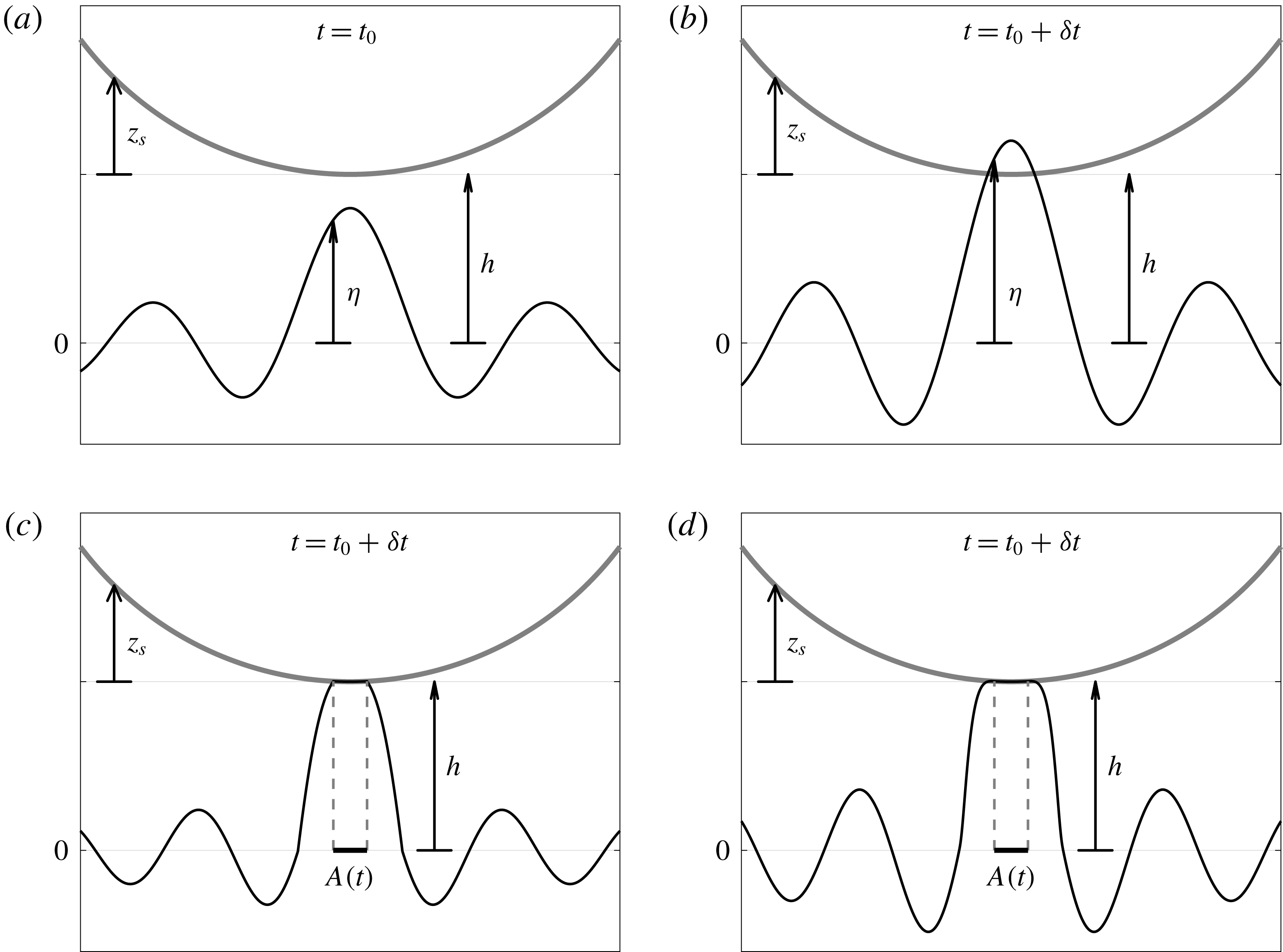
Schematics of onset of contact as solved by the kinematic match method. The boundary of the fixed solid, given by
 $z_{s}$
, is shown in grey; and the fluid interface, given by
 $\unicode[STIX]{x1D702}$
, in black. The height of the solid surface
 $z_{s}$
is measured with respect to that of its lowest point
 $h$
. Panels show: (a) regular evolution with no pressed area, (b) inconsistent estimate of free surface at
 $t=t_{0}+\unicode[STIX]{x1D6FF}t$
, (c) tentative solution for
 $t=t_{0}+\unicode[STIX]{x1D6FF}t$
with an
 $A_{test}$
that yields a wrong contact angle, and (d) solution with an
 $A_{test}$
that yields the right contact angle.

We consider the free surface of a fluid bath which, at a time
 $t=t_{0}$
, approaches a fixed, perfectly hydrophobic solid, shown in figure 1(a). In order to calculate the free-surface elevation at a certain time
 $t_{0}+\unicode[STIX]{x1D6FF}t$
, we need to solve the free-boundary problem over the time interval
 $t\in [t_{0},t_{0}+\unicode[STIX]{x1D6FF}t]$
. First, we tentatively impose
 $p_{s}(\boldsymbol{x},t)=0$
and we solve the system given by (2.1)–(2.6); if the solution satisfies (2.10) everywhere (i.e. predicts no contact or overlap between the fluid and the solid), then it trivially solves the remaining conditions of system (2.1)–(2.11). However, if (as in the example of figure 1) our prediction for the location of the free surface at time
 $t_{0}+\unicode[STIX]{x1D6FF}t$
suggests that part of the fluid occupies the same space as the solid, then we have not obtained a solution to (2.1)–(2.11) and an impact must have occurred; see figure 1(b). The evolution of the free surface should have been constrained by the presence of the solid and there should be a region within which
 $p_{s}(\boldsymbol{x},t)$
was not identically zero over the interval
 $[t_{0},t_{0}+\unicode[STIX]{x1D6FF}t]$
.
In order to find a correct solution to system (2.1)–(2.11), and since
 $A(t_{0}+\unicode[STIX]{x1D6FF}t)$
is to be determined, we proceed by testing a contact area candidate
 $A_{test}$
. We assume the contact area changes continuously; therefore
 $A_{test}$
must be small at the onset of contact. We solve the system for
 $\unicode[STIX]{x1D702}$
everywhere outside
 $A_{test}$
, and for the value of
 $p_{s}$
on
 $A_{test}$
(where
 $\unicode[STIX]{x1D702}$
is known). The method exchanges the known and unknown variables in the pressed area, yielding a closed problem for system (2.1)–(2.9) at
 $t_{0}+\unicode[STIX]{x1D6FF}t$
. Naturally, the solution to (2.1)–(2.9), obtained assuming
 $A(t+\unicode[STIX]{x1D6FF}t)=A_{test}$
, might not satisfy (2.10) or (2.11), since this was just an initial choice, so we need to verify these. If either condition is not satisfied, we repeat the process using a new
 $A_{test}$
, obtained by perturbing our prior choice until the solution satisfies (2.10) and (2.11) (see figures 1(c) and 1(d)).
At a time
 $t=t_{1}$
, when the fluid is in contact with the solid (i.e.
 $A(t_{1})\neq \emptyset$
), we proceed with the method in a similar manner. For time
 $t_{1}+\unicode[STIX]{x1D6FF}t$
we iterate on our candidate pressed areas
 $A_{test}$
, chosen in the vicinity of
 $A(t_{1})$
, and we solve system (2.1)–(2.9) for each
 $A_{test}$
until we verify (2.10) and (2.11). We note that, if
 $A(t_{1})$
is relatively small, the empty set is considered to be in its vicinity and therefore we include the possibility of
 $A_{test}=\emptyset$
, i.e.
 $p_{s}(\boldsymbol{x},t)=0$
.
When the impacting object is able to move vertically, the problem involves the response of the fluid forces onto it and we still need to iterate on the contact area; however, we no longer know a priori the exact elevation of the free surface
 $\unicode[STIX]{x1D702}$
on
 $A_{test}$
. Nevertheless, we know
 $\unicode[STIX]{x1D702}$
up to a vertical translation, given by
 $h(t)$
. This vertical translation adds an unknown to the system, but we also add (2.7), which closes the problem (2.1)–(2.9) for a given
 $A_{test}$
at
 $t=t_{0}+\unicode[STIX]{x1D6FF}t$
. We can thus iterate on
 $A_{test}$
once again, and stop the iteration when (2.10) and (2.11) are satisfied.
2.2 The linearised model
2.2.1 Linearised fluid equations
Following Galeano-Rios et al. (Reference Galeano-Rios, Milewski and Vanden-Broeck2017) we use a linearised quasi-potential approximation of the fluid flow, with
 $\boldsymbol{u}$
defined on the domain
 $D=\{(\boldsymbol{x},z),z\leqslant 0\}$
, where
 $z=0$
is the undisturbed free-surface level. We define
 $\unicode[STIX]{x1D711}(\boldsymbol{x},z,t)$
as the velocity potential,
 $\unicode[STIX]{x1D6E5}_{H}$
as the two-dimensional Laplacian, i.e.
 $\unicode[STIX]{x1D6E5}_{H}=\unicode[STIX]{x2202}_{xx}+\unicode[STIX]{x2202}_{yy}$
, and
 $N$
as the Dirichlet-to-Neumann operator, given by
 $$\begin{eqnarray}\displaystyle N\unicode[STIX]{x1D711}(\boldsymbol{x},0,t)=\unicode[STIX]{x1D711}_{z}(\boldsymbol{x},0,t). & & \displaystyle\end{eqnarray}$$
In formulating the Faraday wave problem, we set
 $g$
as the gravity constant,
 $a$
as the amplitude of the vertical shaking and
 $\unicode[STIX]{x1D714}_{o}$
as its angular frequency. The fluid viscosity
 $\unicode[STIX]{x1D708}$
is corrected to
 $\unicode[STIX]{x1D708}^{\ast }$
in order to use a quasi-potential approximation whilst still matching the driving amplitude at which the Faraday threshold is observed. For the parameter regime at which we run simulations (see appendix A),
 $\unicode[STIX]{x1D708}^{\ast }=0.8025\unicode[STIX]{x1D708}$
(Milewski et al.
Reference Milewski, Galeano-Rios, Nachbin and Bush2015). We adopt the Faraday wavelength
 $\unicode[STIX]{x1D706}_{F}$
as the unit length, the reciprocal of the subharmonic Faraday wave frequency
 $f_{F}^{-1}$
as the unit time, and
 $\unicode[STIX]{x1D70C}\unicode[STIX]{x1D706}_{F}^{3}$
as the unit mass, where
 $\unicode[STIX]{x1D70C}$
is the density of the bath’s fluid. We also define
 $$\begin{eqnarray}\displaystyle Fr=\unicode[STIX]{x1D706}_{F}\,f_{F}^{2}/g,\quad We=\unicode[STIX]{x1D70C}\unicode[STIX]{x1D706}_{F}^{3}\,f_{F}^{2}/\unicode[STIX]{x1D70E},\quad \unicode[STIX]{x1D6E4}=a\unicode[STIX]{x1D714}_{o}^{2}/g,\quad Re=\unicode[STIX]{x1D706}_{F}^{2}\,f_{F}/\unicode[STIX]{x1D708}^{\ast }, & & \displaystyle\end{eqnarray}$$
and
 $\unicode[STIX]{x1D719}(\boldsymbol{x},t)=\unicode[STIX]{x1D711}(\boldsymbol{x},0,t)$
.
The free surface can be shown to evolve (Galeano-Rios et al. Reference Galeano-Rios, Milewski and Vanden-Broeck2017) according to
 $$\begin{eqnarray}\displaystyle & \displaystyle \unicode[STIX]{x1D702}_{t}={\displaystyle \frac{2}{Re}}\unicode[STIX]{x1D6E5}_{H}\unicode[STIX]{x1D702}+N\unicode[STIX]{x1D719}, & \displaystyle\end{eqnarray}$$
 $$\begin{eqnarray}\displaystyle & \displaystyle \unicode[STIX]{x1D719}_{t}=-{\displaystyle \frac{(1-\unicode[STIX]{x1D6E4}\cos (4\unicode[STIX]{x03C0}t))}{Fr}}\unicode[STIX]{x1D702}+{\displaystyle \frac{1}{We}}\unicode[STIX]{x1D705}[\unicode[STIX]{x1D702}]+{\displaystyle \frac{2}{Re}}\unicode[STIX]{x1D6E5}_{H}\unicode[STIX]{x1D719}-p_{s}, & \displaystyle\end{eqnarray}$$
subject to
 $$\begin{eqnarray}\displaystyle & \displaystyle \unicode[STIX]{x1D702}\rightarrow 0,\quad \text{when }\sqrt{x^{2}+y^{2}}\rightarrow \infty , & \displaystyle\end{eqnarray}$$
 $$\begin{eqnarray}\displaystyle & \displaystyle \unicode[STIX]{x1D719}\rightarrow 0,\quad \text{when }\sqrt{x^{2}+z^{2}}\rightarrow \infty . & \displaystyle\end{eqnarray}$$
We note that these equations describe the free surface in the frame of reference of the moving bath, which introduces a time-dependent coefficient in (2.15), and that the curvature
 $\unicode[STIX]{x1D705}$
is not yet linearised. In fact, we will retain the full curvature in the contact area, where it is
 $O(1)$
and known a priori from the geometry of the solid, as was done in Galeano-Rios et al. (Reference Galeano-Rios, Milewski and Vanden-Broeck2017).
2.2.2 Vertical dynamics of the sphere
We recall that
 $m_{s}$
is the mass of the droplet and define
 $\unicode[STIX]{x1D707}_{air}$
as the dynamic viscosity of air,
 $R_{o}$
as the droplet radius and
 $h^{c}$
as the height of the centre of mass, which yields
 $h=(h^{c}-R_{o})/\unicode[STIX]{x1D706}_{F}$
as the dimensionless height of the south pole of the sphere. We approximate the effects of air on the moving droplet using Stokes’ drag and we introduce the dimensionless quantities
 $$\begin{eqnarray}\displaystyle Ma=m_{s}/(\unicode[STIX]{x1D70C}\unicode[STIX]{x1D706}_{F}^{3}),\quad So=6\unicode[STIX]{x03C0}\unicode[STIX]{x1D707}_{air}R_{o}/(m_{s}\,f_{F}). & & \displaystyle\end{eqnarray}$$
We thus have
 $$\begin{eqnarray}\displaystyle h_{tt}=-{\displaystyle \frac{(1-\unicode[STIX]{x1D6E4}\cos (4\unicode[STIX]{x03C0}t))}{Fr}}-So\,h_{t}+{\displaystyle \frac{1}{Ma}}\int _{A(t)}p_{s}\,\text{d}A. & & \displaystyle\end{eqnarray}$$
We describe the lower half of the impacting sphere, in dimensionless variables, using
 $$\begin{eqnarray}\displaystyle z_{s}(\boldsymbol{x})=\left\{\begin{array}{@{}ll@{}}{\displaystyle \frac{R_{o}}{\unicode[STIX]{x1D706}_{F}}}-\sqrt{{\displaystyle \frac{R_{o}^{2}}{\unicode[STIX]{x1D706}_{F}^{2}}}-|\boldsymbol{x}|^{2}}, & |\boldsymbol{x}|\leqslant {\displaystyle \frac{R_{o}}{\unicode[STIX]{x1D706}_{F}}},\\[6.0pt] \infty , & |\boldsymbol{x}|>{\displaystyle \frac{R_{o}}{\unicode[STIX]{x1D706}_{F}}}.\end{array}\right. & & \displaystyle\end{eqnarray}$$
Thus, given the horizontal location of the centre of mass as
 $\boldsymbol{X}(t)=(X(t),Y(t))$
, we can rewrite constraints (2.8)–(2.11) as
 $$\begin{eqnarray}\displaystyle & \displaystyle p_{s}=0,\quad \boldsymbol{x}\notin A(t), & \displaystyle\end{eqnarray}$$
 $$\begin{eqnarray}\displaystyle & \displaystyle \unicode[STIX]{x1D702}(\boldsymbol{x},t)=h(t)+z_{s}(\boldsymbol{x}-\boldsymbol{X}(t)),\quad \boldsymbol{x}\in A(t), & \displaystyle\end{eqnarray}$$
 $$\begin{eqnarray}\displaystyle & \displaystyle \unicode[STIX]{x1D702}(\boldsymbol{x},t)<h(t)+z_{s}(\boldsymbol{x}-\boldsymbol{X}(t)),\quad \boldsymbol{x}\notin A(t), & \displaystyle\end{eqnarray}$$
 $$\begin{eqnarray}\displaystyle & \displaystyle \unicode[STIX]{x2202}_{n}\unicode[STIX]{x1D702}(\boldsymbol{x},t)=\unicode[STIX]{x2202}_{n}z_{s}(\boldsymbol{x}-\boldsymbol{X}(t)),\quad \boldsymbol{x}\in L(t). & \displaystyle\end{eqnarray}$$
The horizontal trajectory
 $\boldsymbol{X}(t)$
is naturally dependent on the surface waves, and it needs to be coupled to system (2.14)–(2.24) to close the problem. For the sake of clarity, we present the horizontal dynamics in detail later in the text.
We highlight that, whilst the problem given by (2.14)–(2.24) is linear during each droplet flight, the problem remains highly nonlinear during impacts. The implicit nonlinearity takes place through the free-boundary problem for the pressure and the pressed area.
2.3 Approximation by superposition of normal impacts
We now introduce a further approximation to the problem, namely we consider impacts to be quasi-normal to the surface. This approximation was used by all previous works on walking droplets; however, the arguments that follow constitute (to the best of our knowledge) the first mathematical justification for it.
As mentioned in § 1, the walking velocity of droplets (
 $C_{w}\approx 1~\text{cm}~\text{s}^{-1}$
) is typically small relative to the vertical velocity of impact (
 $U_{z}\approx 10~\text{cm}~\text{s}^{-1}$
). This means that impacts are nearly vertical and that the difference between imposing condition (2.22) exactly and approximately (i.e. using the simplification that
 $\boldsymbol{X}(t)$
is constant during the impact) is of the order of the distance that the droplet moved during contact with the bath multiplied by the gradient of
 $z_{s}$
(bottom half of a sphere). Moreover, the linear approximation to surface deflection allows for the problem to be decomposed into a vertical (i.e. almost normal) impact on an initially quiescent interface and the unforced evolution of the waves.
We consider the time
 $t=t_{0}$
at which impact is imminent and we rewrite equation (2.22), in dimensionless units, as for
 $t\in (t_{0},t_{l})$
:
 $$\begin{eqnarray}\displaystyle \unicode[STIX]{x1D702}(\boldsymbol{x},t)=h(t)+z_{s}(\boldsymbol{x}-\boldsymbol{X}(t_{0}))+[z_{s}(\boldsymbol{x}-\boldsymbol{X}(t))-z_{s}(\boldsymbol{x}-\boldsymbol{X}(t_{0}))],\quad \boldsymbol{x}\in A(t). & & \displaystyle\end{eqnarray}$$
Here we know the term in square brackets to be of
 $O(|\unicode[STIX]{x1D735}z_{s}|C_{w}(t_{l}-t_{0})/\unicode[STIX]{x1D706}_{F})$
, where
 $t_{l}$
is the time at which lift-off happens with
 $t_{l}-t_{0}<T_{F}/2$
(typically), and
 $C_{w}$
is the typical speed of a walking droplet, which is small with respect to the phase velocity of the waves,
 $C_{p}=\unicode[STIX]{x1D706}_{F}/T_{F}$
. Moreover, for the case of an impacting sphere, when the radius of
 $A(t)$
is less than half the radius of the sphere (as is the typical case for walking droplets),
 $|\unicode[STIX]{x1D735}z_{s}|$
is at most
 $O(1)$
. Therefore, the term in square brackets is at most
 $O(C_{w}/C_{p})$
(typically
 $C_{w}/C_{p}\approx 0.05$
) and thus we can conclude that, near the impact location, we can impose an axisymmetric kinematic condition (by ignoring the term in square brackets) with an error of at most this order.
We now rewrite the quasi-normal impact as the superposition of three different problems: problem
 $a$
, given by the axisymmetric impact of a sphere onto the quiescent surface of a bath; problem
 $b$
, defined by the unforced wave field evolution of the free surface without the ongoing impact; and problem
 $r$
, given by the remaining terms in the full problem. More specifically, we define problems
 $a$
and
 $b$
, such that
 $$\begin{eqnarray}\displaystyle & \displaystyle \unicode[STIX]{x1D702}=\unicode[STIX]{x1D702}^{a}+\unicode[STIX]{x1D702}^{b}+\unicode[STIX]{x1D702}^{r}, & \displaystyle\end{eqnarray}$$
 $$\begin{eqnarray}\displaystyle & \displaystyle \unicode[STIX]{x1D719}=\unicode[STIX]{x1D719}^{a}+\unicode[STIX]{x1D719}^{b}+\unicode[STIX]{x1D719}^{r}, & \displaystyle\end{eqnarray}$$
 $$\begin{eqnarray}\displaystyle & \displaystyle h(t)=h^{a}(t)+\unicode[STIX]{x1D702}^{b}(\boldsymbol{X}(t),t)+h^{r}(t), & \displaystyle\end{eqnarray}$$
where the super-indices
 $a$
and
 $b$
indicate the solution of each problem and
 $r$
is the remainder with respect to the solution of the full impact problem (2.14)–(2.24). First, for
 $t\in [t_{0},t_{l}]$
, we define the homogeneous problem
 $b$
as
 $$\begin{eqnarray}\displaystyle & \displaystyle \unicode[STIX]{x1D702}_{t}^{b}={\displaystyle \frac{2}{Re}}\unicode[STIX]{x1D6E5}_{H}\unicode[STIX]{x1D702}^{b}+N\unicode[STIX]{x1D719}^{b}, & \displaystyle\end{eqnarray}$$
 $$\begin{eqnarray}\displaystyle & \displaystyle \unicode[STIX]{x1D719}_{t}^{b}=-{\displaystyle \frac{(1-\unicode[STIX]{x1D6E4}\cos (4\unicode[STIX]{x03C0}t))}{Fr}}\unicode[STIX]{x1D702}^{b}+{\displaystyle \frac{1}{We}}\unicode[STIX]{x1D6E5}_{H}\unicode[STIX]{x1D702}^{b}+{\displaystyle \frac{2}{Re}}\unicode[STIX]{x1D6E5}_{H}\unicode[STIX]{x1D719}^{b}, & \displaystyle\end{eqnarray}$$
subject to
 $\unicode[STIX]{x1D702}^{b}$
,
 $\unicode[STIX]{x1D719}^{b}\rightarrow 0$
when
 $|x|\rightarrow \infty$
, with
 $$\begin{eqnarray}\displaystyle \unicode[STIX]{x1D702}^{b}(\boldsymbol{x},t_{0})=\unicode[STIX]{x1D702}(\boldsymbol{x},t_{0})\quad \text{and}\quad \unicode[STIX]{x1D719}^{b}(\boldsymbol{x},t_{0})=\unicode[STIX]{x1D719}(\boldsymbol{x},t_{0}). & & \displaystyle\end{eqnarray}$$
That is to say, problem
 $b$
gives the evolution of the fluid flow as if the impact that occurs in the time interval
 $[t_{0},t_{l}]$
does not take place. We highlight that, due to the finite wave speed, outside the vicinity of the impact location, problem
 $b$
is in fact the full problem.
We can then rewrite equation (2.25) using equation (2.26) and subtract
 $\unicode[STIX]{x1D702}^{b}(\boldsymbol{X}(t),t)$
from both sides to obtain
 $$\begin{eqnarray}\displaystyle & & \displaystyle \unicode[STIX]{x1D702}^{a}(\boldsymbol{x},t)+[\unicode[STIX]{x1D702}^{b}(\boldsymbol{x},t)-\unicode[STIX]{x1D702}^{b}(\boldsymbol{X}(t),t)]+\unicode[STIX]{x1D702}^{r}(\boldsymbol{x},t)\nonumber\\ \displaystyle & & \displaystyle \quad =[h(t)-\unicode[STIX]{x1D702}^{b}(\boldsymbol{X}(t),t)]+z_{s}(\boldsymbol{x}-\boldsymbol{X}(t_{0}))+O(C_{w}/C_{p}),\end{eqnarray}$$
where the term in square brackets on the right-hand side of (2.32) will be used to define
 $h^{a}$
as used in (2.28). Namely, for
 $t\in [t_{0},t_{l}]$
, we define the axisymmetric impact problem
 $a$
as
 $$\begin{eqnarray}\displaystyle & \displaystyle \unicode[STIX]{x1D702}_{t}^{a}={\displaystyle \frac{2}{Re}}\unicode[STIX]{x1D6E5}_{H}\unicode[STIX]{x1D702}^{a}+N\unicode[STIX]{x1D719}^{a}, & \displaystyle\end{eqnarray}$$
 $$\begin{eqnarray}\displaystyle & \displaystyle \unicode[STIX]{x1D719}_{t}^{a}=-{\displaystyle \frac{(1-\unicode[STIX]{x1D6E4}\cos (\unicode[STIX]{x1D714}_{o}t))}{Fr}}\unicode[STIX]{x1D702}^{a}+{\displaystyle \frac{1}{We}}\unicode[STIX]{x1D705}[\unicode[STIX]{x1D702}^{a}]+{\displaystyle \frac{2}{Re}}\unicode[STIX]{x1D6E5}_{H}\unicode[STIX]{x1D719}^{a}-p_{s}^{a}, & \displaystyle\end{eqnarray}$$
 $$\begin{eqnarray}\displaystyle & \displaystyle h_{tt}^{a}=-{\displaystyle \frac{(1-\unicode[STIX]{x1D6E4}\cos (4\unicode[STIX]{x03C0}t))}{Fr}}-So\,h_{t}^{a}+{\displaystyle \frac{1}{Ma}}\int _{A^{a}(t)}p_{s}^{a}\,\text{d}A^{a}, & \displaystyle\end{eqnarray}$$
subject to
 $\unicode[STIX]{x1D702}^{a}$
,
 $\unicode[STIX]{x1D719}^{a}\rightarrow 0$
when
 $|x|\rightarrow \infty$
, and
 $$\begin{eqnarray}\displaystyle & \displaystyle \unicode[STIX]{x1D702}^{a}(\boldsymbol{x},t)=h^{a}(t)+z_{s}(\boldsymbol{x}-\boldsymbol{X}(t_{0})),\quad \boldsymbol{x}\in A^{a}(t), & \displaystyle\end{eqnarray}$$
 $$\begin{eqnarray}\displaystyle & \displaystyle \unicode[STIX]{x1D702}^{a}(\boldsymbol{x},t)<h^{a}(t)+z_{s}(\boldsymbol{x}-\boldsymbol{X}(t_{0})),\quad \boldsymbol{x}\notin A^{a}(t), & \displaystyle\end{eqnarray}$$
 $$\begin{eqnarray}\displaystyle & \displaystyle p_{s}^{a}(\boldsymbol{x},t)=0,\quad \boldsymbol{x}\notin A^{a}(t), & \displaystyle\end{eqnarray}$$
 $$\begin{eqnarray}\displaystyle & \displaystyle \unicode[STIX]{x2202}_{n}\unicode[STIX]{x1D702}^{a}(\boldsymbol{x},t)=\unicode[STIX]{x2202}_{n}z_{s}(\boldsymbol{x}-\boldsymbol{X}(t_{0})),\quad \boldsymbol{x}\in L^{a}(t), & \displaystyle\end{eqnarray}$$
with
 $$\begin{eqnarray}\displaystyle \unicode[STIX]{x1D702}^{a}(\boldsymbol{x},t_{0})=0\quad \text{and}\quad \unicode[STIX]{x1D719}^{a}(\boldsymbol{x},t_{0})=0 & & \displaystyle\end{eqnarray}$$
and
 $$\begin{eqnarray}\displaystyle h^{a}(t_{0})=h(t_{0})-\unicode[STIX]{x1D702}^{b}(\boldsymbol{X}(t_{0}),t_{0}),\quad h_{t}^{a}(t_{0})=h_{t}(t_{0})-\unicode[STIX]{x1D702}_{t}^{b}(\boldsymbol{X}(t_{0}),t_{0}). & & \displaystyle\end{eqnarray}$$
Hence, problem
 $a$
is given by an axisymmetric impact on an undisturbed quiescent free surface, which preserves the relative initial height and relative incoming velocity from the full impact problem. Moreover, we assume that the contact area is simply connected, which (under the axial symmetry assumption) translates into the axisymmetric approximation
 $A^{a}(t)$
(of the full-problem contact area
 $A(t)$
) being a disc.
We also know that the term in square brackets on the left-hand side of (2.32) is such that
 $$\begin{eqnarray}\displaystyle [\unicode[STIX]{x1D702}^{b}(\boldsymbol{x},t)-\unicode[STIX]{x1D702}^{b}(\boldsymbol{X}(t),t)]=O(\unicode[STIX]{x1D716}R_{o}/\unicode[STIX]{x1D706}_{F}^{2}), & & \displaystyle\end{eqnarray}$$
where
 $\unicode[STIX]{x1D716}$
is the typical amplitude of the wave and (2.42) is in dimensionless units. We note that typically
 $\unicode[STIX]{x1D716}R_{o}/(\unicode[STIX]{x1D706}_{F}^{2})\approx 1.5\times 10^{-4}$
. This shows that the remainder,
 $\unicode[STIX]{x1D702}^{r}$
, must be at most of
 $O(\unicode[STIX]{x1D716}R_{o}/\unicode[STIX]{x1D706}_{F}^{2})+O(C_{w}/C_{p})$
. We note that
 $\unicode[STIX]{x1D702}^{r}$
is given by problem
 $r$
,
 $$\begin{eqnarray}\unicode[STIX]{x1D702}_{t}^{r}={\displaystyle \frac{2}{Re}}\unicode[STIX]{x1D6E5}_{H}\unicode[STIX]{x1D702}^{r}+N\unicode[STIX]{x1D719}^{r},\end{eqnarray}$$
 $$\begin{eqnarray}\displaystyle \unicode[STIX]{x1D719}_{t}^{r} & = & \displaystyle -{\displaystyle \frac{(1-\unicode[STIX]{x1D6E4}\cos (4\unicode[STIX]{x03C0}t))}{Fr}}\unicode[STIX]{x1D702}^{r}+{\displaystyle \frac{1}{We}}\unicode[STIX]{x1D6E5}_{H}\unicode[STIX]{x1D702}^{r}+{\displaystyle \frac{2}{Re}}\unicode[STIX]{x1D6E5}_{H}\unicode[STIX]{x1D719}^{r}-(p_{s}-p_{s}^{a})\nonumber\\ \displaystyle & & \displaystyle +\,(\unicode[STIX]{x1D705}-\unicode[STIX]{x1D6E5}_{H})[\unicode[STIX]{x1D702}^{a}+\unicode[STIX]{x1D702}^{b}+\unicode[STIX]{x1D702}^{r}]-(\unicode[STIX]{x1D705}-\unicode[STIX]{x1D6E5}_{H})[\unicode[STIX]{x1D702}^{a}],\end{eqnarray}$$
with
 $$\begin{eqnarray}\displaystyle \unicode[STIX]{x1D702}^{r}(\boldsymbol{x},t_{0})=0\quad \text{and}\quad \unicode[STIX]{x1D719}^{r}(\boldsymbol{x},t_{0})=0. & & \displaystyle\end{eqnarray}$$
It is important to mention that problem
 $r$
can only be solved a posteriori, as it needs function
 $p_{s}$
, which is obtained from the full problem (2.14)–(2.24). Nevertheless, (2.43) and (2.44) show that when the pressure is well approximated by that of an axisymmetric impact and when the curvature of the unforced problem is small, the remainder problem
 $r$
is the result of a weakly forced problem for which we expect to observe very small waves. In what follows, we approximate the problem by the sum of problem
 $a$
and problem
 $b$
, that is to say, we disregard the residual term in (2.26)–(2.28). We note that the resulting approximation yields a continuous solution for
 $\unicode[STIX]{x1D702}$
,
 $\unicode[STIX]{x1D719}$
and
 $h$
.
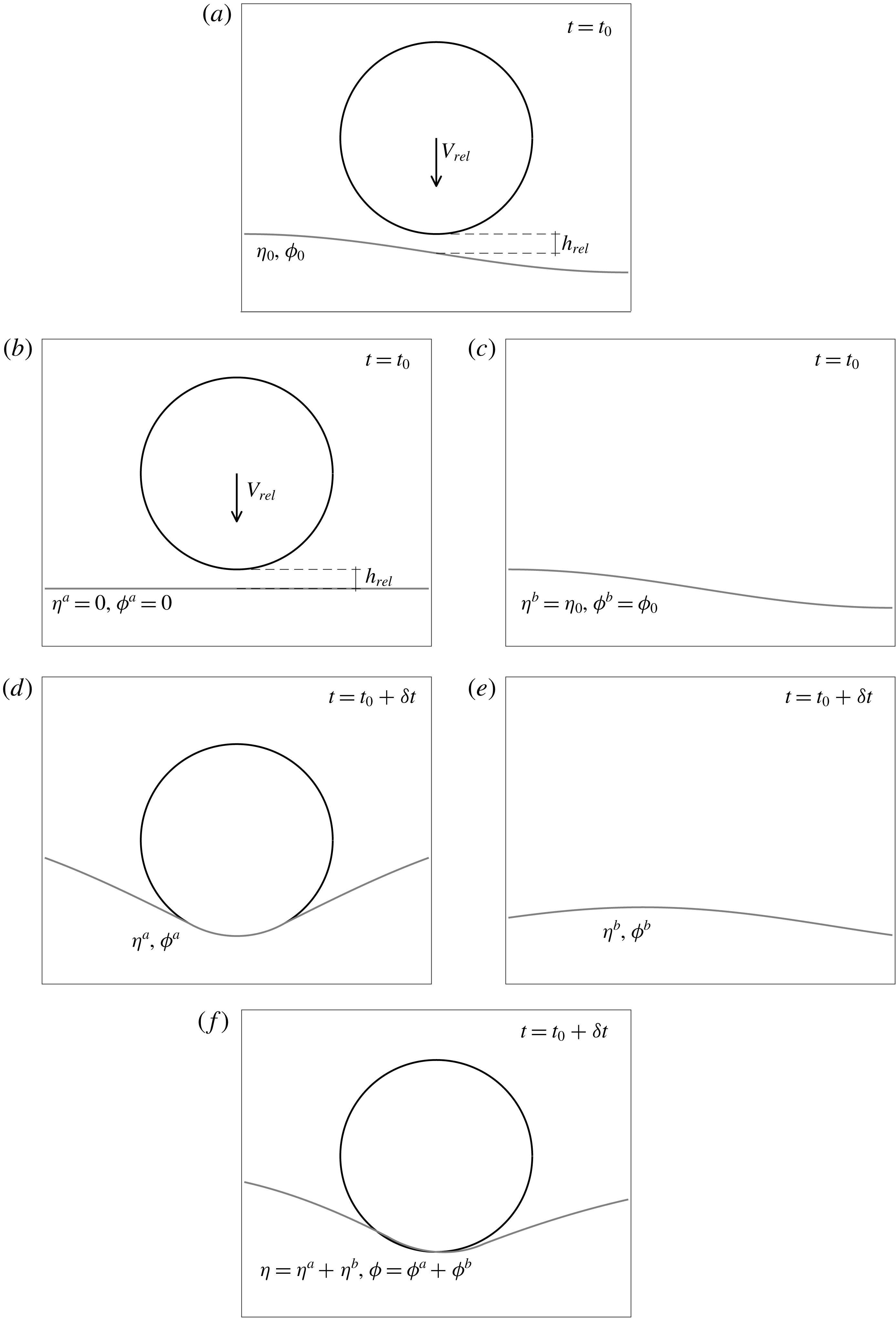
Schematics of the decomposition of the impact of a walking droplet problem into two simpler calculations. Panel (a) shows the initial conditions given by an imminent droplet impact, (b) and (c) show the initial conditions for each of the separate problems, (d) and (e) respectively show the evolution of (b) and (c), and (f) shows how the results (d) and (e) are combined. The sub-index rel indicates magnitudes measured in relation to the point of the free surface that is directly below the south pole of the sphere.

In summary, we model the wave field of a walking droplet by superposing translations of axisymmetric wave fields due to droplet impacts. When the droplet is in flight, we calculate the free-surface evolution by solving the linear equations (2.14) and (2.15), with
 $\unicode[STIX]{x1D705}=\unicode[STIX]{x1D6E5}_{H}$
, and the droplet height from (2.19); all subject to
 $p_{s}(\boldsymbol{x},t)=0$
. When an impact is about to happen, we separate the problem into two (see figure 2). We define problem
 $a$
as the axisymmetric impact of a droplet onto a bath, with the initial conditions
 $\unicode[STIX]{x1D702}^{a}(\boldsymbol{x},t_{0})=0$
and
 $\unicode[STIX]{x1D719}^{a}(\boldsymbol{x},t_{0})=0$
, and the position and velocity of the droplet being such that the relative height and vertical velocity with respect to the surface point exactly below the south pole are the same as in the physical problem (figures 2
b and 2
d). For this problem, we preserve the full curvature
 $\unicode[STIX]{x1D705}$
within
 $A(t)$
, as done in Galeano-Rios et al. (Reference Galeano-Rios, Milewski and Vanden-Broeck2017). We solve the axisymmetric problem
 $a$
until the droplet is once again airborne. In parallel, we define problem
 $b$
in which we find waves
 $\unicode[STIX]{x1D702}^{b}$
and
 $\unicode[STIX]{x1D719}^{b}$
with initial conditions
 $\unicode[STIX]{x1D702}^{b}(\boldsymbol{x},t_{0})=\unicode[STIX]{x1D702}(\boldsymbol{x},t_{0})$
and
 $\unicode[STIX]{x1D719}^{b}(\boldsymbol{x},t_{0})=\unicode[STIX]{x1D719}(\boldsymbol{x},t_{0})$
, but without the pressure induced by the droplet, which is to say we ignore the forcing of the ongoing droplet contact as we solve the wave field (figures 2
c and 2
e). The temporally dependent nature of gravity is preserved in both problems. We then superpose the axisymmetric solution of the droplet impact on the unforced surface waves at the predicted location of the droplet
 $\boldsymbol{X}(t)$
. Once the droplet is again in flight, we carry on solving a single problem, namely that resulting from the superposition.
We note that the vertical droplet motion obtained from the impact on the flat free surface is treated as an approximation to the motion of the actual droplet relative to the point on the fluid surface that is directly under the south pole of the droplet. That is to say, the height and velocities of the droplet as obtained from the impact of a flat interface will be added to the height and velocity of the fluid surface at the
 $\boldsymbol{X}(t)$
location in order to obtain the prediction for the height of the droplet for
 $t\in [t_{0},t_{l}]$
. We highlight that this superposition does not result in a perfect match of the surfaces (see figure 2
f); however, it still yields an exact match between the south pole of the droplet and the corresponding point of the free surface. The mismatch between the sphere and the free surface of the bath is of the order of the wave gradient in problem
 $b$
, i.e.
 $\unicode[STIX]{x1D716}/\unicode[STIX]{x1D706}_{F}=O(10^{-3})$
, multiplied by the radius of the typical pressed area (
 ${\leqslant}0.5R_{o}$
). Therefore, the typical mismatch is of
 $O(10^{-3})$
when expressed as a fraction of the droplet radius.
2.4 Horizontal dynamics
We derive equations for the horizontal motion of the sphere on the basis of the approximations introduced in § 2.3. For impacts, we arrive at a model that includes the horizontal components of the pressure forces that were previously discussed in § 2.2.2, as well as a drag force due to a simplified model of viscous forces in the intervening air layer similar to the one presented in Couder et al. (Reference Couder, Fort, Gautier and Boudaoud2005a ) and Protière, Boudaoud & Couder (Reference Protière, Boudaoud and Couder2006). The main advantage of the derivation presented in what follows is that we are able to include the effect of changes in pressed area over each contact of the droplet.
The horizontal motion of the droplet, expressed in dimensionless variables, is governed by
 $$\begin{eqnarray}\displaystyle \boldsymbol{X}_{tt} & = & \displaystyle {\displaystyle \frac{1}{Ma}}\left(\int _{A(t)}{\displaystyle \frac{-p_{s}\unicode[STIX]{x1D735}\unicode[STIX]{x1D702}}{\sqrt{1+|\unicode[STIX]{x1D735}\unicode[STIX]{x1D702}|^{2}}\,}}\,\text{d}A+\int _{S(t)}(\unicode[STIX]{x1D64F}_{air}\boldsymbol{\cdot }\hat{\boldsymbol{n}})_{H}\,\text{d}S\right.\nonumber\\ \displaystyle & & \displaystyle \left.+\,\int _{S^{2}\setminus S(t)}(-p_{air}\hat{\boldsymbol{n}}+\unicode[STIX]{x1D64F}_{air}\boldsymbol{\cdot }\hat{\boldsymbol{n}})_{H}\,\text{d}S\right),\end{eqnarray}$$
where
 $\unicode[STIX]{x1D64F}_{air}$
is the deviatoric part of the stress tensor for the air flow,
 $\hat{\boldsymbol{n}}$
is the outward-pointing unit normal to the sphere,
 $p_{air}$
is the air pressure, the sub-index
 $H$
indicates the projection onto the
 $xy$
plane,
 $S^{2}$
is the surface of the whole sphere, and we recall that
 $A(t)$
is the horizontal projection of
 $S(t)$
, the portion of the sphere’s surface that is in contact with the free surface of the bath. The first term in parentheses on the right-hand side of (2.46) corresponds to horizontal forces due to pressure between the two free surfaces; the second corresponds to the horizontal component of the viscous effects of the flow of air in the intervening layer; and the third term accounts for the contribution of horizontal forces due to the air, outside of the pressed area.
Given the scaling considerations discussed in § 2.3, the leading-order term for the pressure forces due to impact yields
 $$\begin{eqnarray}\displaystyle -{\displaystyle \frac{1}{Ma}}\int _{A(t)}p_{s}{\displaystyle \frac{\unicode[STIX]{x1D735}\unicode[STIX]{x1D702}}{\sqrt{1+|\unicode[STIX]{x1D735}\unicode[STIX]{x1D702}|^{2}}\,}}\,\text{d}A\approx -\unicode[STIX]{x1D735}\unicode[STIX]{x1D702}^{b}|_{(\boldsymbol{X}(t),t)}{\displaystyle \frac{1}{Ma}}\int _{A^{a}(t)}p_{s}^{a}\,\text{d}A, & & \displaystyle\end{eqnarray}$$
where we have also used the assumption that, since surface waves are long when compared to the droplet diameter, the local average of the gradient is approximately equal to
 $\unicode[STIX]{x1D735}\unicode[STIX]{x1D702}^{b}(\boldsymbol{X}(t),t)$
.
Since we are not simulating the air flow, we approximate the effect of the deviatoric stresses within the pressed area by
 $$\begin{eqnarray}\displaystyle {\displaystyle \frac{1}{Ma}}\int _{A(t)}(\unicode[STIX]{x1D64F}_{air}\boldsymbol{\cdot }\hat{\boldsymbol{n}})_{H}\sqrt{1+|\unicode[STIX]{x1D735}\unicode[STIX]{x1D702}|^{2}}\,\text{d}A\approx -{\displaystyle \frac{E(t)T_{F}}{m_{s}}}\boldsymbol{X}_{t}, & & \displaystyle\end{eqnarray}$$
with
 $E(t)$
being a skidding friction coefficient whose form we discuss below. The third term is approximated using Stokes’ drag, assuming the pressed area is a relatively small fraction of the surface area of the sphere, hence
 $$\begin{eqnarray}\displaystyle {\displaystyle \frac{1}{Ma}}\int _{S^{2}\setminus S(t)}(-p_{air}\hat{\boldsymbol{n}}+\unicode[STIX]{x1D64F}_{air}\boldsymbol{\cdot }\hat{\boldsymbol{n}})_{H}\,\text{d}S\approx So\,\boldsymbol{X}_{t}, & & \displaystyle\end{eqnarray}$$
with
 $So$
as in (2.18). We thus have
 $$\begin{eqnarray}\displaystyle \boldsymbol{X}_{tt}=-D(t)\boldsymbol{X}_{t}-\unicode[STIX]{x1D735}\unicode[STIX]{x1D702}^{b}|_{(\boldsymbol{X}(t),t)}{\displaystyle \frac{1}{Ma}}\int _{A^{a}(t)}p_{s}^{a}\,\text{d}A, & & \displaystyle\end{eqnarray}$$
where
 $D(t)=So+E(t)/(f_{F}m)$
. We note that, during impacts, the term
 $So$
(due to Stokes’ drag) is negligible.
2.4.1 Skidding friction
Realistic modelling of skidding friction due to the air flow within the lubrication layer requires methods that can solve a free-boundary lubrication theory problem on a curved, non-symmetric geometry that deforms, and whose deformation is coupled to droplet and wave motion. Moreover, it is the non-symmetric part of the solution to this problem that must be responsible for drag in walking droplets. Given the complexity of this problem, prior works have introduced different simplifications to address this effect; for instance, Moláček & Bush (Reference Moláček and Bush2013b ) introduced a scaling argument based on the assumption of a constant pressed area and experimental observations of the horizontal coefficient of restitution in single-droplet impacts on a flat interface.
We recall that our model yields a time-dependent pressed area approximation as part of the solution to the axisymmetric problem
 $a$
. This allows for the construction of the first skidding friction model that accounts for the effects of the changes in the pressed area during impacts. We thus revisit skidding friction modelling and we are able to derive a working approximation which yields slightly improved predictions (in terms of comparison to experiments) compared to the existing methods and also offers an explanation as to why two competing approaches used in the past by other groups can be seen as expressions of the same effect when we account for changes in the pressed area over an impact.
Assuming the pressed area
 $A(t)$
is small enough that the part of the sphere in contact with the free surface is almost flat, viscous friction forces in the thin air layer would be approximately given, in dimensional variables, by
 $$\begin{eqnarray}\displaystyle F_{D}=-\unicode[STIX]{x1D707}_{air}|A(t)|\,\overline{\unicode[STIX]{x2202}_{z}\boldsymbol{u}_{H}|_{(z=\unicode[STIX]{x1D702})}}, & & \displaystyle\end{eqnarray}$$
where
 $\unicode[STIX]{x1D707}_{air}$
is the dynamic viscosity of air,
 $|A(t)|$
is the surface area of
 $A(t)$
,
 $\boldsymbol{u}_{H}$
is the horizontal velocity of the air, and the bar indicates the mean in the contact area. The expression under the bar should scale as
 $\boldsymbol{X}_{t}/e$
, where
 $e$
is the width of the air layer, which we assume does not change substantially during the contact time. We thus make the approximation
 $$\begin{eqnarray}\displaystyle F_{D}=-\bar{k}\unicode[STIX]{x1D707}_{air}|A(t)|{\displaystyle \frac{\boldsymbol{X}_{t}}{e}}\approx -k\unicode[STIX]{x1D707}_{air}|A^{a}(t)|{\displaystyle \frac{\boldsymbol{X}_{t}}{R_{o}}}, & & \displaystyle\end{eqnarray}$$
where
 $\bar{k}$
is a scaling factor for the vertical derivative of the horizontal velocity which we absorb into
 $k=\bar{k}R_{o}/e$
, a drag parameter. Moreover, we approximate the pressed area
 $A(t)$
by the disc
 $A^{a}(t)$
. We note that for a typical droplet radius (
 $R_{o}\approx 0.4~\text{mm}$
) and for the typical air layer width (
 $e\approx 2~\unicode[STIX]{x03BC}\text{m}$
) as predicted in Protière et al. (Reference Protière, Boudaoud and Couder2006), we obtain
 $R_{o}/e\approx 200$
, which suggests that the values of the dimensionless coefficient
 $k$
should be of the order of
 $O(100\bar{k})$
.
In principle,
 $k$
could be different for each value of driving acceleration or even impact velocity and impact phase, as well as other factors; however, in the present work, we will treat
 $k$
as constant with respect to those variables. Consequently, in (2.48), we estimate
 $$\begin{eqnarray}\displaystyle E(t)=k{\displaystyle \frac{\unicode[STIX]{x1D707}_{air}}{R_{o}}}|A^{a}(t)|, & & \displaystyle\end{eqnarray}$$
which in (2.50), in dimensionless variables, yields
 $$\begin{eqnarray}\displaystyle \boldsymbol{X}_{tt}=-{\displaystyle \frac{3Da}{4Ra}}\left(6+k{\displaystyle \frac{|A^{a}(t)|}{\unicode[STIX]{x03C0}R_{o}^{2}}}\right)\boldsymbol{X}_{t}-\unicode[STIX]{x1D735}\unicode[STIX]{x1D702}^{b}|_{(\boldsymbol{X},t)}{\displaystyle \frac{1}{Ma}}\int _{A^{a}(t)}p_{s}^{a}\,\text{d}A, & & \displaystyle\end{eqnarray}$$
where
 $Ra=R_{o}^{2}\,f_{F}/\unicode[STIX]{x1D708}_{air}$
and
 $Da=\unicode[STIX]{x1D70C}_{air}/\unicode[STIX]{x1D70C}$
, with
 $\unicode[STIX]{x1D708}_{air}$
and
 $\unicode[STIX]{x1D70C}_{air}$
being the kinematic viscosity and the density of air, respectively. We note that the only undetermined parameter in this equation is
 $k$
, whose value we set as described later in the text. We anticipate, however, that the term
 $k(|A^{a}(t)|/\unicode[STIX]{x03C0}R_{o}^{2})$
will dominate the drag effect, in accordance with the relatively minor effect that air drag during flight has been shown to have; for instance, using the model of Milewski et al. (Reference Milewski, Galeano-Rios, Nachbin and Bush2015), we see nearly unchanging walking speeds with or without Stokes’ drag.
3 Solution
For completeness, and given the complexity of the full model, we summarise it below together with a discussion of the numerical techniques used.
When the droplet is in flight, we solve
 $$\begin{eqnarray}\displaystyle & \displaystyle \unicode[STIX]{x1D702}_{t}={\displaystyle \frac{2}{Re}}\unicode[STIX]{x1D6E5}_{H}\unicode[STIX]{x1D702}+N\unicode[STIX]{x1D719}, & \displaystyle\end{eqnarray}$$
 $$\begin{eqnarray}\displaystyle & \displaystyle \unicode[STIX]{x1D719}_{t}=-{\displaystyle \frac{(1-\unicode[STIX]{x1D6E4}\cos (4\unicode[STIX]{x03C0}t))}{Fr}}\unicode[STIX]{x1D702}+{\displaystyle \frac{1}{We}}\unicode[STIX]{x1D6E5}_{H}\unicode[STIX]{x1D702}+{\displaystyle \frac{2}{Re}}\unicode[STIX]{x1D6E5}_{H}\unicode[STIX]{x1D719}, & \displaystyle\end{eqnarray}$$
 $$\begin{eqnarray}\displaystyle & \displaystyle h_{tt}=-{\displaystyle \frac{(1-\unicode[STIX]{x1D6E4}\cos (4\unicode[STIX]{x03C0}t))}{Fr}}-So\,h_{t}, & \displaystyle\end{eqnarray}$$
 $$\begin{eqnarray}\displaystyle & \displaystyle \boldsymbol{X}_{tt}=-{\displaystyle \frac{9Da}{2Ra}}\boldsymbol{X}_{t}, & \displaystyle\end{eqnarray}$$
for
 $\unicode[STIX]{x1D702}$
,
 $\unicode[STIX]{x1D719}$
,
 $h$
and
 $\boldsymbol{X}$
. This is done using a spectral method in space, a second-order Runge–Kutta method in time for (3.1) and (3.2) with a fixed time step, following Milewski et al. (Reference Milewski, Galeano-Rios, Nachbin and Bush2015), and exact integration for (3.3) and (3.4). Care is taken to ensure that the periodic domain used in the spectral method is large enough to guarantee that the waves have decayed at the boundary, mimicking the conditions
 $\unicode[STIX]{x1D702}\rightarrow 0$
when
 $\sqrt{x^{2}+y^{2}}\rightarrow \infty$
; and
 $\unicode[STIX]{x1D719}\rightarrow 0$
when
 $\sqrt{x^{2}+y^{2}}\rightarrow \infty$
. More specifically, we find that a domain of
 $40\unicode[STIX]{x1D706}_{F}\times 40\unicode[STIX]{x1D706}_{F}$
is sufficient for all simulations considered here, the spatial mesh for the unforced wave field is set to have
 $2^{11}\times 2^{11}$
points, and the regular temporal mesh is set to have 80 time steps per Faraday period.
When the method described above yields
 $h(t)\leqslant \unicode[STIX]{x1D702}(\boldsymbol{X}(t),t)$
, i.e. the sphere and the bath are overlapping, we discard this step and we define the previous discrete time in the simulation as
 $t=t_{0}$
. We then define
 $$\begin{eqnarray}\displaystyle \unicode[STIX]{x1D702}^{a}(\boldsymbol{x},t_{0})=0,\quad \unicode[STIX]{x1D702}^{b}(\boldsymbol{x},t_{0})=\unicode[STIX]{x1D702}(\boldsymbol{x},t_{0}), & & \displaystyle\end{eqnarray}$$
 $$\begin{eqnarray}\displaystyle \unicode[STIX]{x1D719}^{a}(\boldsymbol{x},t_{0})=0,\quad \unicode[STIX]{x1D719}^{b}(\boldsymbol{x},t_{0})=\unicode[STIX]{x1D719}(\boldsymbol{x},t_{0}), & & \displaystyle\end{eqnarray}$$
 $$\begin{eqnarray}\displaystyle h^{a}(t_{0})=h(t_{0})-\unicode[STIX]{x1D702}(\boldsymbol{X}(t_{0}),t_{0}),\quad h^{b}(t_{0})=\unicode[STIX]{x1D702}^{b}(\boldsymbol{X}(t_{0}),t_{0}), & & \displaystyle\end{eqnarray}$$
 $$\begin{eqnarray}\displaystyle h_{t}^{a}(t_{0})=h_{t}(t_{0})-\unicode[STIX]{x1D702}_{t}(\boldsymbol{X}(t_{0}),t_{0}),\quad h_{t}^{b}(t_{0})=\unicode[STIX]{x1D702}_{t}^{b}(\boldsymbol{X}(t_{0}),t_{0}), & & \displaystyle\end{eqnarray}$$
and we solve independent problems for initial conditions
 $a$
and
 $b$
.
The axisymmetric, forced problem for the impact is given by
 $$\begin{eqnarray}\displaystyle & \displaystyle \unicode[STIX]{x1D702}_{t}^{a}={\displaystyle \frac{2}{Re}}\unicode[STIX]{x1D6E5}_{H}\unicode[STIX]{x1D702}^{a}+N\unicode[STIX]{x1D719}^{a},\quad z=0, & \displaystyle\end{eqnarray}$$
 $$\begin{eqnarray}\displaystyle & \displaystyle \unicode[STIX]{x1D719}_{t}^{a}=-{\displaystyle \frac{(1-\unicode[STIX]{x1D6E4}\cos (4\unicode[STIX]{x03C0}t))}{Fr}}\unicode[STIX]{x1D702}^{a}+{\displaystyle \frac{1}{We}}\unicode[STIX]{x1D705}[\unicode[STIX]{x1D702}^{a}]+{\displaystyle \frac{2}{Re}}\unicode[STIX]{x1D6E5}_{H}\unicode[STIX]{x1D719}^{a}-p_{s}^{a},\quad z=0, & \displaystyle\end{eqnarray}$$
 $$\begin{eqnarray}\displaystyle & \displaystyle h_{tt}^{a}=-{\displaystyle \frac{(1-\unicode[STIX]{x1D6E4}\cos (4\unicode[STIX]{x03C0}t))}{Fr}}-So\,h_{t}^{a}+{\displaystyle \frac{1}{Ma}}\int _{A^{a}(t)}p_{s}^{a}\,\text{d}A, & \displaystyle\end{eqnarray}$$
subject to
 $\unicode[STIX]{x1D702}^{a}\rightarrow 0$
when
 $\sqrt{x^{2}+y^{2}}\rightarrow \infty$
;
 $\unicode[STIX]{x1D719}^{a}\rightarrow 0$
when
 $\sqrt{x^{2}+y^{2}+z^{2}}\rightarrow \infty$
; and
 $$\begin{eqnarray}\displaystyle & \displaystyle \unicode[STIX]{x1D702}^{a}(\boldsymbol{x},t)=h^{a}(t)+z_{s}(\boldsymbol{x}),\quad \boldsymbol{x}\in A^{a}(t), & \displaystyle\end{eqnarray}$$
 $$\begin{eqnarray}\displaystyle & \displaystyle \unicode[STIX]{x1D702}^{a}(\boldsymbol{x},t)<h^{a}(t)+z_{s}(\boldsymbol{x}),\quad \boldsymbol{x}\notin A^{a}(t), & \displaystyle\end{eqnarray}$$
 $$\begin{eqnarray}\displaystyle & \displaystyle p_{s}^{a}(\boldsymbol{x},t)=0,\quad \boldsymbol{x}\notin A^{a}(t), & \displaystyle\end{eqnarray}$$
 $$\begin{eqnarray}\displaystyle & \displaystyle \unicode[STIX]{x2202}_{n}\unicode[STIX]{x1D702}^{a}(\boldsymbol{x},t)=\unicode[STIX]{x2202}_{n}z_{s}(\boldsymbol{x}),\quad \boldsymbol{x}\in L^{a}(t), & \displaystyle\end{eqnarray}$$
whilst also assuming that
 $\unicode[STIX]{x1D705}[\unicode[STIX]{x1D702}^{a}(\boldsymbol{x},t)]\approx \unicode[STIX]{x1D6E5}_{H}\unicode[STIX]{x1D702}^{a}(\boldsymbol{x},t)$
, when
 $\boldsymbol{x}\notin A^{a}(t)$
. This problem is solved using finite differences and a numerical approximation to the singular integral operator
 $N$
(following Galeano-Rios et al. (Reference Galeano-Rios, Milewski and Vanden-Broeck2017)), in space; and implicit Euler in time, with an adaptive time step. The axisymmetric domain size is set to
 $2\unicode[STIX]{x1D706}_{F}$
, the spatial mesh size is set for each droplet size to
 $R_{o}/40$
, and the adaptive time step is always chosen as a refinement of the temporal mesh of the unforced problem. The solution to this problem is calculated until
 $t=t_{l}$
, by which the droplet is once again in flight.
In parallel, we solve the homogeneous non-axisymmetric problem
 $$\begin{eqnarray}\displaystyle & \displaystyle \unicode[STIX]{x1D702}_{t}^{b}={\displaystyle \frac{2}{Re}}\unicode[STIX]{x1D6E5}_{H}\unicode[STIX]{x1D702}^{b}+N\unicode[STIX]{x1D719}^{b}, & \displaystyle\end{eqnarray}$$
 $$\begin{eqnarray}\displaystyle & \displaystyle \unicode[STIX]{x1D719}_{t}^{b}=-{\displaystyle \frac{(1-\unicode[STIX]{x1D6E4}\cos (4\unicode[STIX]{x03C0}t))}{Fr}}\unicode[STIX]{x1D702}^{b}+{\displaystyle \frac{1}{We}}\unicode[STIX]{x1D6E5}_{H}\unicode[STIX]{x1D702}^{b}+{\displaystyle \frac{2}{Re}}\unicode[STIX]{x1D6E5}_{H}\unicode[STIX]{x1D719}^{b}, & \displaystyle\end{eqnarray}$$
subject to
 $\unicode[STIX]{x1D702}^{b}\rightarrow 0$
when
 $\sqrt{x^{2}+y^{2}}\rightarrow \infty$
; and
 $\unicode[STIX]{x1D719}^{b}\rightarrow 0$
when
 $\sqrt{x^{2}+y^{2}}\rightarrow \infty$
, from
 $t=t_{0}$
to
 $t=t_{l}$
; and we define
 $$\begin{eqnarray}\displaystyle h^{b}(t)=\unicode[STIX]{x1D702}^{b}(\boldsymbol{X}(t),t),\quad h_{t}^{b}(t)=\unicode[STIX]{x1D702}_{t}^{b}(\boldsymbol{X}(t),t), & & \displaystyle\end{eqnarray}$$
for
 $t\in [t_{0},t_{l}]$
.
The horizontal motion of the particle for
 $t\in [t_{0},t_{l}]$
is computed by solving
 $$\begin{eqnarray}\displaystyle \boldsymbol{X}_{tt}=-{\displaystyle \frac{3Da}{4Ra}}\left(6+k{\displaystyle \frac{|A^{a}(t)|}{\unicode[STIX]{x03C0}R_{o}^{2}}}\right)\boldsymbol{X}_{t}-\unicode[STIX]{x1D735}\unicode[STIX]{x1D702}^{b}|_{(\boldsymbol{X}(t),t)}{\displaystyle \frac{1}{Ma}}\int _{A^{a}(t)}p_{s}^{a}\,\text{d}A, & & \displaystyle\end{eqnarray}$$
with a semi-implicit Euler method.
The solutions
 $\unicode[STIX]{x1D702}$
,
 $\unicode[STIX]{x1D719}$
,
 $h$
and
 $h_{t}$
for
 $t\in [t_{0},t_{l}]$
are thus given by
 $$\begin{eqnarray}\displaystyle & \displaystyle \unicode[STIX]{x1D702}(\boldsymbol{x},t)=\unicode[STIX]{x1D702}^{a}(\boldsymbol{x}-\boldsymbol{X}(t),t)+\unicode[STIX]{x1D702}^{b}(\boldsymbol{x},t), & \displaystyle\end{eqnarray}$$
 $$\begin{eqnarray}\displaystyle & \displaystyle \unicode[STIX]{x1D719}(\boldsymbol{x},t)=\unicode[STIX]{x1D719}^{a}(\boldsymbol{x}-\boldsymbol{X}(t),t)+\unicode[STIX]{x1D719}^{b}(\boldsymbol{x},t), & \displaystyle\end{eqnarray}$$
 $$\begin{eqnarray}\displaystyle & \displaystyle h(t)=h^{a}(t)+h^{b}(t), & \displaystyle\end{eqnarray}$$
 $$\begin{eqnarray}\displaystyle & \displaystyle h_{t}(t)=h_{t}^{a}(t)+h_{t}^{b}(t), & \displaystyle\end{eqnarray}$$
at which point the droplet is once again in flight and we can repeat the procedure.
In summary, when an impact is about to take place, we first solve an axisymmetric impact until a time which we define as
 $t_{l}$
, when the droplet has lifted off. From this problem, we find the vertical forces on the droplet and the surface deflection due to the impact. In parallel, we evolve the unforced surface waves until
 $t=t_{l}$
. We take the information of the surface elevation gradient of the unforced waves, at the location given by the droplet position, and we compute the horizontal motion of the droplet. Finally, we superpose the axisymmetric wave from problem
 $a$
to the solution of problem
 $b$
, at the corresponding location
 $\boldsymbol{X}(t)$
.
There are several advantages to the approach taken here. For instance, the impact problem can be solved in a smaller domain, as this domain only needs to be large enough to guarantee that the waves have not reached its boundary over the duration of an impact. This allows for a much finer mesh, with respect to that reported in Galeano-Rios et al. (Reference Galeano-Rios, Milewski and Vanden-Broeck2017), to be used to solve the impact problem whilst still allowing much faster computations. Conversely, the wave propagation without the impact can be solved using a much coarser mesh than was used in Galeano-Rios et al. (Reference Galeano-Rios, Milewski and Vanden-Broeck2017), since the typical wavelength is large in comparison to the droplet. More importantly, we are able to use a Fourier method for the unforced waves, which diagonalises the Laplacian operators. Similarly, we can use a much finer time step for the impacts, which allows for an improved resolution of the vertical forces on the droplet with respect to what was obtained in Galeano-Rios et al. (Reference Galeano-Rios, Milewski and Vanden-Broeck2017), whilst we use a coarser time mesh for the unforced wave propagation problem, allowing for faster computations. In § 4, we show that the approximation method described above also provides increased accuracy.
3.1 Simulations
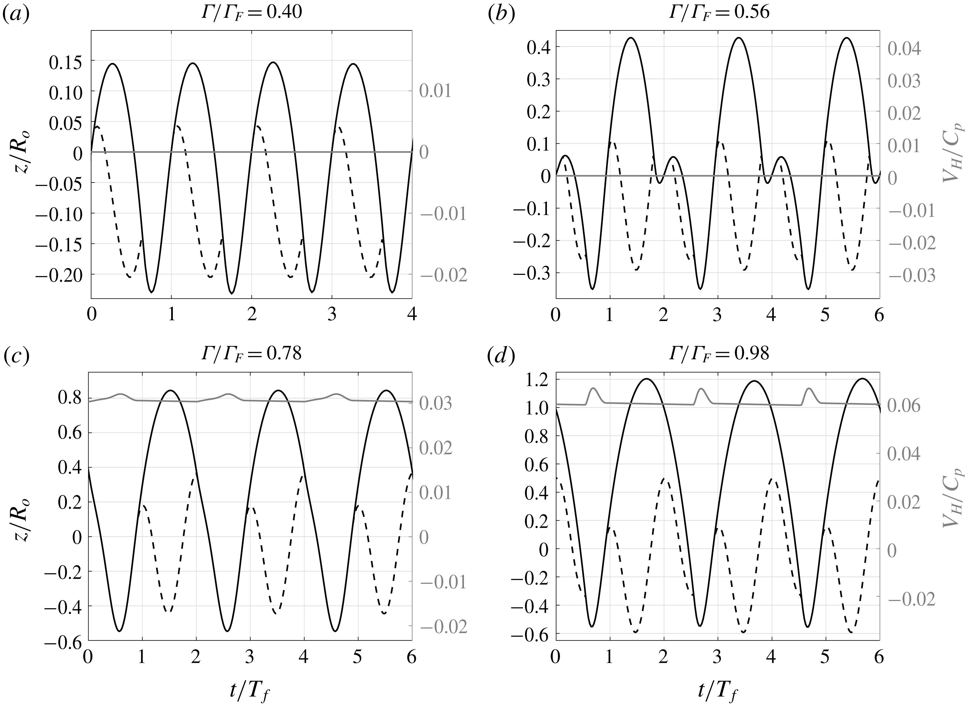
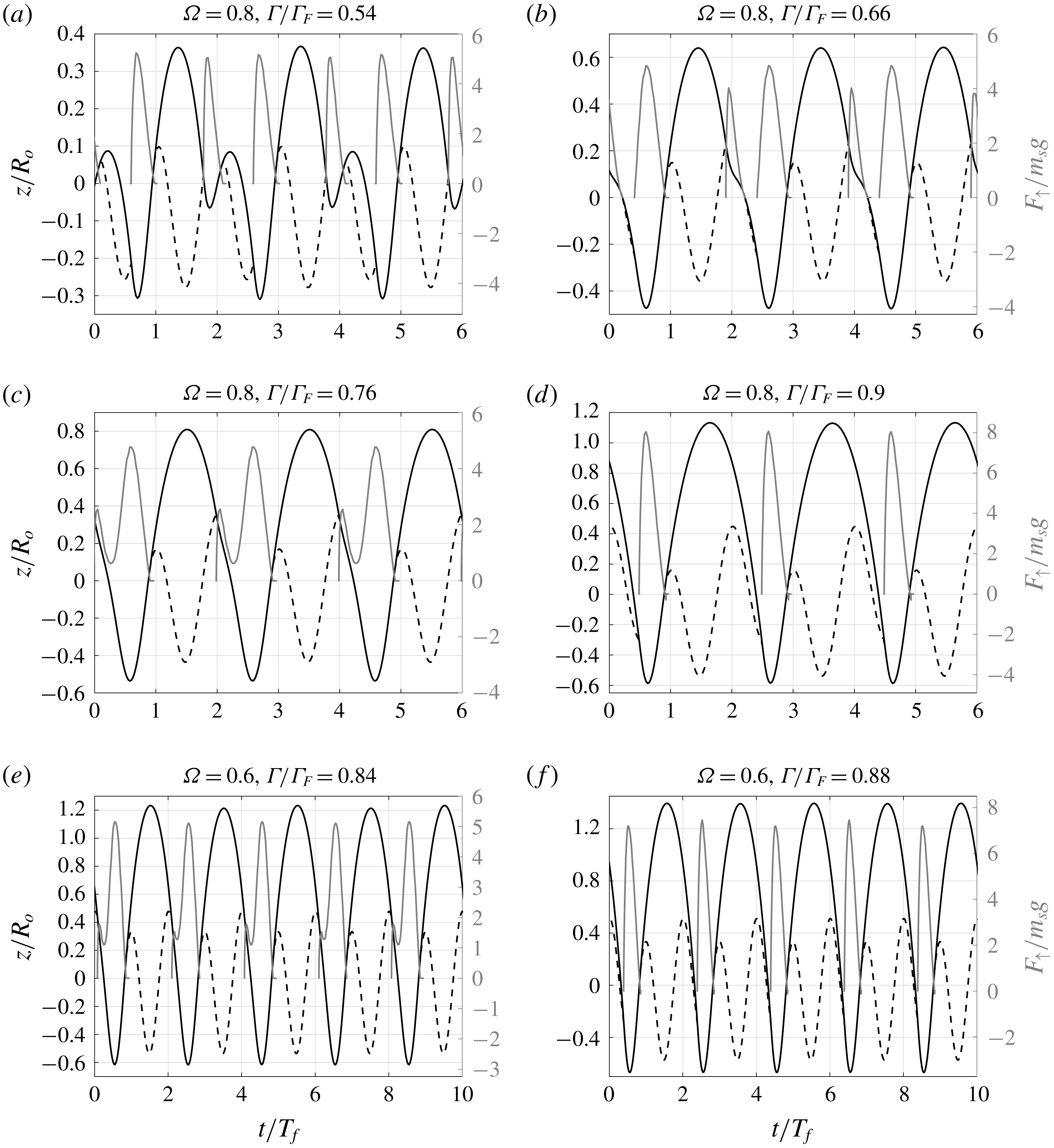
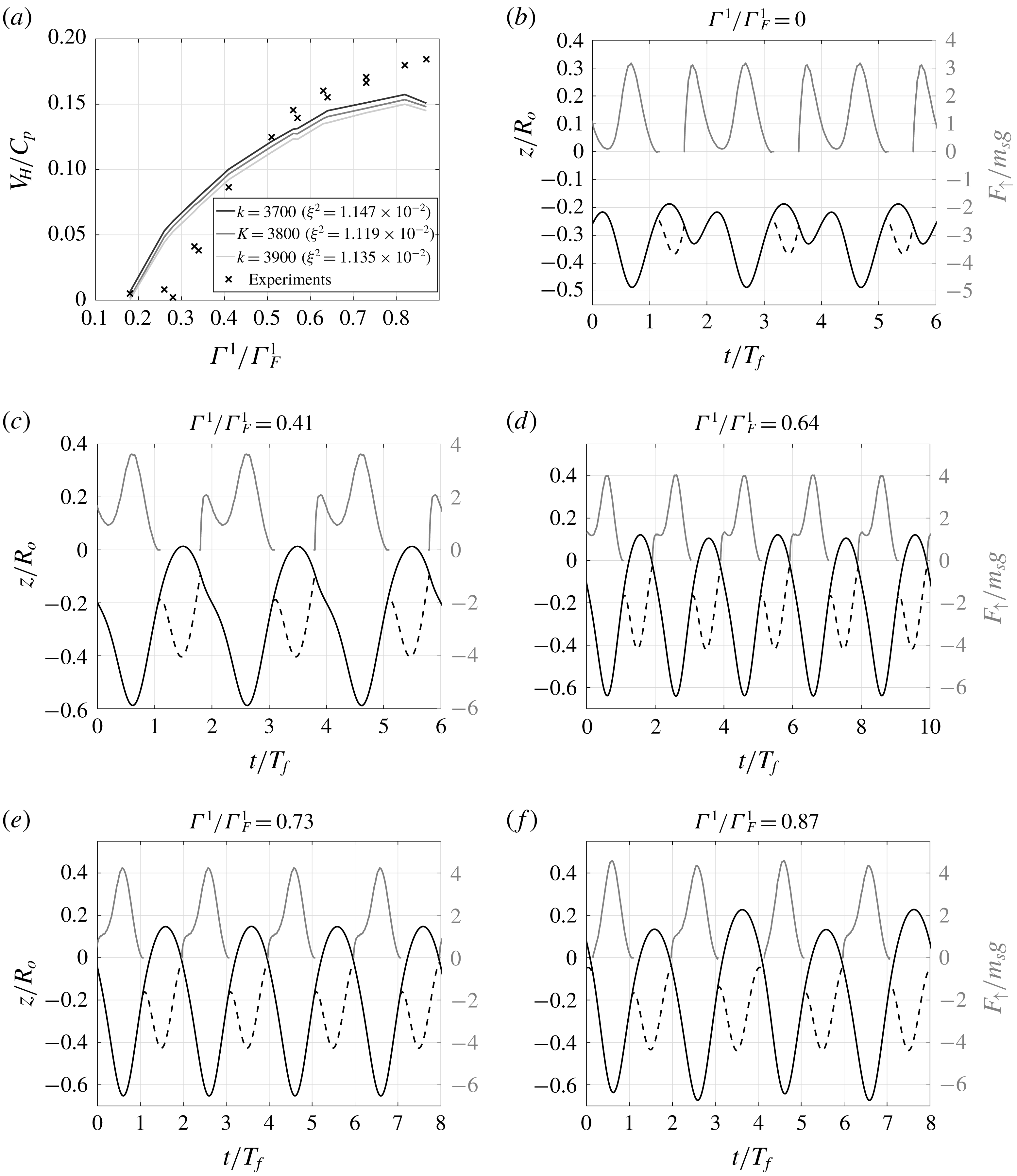
Simulation results for droplets walking at different driving accelerations (
 $\unicode[STIX]{x1D6E4}$
). Solid black lines show the trajectory of the south pole of the droplet and dashed lines correspond to the point of the free surface just under the south pole. Grey lines show the horizontal speed of the droplets. Here
 $C_{p}$
is the phase velocity of the Faraday waves (
 $C_{p}=19.88~\text{cm}~\text{s}^{-1}$
), and
 $T_{f}$
is the forcing period. All panels correspond to a droplet of radius
 $R_{o}=0.38~\text{mm}$
, i.e. vibration number
 $\unicode[STIX]{x1D6FA}=0.8$
(
 $\unicode[STIX]{x1D6FA}=\unicode[STIX]{x1D714}_{o}\sqrt{\unicode[STIX]{x1D70C}R_{o}^{3}/\unicode[STIX]{x1D70E}}$
) and drag parameter
 $k=3100$
. Panels (a–c) and (d) correspond to modes
 $(1,1)$
,
 $(2,2)$
,
 $(2,1)^{1}$
and
 $(2,1)^{2}$
, respectively.

Simulations are initiated by imparting the droplet with a horizontal velocity of
 $0.1C_{p}$
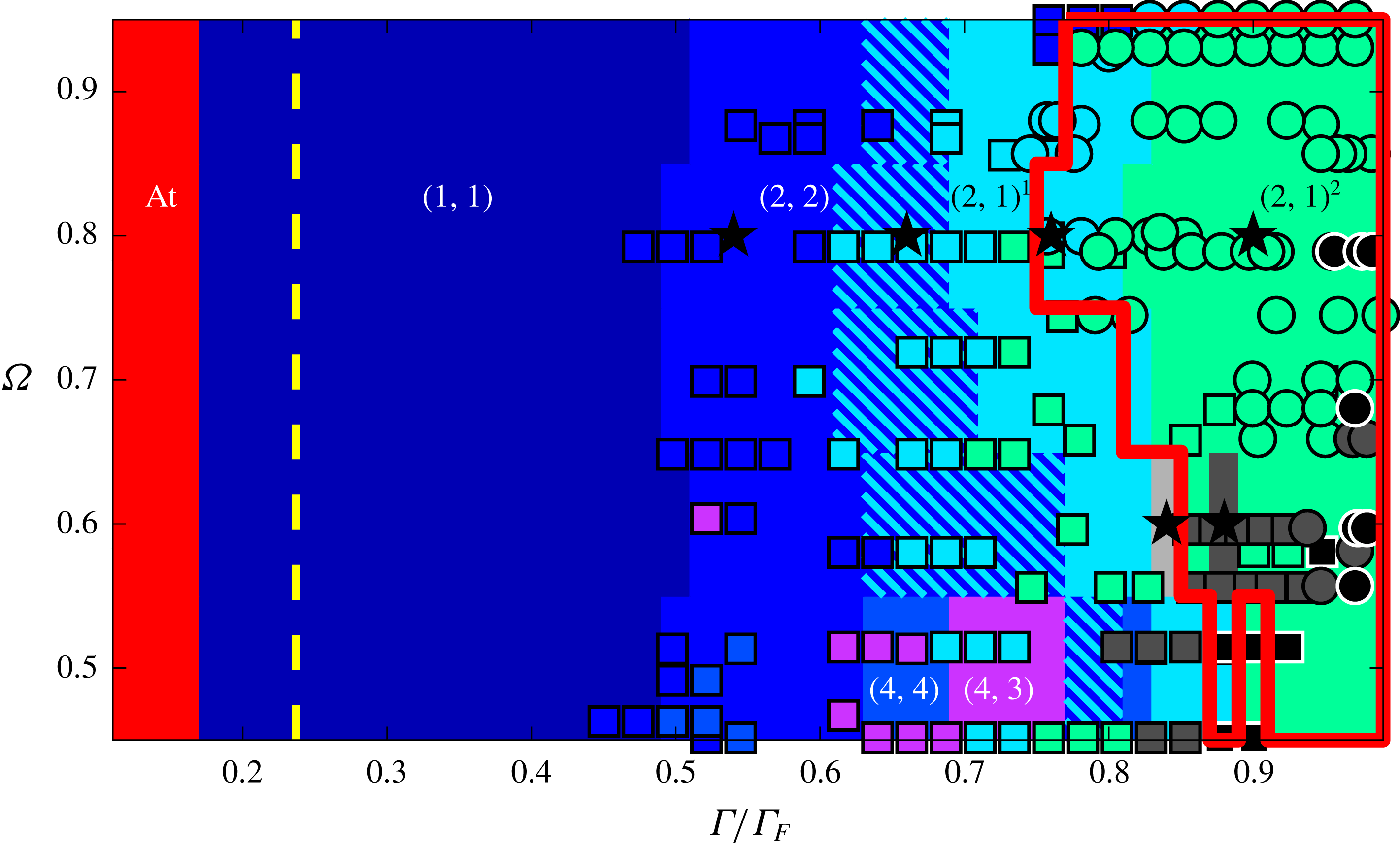
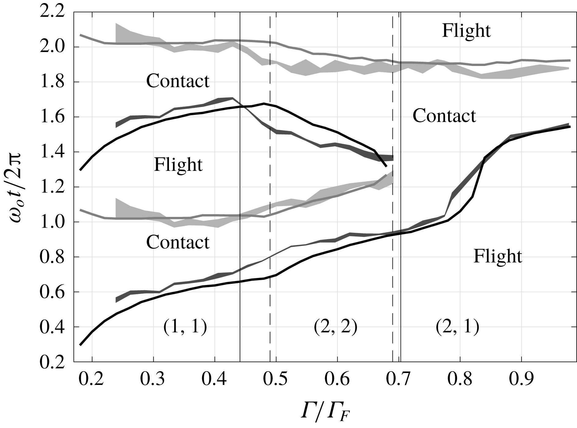
and with a downward vertical velocity that is in the typical range for walking droplets; all while the droplet is slightly above the surface. Droplets will then settle onto a steady walking speed or come to a halt, if the system parameters do not allow steady walking. We are able to identify the known bouncing modes which we describe with the ordered pairs
 $(m,n)$
, following Gilet & Bush (Reference Gilet and Bush2009) and Moláček & Bush (Reference Moláček and Bush2013a
), in which
 $m$
stands for the number of forcing periods contained in a complete period of vertical motion, and
 $n$
corresponds to the number of contacts that take place during
 $m$
forcing periods. These different modes can be identified in figure 3, in which droplet contacts correspond to the time intervals over which the south pole coincides with the free surface. We are also able to distinguish variants within the same
 $(m,n)$
mode, such as the
 $(2,1)^{1}$
and
 $(2,1)^{2}$
(see figures 3
c and 3
d). We discuss the distinction of these modes in greater detail later in the text.
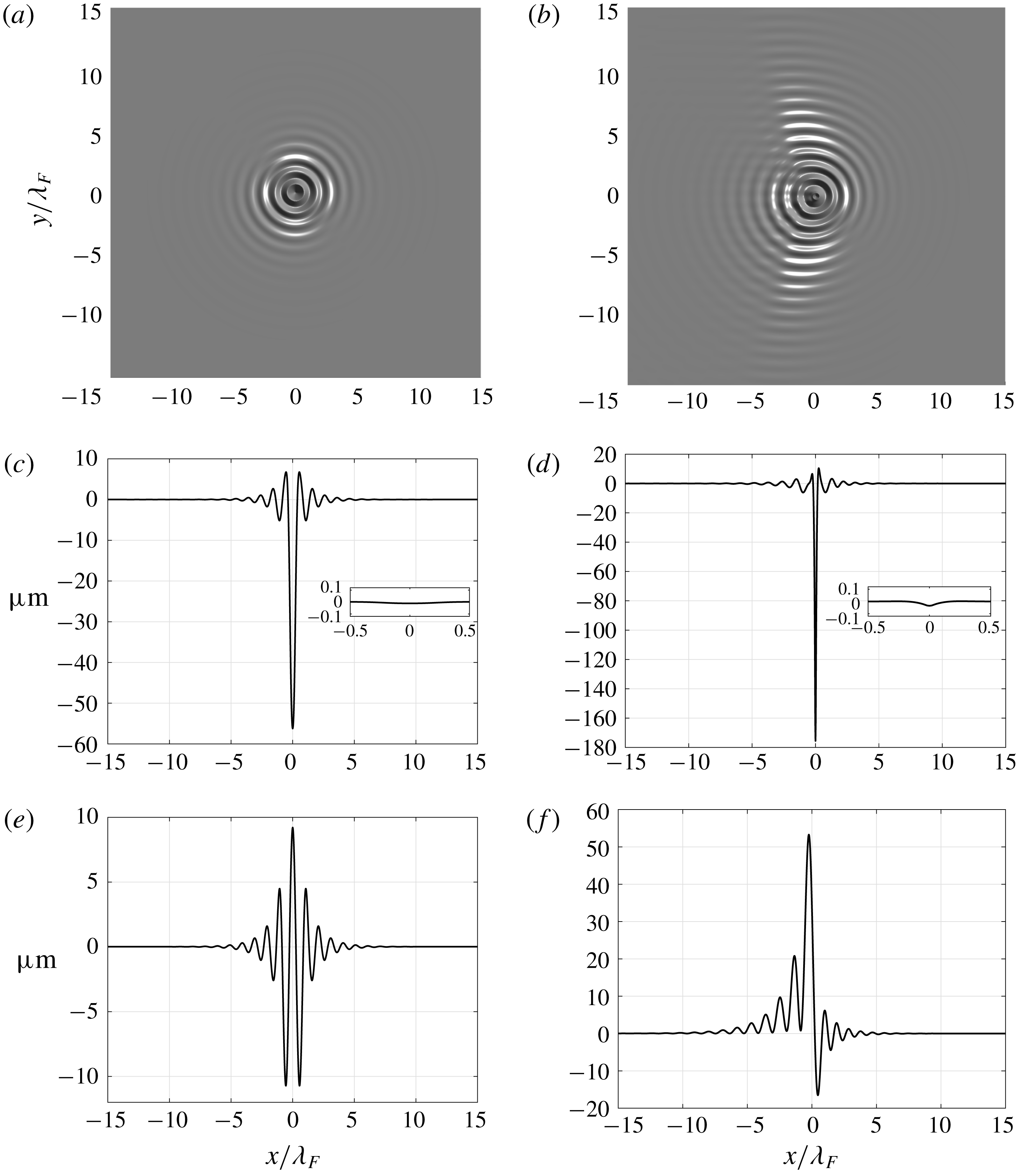
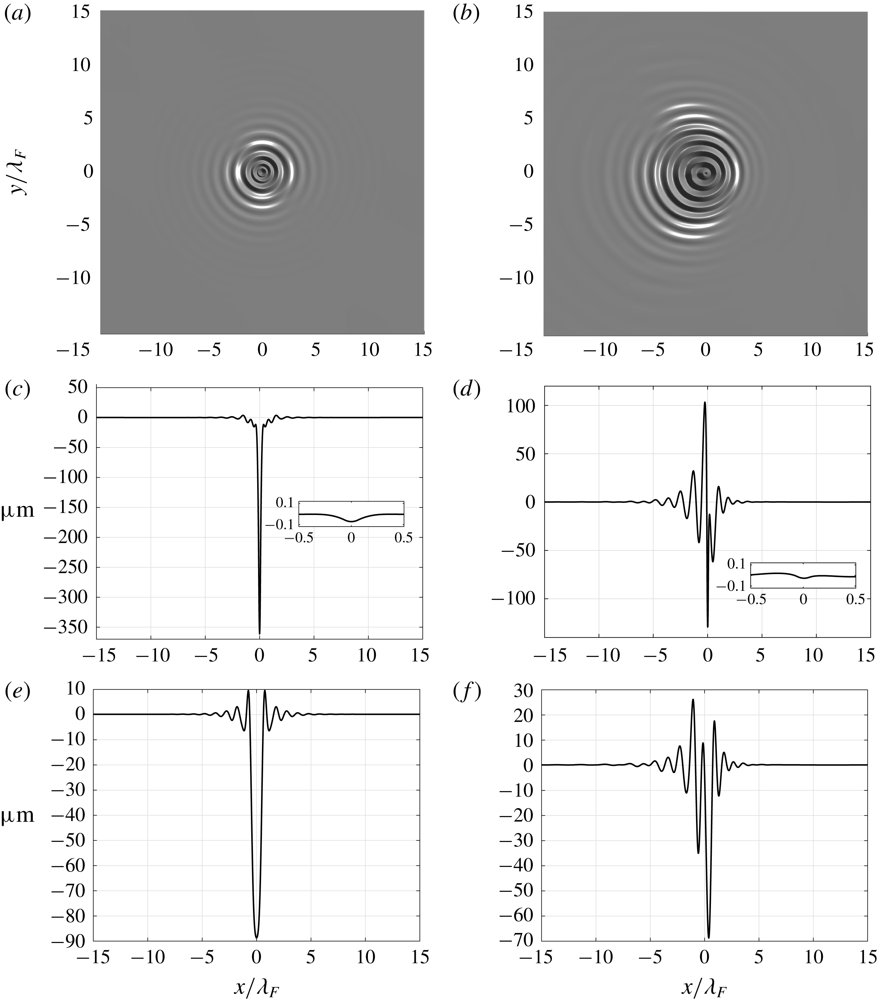
Wave field simulations for vibration number
 $\unicode[STIX]{x1D6FA}=0.8$
and drag parameter
 $k=3100$
. (a) Bouncer at
 $\unicode[STIX]{x1D6E4}/\unicode[STIX]{x1D6E4}_{F}=0.74$
, with (c) its cross-section at
 $y=0$
. (b) Walker moving to the right at
 $\unicode[STIX]{x1D6E4}/\unicode[STIX]{x1D6E4}_{F}=0.98$
, with (d) its section along the direction of walking. The wave field in panels (a–c) and (d) is sampled at the time of maximum absolute surface deflection and with
 $\boldsymbol{X}(t)=(0,0)$
. The inset plots in panels (c) and (d) show a close-up of the wave field at the impact location using the same vertical and horizontal scale (units of
 $\unicode[STIX]{x1D706}_{F}$
). The cross-sections in panels (e) and (f) are analogous to those in (c) and (d), respectively; though in (e) and (f) the section is obtained just before a droplet impact. Animations of the wave field and droplet motion for these two simulations are included as supplementary movies available at https://doi.org/10.1017/jfm.2019.409. We note that the panels do not show the totality of the computational domain.

Figure 4 shows the simulation of the wave fields of a bouncer and a walker, which display the typical features reported in Eddi et al. (Reference Eddi, Sultan, Moukhtar, Fort, Rossi and Couder2011). We highlight that the vertical scale in figure 4(c–f) is greatly exaggerated in order to provide a quantitative comparison of the scales of the unforced waves and the impact dimple. This might create the illusion of a non-smooth interface. The inset plots in figure 4(c) and (d) (for which we use the same scale in
 $x$
and
 $z$
) show that the free surface is in fact very smooth. Animations of the simulations presented in figure 4 are provided as supplementary movies; these also clearly portray the surface smoothness.
We run simulations of walking droplets in the parameter regimes investigated experimentally by previous works (Moláček & Bush Reference Moláček and Bush2013b
; Wind-Willassen et al.
Reference Wind-Willassen, Moláek, Harris and Bush2013; Pucci et al.
Reference Pucci, Sáenz, Faria and Bush2016) with the experimental set-up of
 $20~\text{cSt}$
and
 $80~\text{Hz}$
(see appendix A) for different values of the vibration number
 $\unicode[STIX]{x1D6FA}=\unicode[STIX]{x1D714}_{o}\sqrt{\unicode[STIX]{x1D70C}R_{o}^{3}/\unicode[STIX]{x1D70E}}$
(as defined in Dorbolo et al. (Reference Dorbolo, Terwagne, Vandewalle and Gilet2008)); we then compare their experimental reports to our simulation results for different values of the skidding friction parameter
 $k$
. We use the comparison to define an adequate value of
 $k$
for each
 $\unicode[STIX]{x1D6FA}$
and complete our skidding friction model. We note that, since all other parameters involved in the definition of
 $\unicode[STIX]{x1D6FA}$
are fixed for this study,
 $\unicode[STIX]{x1D6FA}$
can be simply considered as a proxy for the droplet radius.
3.1.1 Optimal values of
 $k$

Protière et al. (Reference Protière, Boudaoud and Couder2006) proposed a skidding friction model in which viscous effects yield a force that is proportional to droplet speed, where the proportionality constants were estimated on the basis of typical sizes for the contact area and air layer width. Moláček & Bush (Reference Moláček and Bush2013b ) presented a different skidding friction model in which the horizontal drag force due to the motion of the droplet as it slides on the surface is considered to be proportional to the vertical force exerted on the droplet, and to the droplet speed. They arrived at this form for the drag by means of experimental measurements of the horizontal coefficient of restitution of droplets impacting a bath at different angles. They go on to fit the resulting data of tangential coefficient of restitution as a function of the Weber number and interpret their findings as implying that the dominant effect for horizontal drag is momentum transference to the fluid bath. Moreover, they assume throughout their work that the pressed area is roughly constant.
Our present approach is similar to that of Protière et al. (Reference Protière, Boudaoud and Couder2006); however, we are able to consider the change in contact area during each impact. We obtain, as shown in (2.52), a friction model that is proportional to the instantaneous value of the contact area and to the droplet’s velocity. Nevertheless, in Galeano-Rios et al. (Reference Galeano-Rios, Milewski and Vanden-Broeck2017) it was shown that the pressed area and the vertical force are roughly proportional; therefore, a model that accounts for pressed area variations will produce a skidding friction term that is approximately proportional to forces and droplet speeds. Thus, when we account for the effects of the varying pressed area, we can reinterpret the findings of Moláček & Bush (Reference Moláček and Bush2013b ) as not being incompatible with those of Protière et al. (Reference Protière, Boudaoud and Couder2006). In particular, we can justify the form of the friction term given in Moláček & Bush (Reference Moláček and Bush2013b ) whilst still considering viscous effects as the main drivers of the resistance to motion during contact.
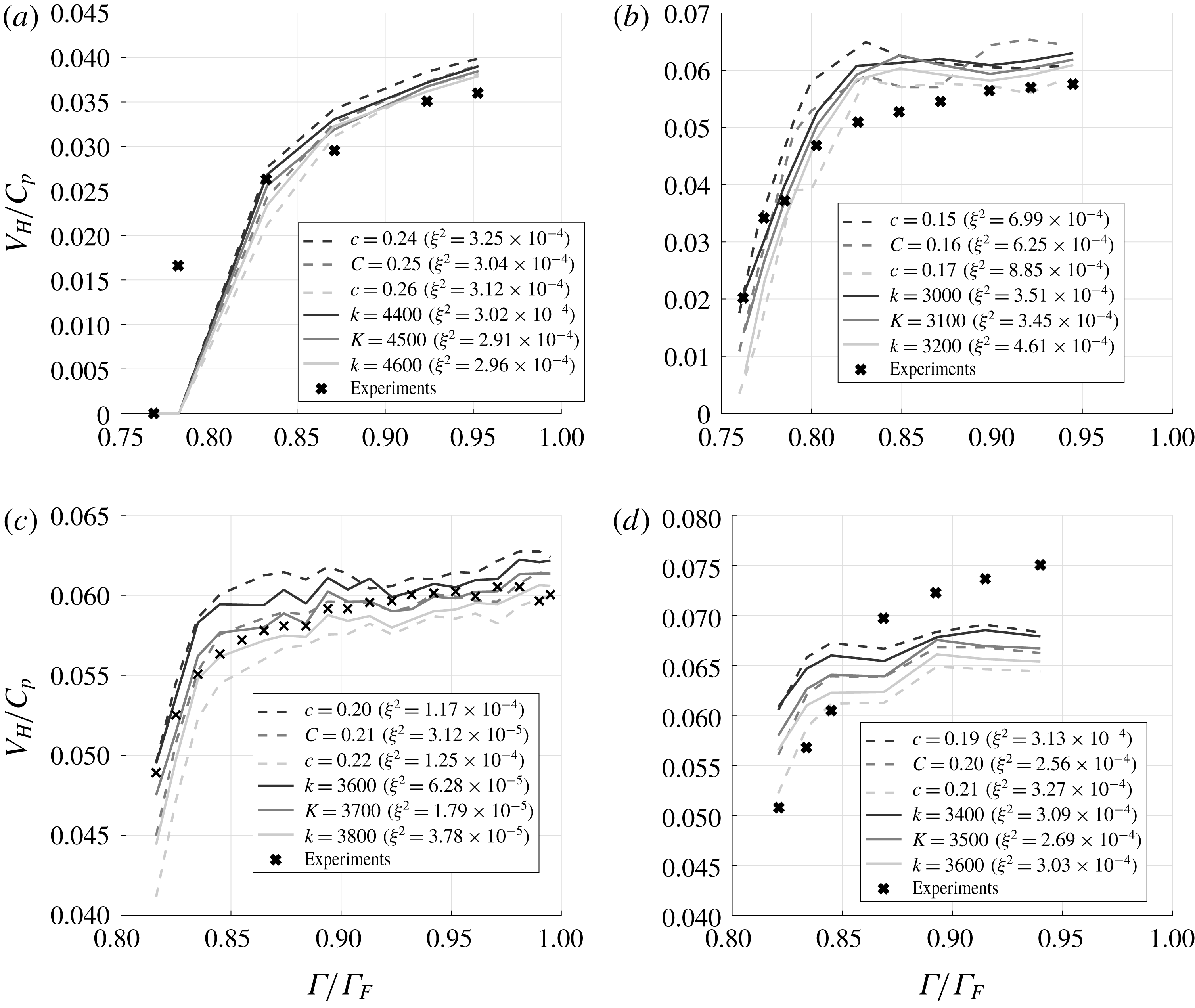
To find the optimal value
 $K$
of the proportionality constant
 $k$
for each droplet size (i.e.
 $\unicode[STIX]{x1D6FA}$
) for which the walking speed was reported at different driving accelerations in the experimental works, we test a sequence of values of
 $k$
. For each tested
 $k$
we find the differences
 $\unicode[STIX]{x1D709}_{i}$
between the experimental report for horizontal speed
 $u_{i}^{e}$
and the average horizontal speed as calculated from the simulations
 $u_{i}^{s}$
, where the
 $i$
th experimental point corresponds to a given value of
 $\unicode[STIX]{x1D6E4}_{i}/\unicode[STIX]{x1D6E4}_{F}$
(see figure 5). We thus define the total squared error for each attempted value of the drag parameter
 $k$
as
 $$\begin{eqnarray}\displaystyle \unicode[STIX]{x1D709}^{2}(k,\unicode[STIX]{x1D6FA})=\mathop{\sum }_{i=1}^{n}\unicode[STIX]{x1D709}_{i}^{2}(k,\unicode[STIX]{x1D6FA},\unicode[STIX]{x1D6E4}_{i}/\unicode[STIX]{x1D6E4}_{F})=\mathop{\sum }_{i=1}^{n}(u_{i}^{e}-u_{i}^{s})^{2}(k,\unicode[STIX]{x1D6FA},\unicode[STIX]{x1D6E4}_{i}/\unicode[STIX]{x1D6E4}_{F}), & & \displaystyle\end{eqnarray}$$
and we define
 $$\begin{eqnarray}\displaystyle K(\unicode[STIX]{x1D6FA})=\text{argmin}\,\unicode[STIX]{x1D709}^{2}(\cdot ,\unicode[STIX]{x1D6FA}). & & \displaystyle\end{eqnarray}$$
Walker speed as a function of
 $\unicode[STIX]{x1D6E4}$
for different values of the drag parameter
 $k$
, normalised by Faraday wave phase velocity (
 $C_{p}=19~\text{cm}~\text{s}^{-1}$
in experiments, and
 $C_{p}=19.88~\text{cm}~\text{s}^{-1}$
in simulations): (a)
 $\unicode[STIX]{x1D6FA}=0.7$
, (b)
 $\unicode[STIX]{x1D6FA}=0.8$
, (c)
 $\unicode[STIX]{x1D6FA}=0.83$
, (d)
 $\unicode[STIX]{x1D6FA}=0.86$
. Dashed lines correspond to the skidding friction model presented in Moláček & Bush (Reference Moláček and Bush2013b
), solid lines correspond to the skidding friction model developed in the present work. Experimental data for (a), (b) and (d) were obtained from Moláček & Bush (Reference Moláček and Bush2013b
), and data for (c) from Pucci et al. (Reference Pucci, Sáenz, Faria and Bush2016)

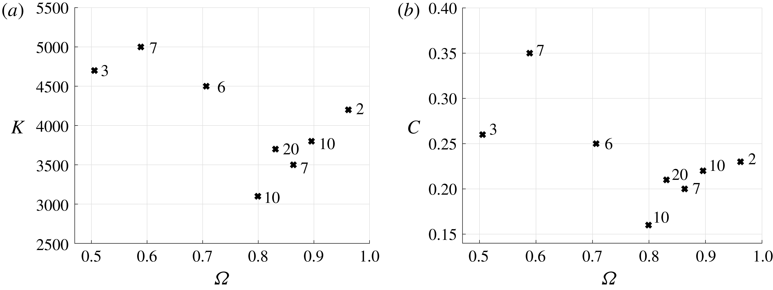
The values of
 $K(\unicode[STIX]{x1D6FA})$
are identified up to two significant figures and are reported in figure 5. Figure 6(a) shows the distribution of
 $K(\unicode[STIX]{x1D6FA})$
. We perform an entirely analogous calculation, using the friction model presented in Moláček & Bush (Reference Moláček and Bush2013b
), in which
 $F_{D}=-c\sqrt{\unicode[STIX]{x1D70C}R_{o}/\unicode[STIX]{x1D70E}}\,F(t)\boldsymbol{X}_{t}$
, and we obtain a similar distribution of values for the corresponding optimal proportionality constant
 $C(\unicode[STIX]{x1D6FA})$
. The respective walking speed predictions are reported in dashed lines in figure 5 and the distribution of
 $C(\unicode[STIX]{x1D6FA})$
is presented in figure 6(b). In practice, the value of
 $C$
used in different models ranges from
 $0.1$
to
 $0.35$
, as can be seen in the literature (Moláček & Bush Reference Moláček and Bush2013b
; Oza et al.
Reference Oza, Rosales and Bush2013; Milewski et al.
Reference Milewski, Galeano-Rios, Nachbin and Bush2015; Durey & Milewski Reference Durey and Milewski2017).
The agreement between theory and experiment shown in figure 5 is overall good, especially when considering the simplifications introduced; however, there clearly is room for improvement. The choice to stop at two significant figures in determining
 $K$
is based on the fact that the two neighbouring values at that precision provide an obvious bound to how much the predictions can be improved by a more precise value of
 $K$
, which indicate that no qualitative agreement is likely to be gained. A more complete understanding of the air flow in the intervening air layer would enable the production of better reduced models, as it would allow for a realistic treatment of the dependence of the
 $\bar{k}$
scaling factor on time or pressure distribution, and also of the time-varying air layer width
 $e$
. As part of our ongoing work, we have posed the problem including a coupled lubrication theory equation which we will attempt to address once we have successfully incorporated droplet deformations.
The skidding friction parameter
 $k$
is
 $O(10^{3})$
and
 $|A^{a}(t)|/(\unicode[STIX]{x03C0}R_{0}^{2})$
(i.e. the fraction of the droplet’s ‘shadow’ that is pressed) is
 $O(10^{-1})$
. Therefore
 $k|A^{a}(t)|/(\unicode[STIX]{x03C0}R_{0}^{2})$
is of order
 $O(10^{2})$
, which is significantly larger than
 $6$
(the factor that corresponds to Stokes’ drag). This verifies the intuition suggested at the end of § 2.4.1. Moreover, the value of
 $1/Ma$
(the reciprocal of the dimensionless mass of the droplet) ranges from
 $425$
(biggest walking droplets) to
 $1334$
(smallest walking droplets). This is consistent with walking droplet motion being dominated by the forces exerted by the waves onto the droplets, and also with bigger droplets, such as the superwalker considered in § 4.1 (for which
 $1/Ma=93$
), being less prone to walking under single-frequency forcing.
Skidding friction coefficients for the two models here considered. Panel (a) shows
 $K(\unicode[STIX]{x1D6FA})$
for the proposed model, and panel (b) shows
 $C(\unicode[STIX]{x1D6FA})$
for the model in Moláček & Bush (Reference Moláček and Bush2013b
). Numbers alongside the markers indicate the number of data points available in the literature for a given droplet size.

The similarity between figures 6(a) and 6(b) is consistent with the finding of the approximate proportionality between vertical force and pressed area reported in Galeano-Rios et al. (Reference Galeano-Rios, Milewski and Vanden-Broeck2017). We note that our proposed skidding friction model produces less total errors (
 $\unicode[STIX]{x1D709}^{2}(K(\unicode[STIX]{x1D6FA}),\unicode[STIX]{x1D6FA})$
) for most values of
 $\unicode[STIX]{x1D6FA}$
and that the relative deviation with respect to the mean value is smaller for
 $K$
(
 $\unicode[STIX]{x1D70E}_{d}(K)/\bar{K}=0.16$
,
 $\unicode[STIX]{x1D70E}_{d}(C)/\bar{C}=0.24$
). In what follows, we use
 $K(\unicode[STIX]{x1D6FA})$
for each droplet radius.
4 Comparisons to experiments of walking and bouncing droplets
Our model is completed with the specification of the skidding friction parameter. We thus proceed to simulate various experiments reported in the literature, across a range of physical parameters (
 $\unicode[STIX]{x1D6E4}$
,
 $\unicode[STIX]{x1D6FA}$
). In particular, we compare the many walking and bouncing states observed and the details of the wave field and impact phases.
We vary
 $\unicode[STIX]{x1D6FA}$
over the range of values typically used in experiments and with the driving amplitude
 $\unicode[STIX]{x1D6E4}$
ranging from bouncing threshold to Faraday threshold. We compare the resulting steady-state bouncers and walkers to the experimental results reported in Wind-Willassen et al. (Reference Wind-Willassen, Moláek, Harris and Bush2013). The results are summarised in figure 7, where squares (bouncers) and circles (walkers) indicate experimental reports and the background corresponds to our simulation results. The colour coding is shared between squares, circles and background. The red curve encloses the region in which the droplets walk in simulations and the vertical yellow dashed line indicates
 $\unicode[STIX]{x1D6E4}=1$
, to the right of which the driving acceleration reverses the sign of gravity (in the frame of reference of the bath) during part of the cycle. The hatched region describes
 $(2,2)^{2}$
bouncers (which could easily be mistaken for
 $(2,1)$
bouncers) as was reported in Galeano-Rios et al. (Reference Galeano-Rios, Milewski and Vanden-Broeck2017) and observed experimentally by Couchman, Turton & Bush (Reference Couchman, Turton and Bush2019).
Phase diagram for bouncing and walking droplets. Symbols indicate experimental reports of the modes of bouncing (Wind-Willassen et al.
Reference Wind-Willassen, Moláek, Harris and Bush2013); background colouring corresponds to the bouncing mode found in our simulations. The bouncing mode colour coding is the same for symbols and background. The leftmost region (red) indicates the range of
 $\unicode[STIX]{x1D6E4}$
for which our droplets are always in contact with the bath, and the vertical yellow dashed line indicates
 $\unicode[STIX]{x1D6E4}=1$
. The red curve encloses the region in which the droplets walk in simulations. Grey regions correspond to
 $(4,2)$
modes, light grey to
 $(4,2)^{1}$
and dark grey to
 $(4,2)^{2}$
; chaotic bouncing is shown in black. The six
 $\star$
markers indicate the bouncing and walking modes shown in figure 8. The hatched region corresponds to
 $(2,2)^{2}$
modes, which in Wind-Willassen et al. (Reference Wind-Willassen, Moláek, Harris and Bush2013) were classified as
 $(2,1)$
, but were later revealed by Damiano (Reference Damiano2015) to be less obvious instances of a
 $(2,2)$
mode (see figures 8
a and 8
b for details).

Variants of the same
 $(m,n)$
mode. Solid black lines depict the height of the south pole of the droplet, dashed black lines indicate the point on the free surface that is directly below the south pole; all with respect to an inertial observer in the laboratory. Grey lines correspond to the vertical force on the droplet
 $F_{\uparrow }$
. (a) The
 $(2,2)^{1}$
mode, in which the droplet reverses the direction of its vertical motion during both impacts. (b) The
 $(2,2)^{2}$
mode, in which the droplet reverses its vertical direction of motion every other impact. (c) The
 $(2,1)^{1}$
mode, in which the vertical force has two clearly marked maxima. (d) The
 $(2,1)^{2}$
mode, in which the vertical force shows a single peak. (e) The
 $(4,2)^{1}$
mode, which arises as a period-doubling bifurcation from the
 $(2,1)^{1}$
mode with all bounces producing vertical forces with two clear peaks but consecutive bounces have different force profiles. (f) The
 $(4,2)^{2}$
mode, which results from a period-doubling bifurcation of the
 $(2,1)^{2}$
mode.

We note that, in figure 7, the comparison to experimental results is excellent, with the exception of cases for which even the experimental distinction of bouncing modes is challenging. In particular, the agreement with experimental results is substantially improved with respect to the most detailed walking droplet model that was previously available (see figure 4 in Milewski et al. (Reference Milewski, Galeano-Rios, Nachbin and Bush2015)). These improved walker predictions are obtained whilst also doing away with three parameters and solving realistic and detailed impact dynamics. Furthermore, this model is also able to capture all bouncing droplet phenomena reported in figure 10 of Galeano-Rios et al. (Reference Galeano-Rios, Milewski and Vanden-Broeck2017), with improved accuracy.
Figure 8 shows the three observed instances in which we distinguish two kinds of bouncing modes that are characterised by the same
 $(m,n)$
notation. Figures 8(a) and 8(b) show two qualitatively different
 $(2,2)$
modes. We refer to the mode in panel (a) as the
 $(2,2)^{1}$
mode, in which the vertical motion of the droplet actually reverses direction four times over a period of motion, and to the one in panel (b) as the
 $(2,2)^{2}$
mode, in which reversals only take place twice over a motion period. Figures 8(c) and 8(d) reveal the qualitative differences between the
 $(2,1)^{1}$
and
 $(2,1)^{2}$
modes; the clearest distinction between the two being given by the fact that in the
 $(2,1)^{1}$
mode (panel c) there are two maxima in the vertical force over a relatively long (
 ${\approx}T_{f}$
) contact, whereas in the
 $(2,1)^{2}$
mode (panel d) a single maximum in vertical force is attained. Finally, we are also able to distinguish a
 $(4,2)^{1}$
mode (figure 8
e) and a
 $(4,2)^{2}$
mode (figure 8
f), which result from period-doubling bifurcations of the
 $(2,1)^{1}$
and
 $(2,1)^{2}$
modes, respectively. Moreover, the comparison between panels (b) and (c) illustrates the reason why
 $(2,2)^{2}$
bouncers can easily be mistaken for
 $(2,1)^{1}$
bouncers. In fact, the hatched region in figure 7 mostly coincides with experimental reports of
 $(2,1)^{1}$
modes. However, a more detailed report in Damiano (Reference Damiano2015) shows that, for
 $\unicode[STIX]{x1D6FA}=0.8$
, the bouncers in the hatched regions actually correspond to the gradual shrinking of the interval between the two bounces, as described below.
Evolution of the touch-down and take-off times as a function of the driving acceleration amplitude (
 $\unicode[STIX]{x1D6FA}=0.8$
). The shaded regions indicate the experimental report in Damiano (Reference Damiano2015), of the start (dark) and end (light) of droplet contacts. The vertical width of each region corresponds to the experimental uncertainty in the measurements (A. P. Damiano, 2015, personal communication). The corresponding simulation results for impact and take-off times are shown in black and grey lines, respectively. The vertical lines indicate the transition to a different
 $(m,n)$
mode in experiment (solid) and simulations (dashed).

Figure 9 shows the dependence of impact and lift-off times for driving accelerations ranging from the bouncing threshold to Faraday threshold. Along every vertical traverse, we can see the transitions undergone over a bouncing period, at a given
 $\unicode[STIX]{x1D6E4}/\unicode[STIX]{x1D6E4}_{F}$
. The left end of the graph shows how a weak driving acceleration leads to longer contacts, which, for low enough
 $\unicode[STIX]{x1D6E4}$
, end up merging and causing the droplet to stay attached to the surface. In reality, coalescence would occur in the vicinity of the left end of the graph; however, since we do not model the thin air layer dynamics in this work, we are not able to predict it accurately. As we move to the right in the graph, we can see first the
 $(1,1)$
mode (between
 $\unicode[STIX]{x1D6E4}/\unicode[STIX]{x1D6E4}_{F}\approx 0.23$
and
 $\unicode[STIX]{x1D6E4}/\unicode[STIX]{x1D6E4}_{F}\approx 0.42$
in the experiments, and between
 $\unicode[STIX]{x1D6E4}/\unicode[STIX]{x1D6E4}_{F}\approx 0.17$
and
 $\unicode[STIX]{x1D6E4}/\unicode[STIX]{x1D6E4}_{F}\approx 0.49$
in the simulations), for which both contacts are identical except for a shift in time of one forcing period. The period-doubling mechanism from the
 $(1,1)$
mode into the
 $(2,2)$
mode is evidenced in the middle section of figure 9, where we see that consecutive contacts start to differ from each other. As
 $\unicode[STIX]{x1D6E4}$
is increased further, the two contacts grow closer, finally merging into one long contact with two peaks in force (see figure 8
c) that are inherited from each one of the two distinct bounces in the
 $(2,2)$
mode. Further to the right of the graph, the contact time shortens and the force peaks fuse into a shorter pulse (see figure 8
d) that takes place roughly during the same interval of time for which contact took place in the
 $(1,1)$
mode, but in a period-doubled state. For insight on how driving acceleration influences walking velocity through changes in the vertical dynamics, figure 9 should be read alongside figure 5(b).
Comparison of wave field predictions to experimental measurements reported in Damiano et al. (Reference Damiano, Brun, Harris, Galeano-Rios and Bush2016). The wave field corresponds to a bouncer in the
 $(2,1)^{1}$
mode,
 $\unicode[STIX]{x1D6FA}=0.8$
and
 $\unicode[STIX]{x1D6E4}/\unicode[STIX]{x1D6E4}_{F}=0.75$
.

A comparison between surface topography measurements (Damiano et al.
Reference Damiano, Brun, Harris, Galeano-Rios and Bush2016) and our current wave field predictions is shown in figure 10. In this figure we observe a similar agreement to that reported in figure 12 in Galeano-Rios et al. (Reference Galeano-Rios, Milewski and Vanden-Broeck2017), where the impact was computed directly onto the perturbed surface and not decomposed into an impact onto a flat surface and the unforced wave field evolution. This suggests that the separation of the problem into two has not affected our wave field predictions significantly. The disagreement observed is mostly in the magnitude of the wave elevation in the near field of the droplet. We believe the disparity here is mainly due to the shortcomings of the quasi-potential fluid formulation. It is important to highlight that, with the current fluid model, the wavelength in experiments (
 ${\approx}4.75~\text{mm}$
, as reported by Pucci et al. (Reference Pucci, Sáenz, Faria and Bush2016)) is slightly different from that predicted by our fluid model (
 $=4.97~\text{mm}$
).
4.1 Superwalkers: two-frequency shaking
Valani et al. (Reference Valani, Slim and Simula2019) recently reported a new kind of walking droplets. These are relatively large droplets (up to 1.4 mm radius) that always bounce in place when the underlying bath is subject to simple harmonic motion, but walk particularly fast (up to approximately three times the maximum velocity for regular walkers, i.e.
 $C_{w}/C_{p}\approx 0.15$
) when the bath is subject to vertical oscillations obtained using the superposition of two sinusoidal signals of different frequencies. More specifically, this was observed to happen when the second frequency added is resonant with the subharmonic Faraday waves. The most relevant predecessor of this work is Sampara & Gilet (Reference Sampara and Gilet2016), who considered a combination of 80 and 64 Hz forcing in a bath of 20 cSt silicone oil, and were thus able to find a series of novel trajectories for the walking droplet system.
Valani et al. (Reference Valani, Slim and Simula2019) drive the oil bath with a vertical acceleration of the form
 $$\begin{eqnarray}\displaystyle z_{tt}=-g(\unicode[STIX]{x1D6E4}\cos (\unicode[STIX]{x1D714}_{o}t)+\unicode[STIX]{x1D6E4}^{1}\cos ({\textstyle \frac{1}{2}}\unicode[STIX]{x1D714}_{o}t+\unicode[STIX]{x1D703}_{1})), & & \displaystyle\end{eqnarray}$$
and therefore have two extra physical parameters with respect to the regular walking droplet experiment; namely, the subharmonic forcing amplitude, controlled by
 $\unicode[STIX]{x1D6E4}^{1}$
, and the phase shift between the two frequencies, given by
 $\unicode[STIX]{x1D703}_{1}$
. Regarding the bath motion, the two main differences between Sampara & Gilet (Reference Sampara and Gilet2016) and Valani et al. (Reference Valani, Slim and Simula2019) are the choice of the second frequency as resonant with the subharmonic Faraday waves and the introduction of the phase shift parameter, which was kept constant and equal to zero in Sampara & Gilet (Reference Sampara and Gilet2016). Moreover, the droplet size considered in Sampara & Gilet (Reference Sampara and Gilet2016) is in the regular walker size range. These differences explain why the superwalkers where not observed in their work.
The changes to the problem formulation, needed to model superwalkers, amount to replacing each instance of the expression
 $$\begin{eqnarray}\displaystyle {\displaystyle \frac{(1-\unicode[STIX]{x1D6E4}\cos (4\unicode[STIX]{x03C0}t))}{Fr}} & & \displaystyle\end{eqnarray}$$
in (3.2), (3.3), (3.10), (3.11) and (3.17) by
 $$\begin{eqnarray}\displaystyle {\displaystyle \frac{(1-\unicode[STIX]{x1D6E4}\cos (4\unicode[STIX]{x03C0}t)-\unicode[STIX]{x1D6E4}^{1}\cos (2\unicode[STIX]{x03C0}t+\unicode[STIX]{x1D703}_{1}))}{Fr}}, & & \displaystyle\end{eqnarray}$$
and selecting an appropriate value for the skidding friction constant
 $k$
. Another minor modification to simulate superwalkers is the use of a larger axisymmetric impact domain, i.e. a domain of radius
 $4\unicode[STIX]{x1D706}_{F}$
(twice the diameter of the one used for regular walkers). This choice was made to guarantee that waves triggered by large droplets, which sometimes produce contacts that are twice as long as those of walkers, do not reach the boundary of the axisymmetric domain before the impact is over.
We highlight that superwalking droplets undergo a non-negligible amount of deformation. In particular, one can see that the droplet’s Bond (
 $Bo_{d}=\unicode[STIX]{x1D70C}gR^{2}/\unicode[STIX]{x1D70E}$
) and Weber (
 $We_{d}=\unicode[STIX]{x1D70C}RV_{rel}^{2}/\unicode[STIX]{x1D70E}$
) numbers are larger that those for regular walkers, which indicates that deformations induced by gravity and inertia will be more prevalent. Typical physical parameters for a walking droplet yield
 $Bo_{d}=0.0671$
and
 $We_{d}=0.195$
, whereas for the superwalkers considered here
 $Bo_{d}=0.91$
and
 $We_{d}=0.261$
. Moreover, the ratio of walking speed
 $C_{w}$
to the relative vertical speed before impact
 $U_{z}$
is
 $C_{w}/U_{z}\approx 0.6$
. We therefore consider that the main motivation for the present section is to demonstrate the surprising extent to which a model based on a non-deforming droplet can capture (super)walking droplet phenomena.
Superwalkers at
 $\unicode[STIX]{x1D6FA}=1.91$
(
 $R_{o}=0.68~\text{mm}$
),
 $\unicode[STIX]{x1D6E4}/\unicode[STIX]{x1D6E4}_{F}=0.71$
and
 $\unicode[STIX]{x1D703}_{1}=8\unicode[STIX]{x03C0}/9$
. (a) Average velocity of superwalkers for different values of the drag parameter
 $k$
, normalised by the phase velocity of the Faraday wave of frequency 40 Hz (
 $C_{p}=19~\text{cm}~\text{s}^{-1}$
in experiments, and
 $C_{p}=19.88~\text{cm}~\text{s}^{-1}$
in the simulations). Vertical trajectories of the south pole (solid black lines) and of the free-surface point just underneath (dashed lines) are shown, together with vertical forces
 $F_{\uparrow }$
on droplets for different driving accelerations
 $\unicode[STIX]{x1D6E4}^{1}$
. Panels (b–f) show a droplet bouncing at single frequency forcing in the
 $(2,1)^{1}$
mode (b), walking in the
 $(2,1)^{1}$
mode (c), walking in the
 $(4,2)^{1}$
mode (d), walking in the
 $(2,1)^{2}$
mode (e), and walking in the
 $(4,2)^{2}$
mode (f). Experimental data in panel
 $(a)$
were obtained from Valani, Slim & Simula (Reference Valani, Slim and Simula2018).

In figure 3(a) of Valani et al. (Reference Valani, Slim and Simula2019), it is shown that superwalkers only appear in a window of the
 $\unicode[STIX]{x1D703}_{1}$
parameter that is centred roughly about
 $\unicode[STIX]{x1D703}_{1}=7\unicode[STIX]{x03C0}/9$
. Moreover, in figure 2(c) of Valani et al. (Reference Valani, Slim and Simula2018), the walking speed of a superwalker of
 $R_{o}=0.68~\text{mm}$
for fixed
 $\unicode[STIX]{x1D6E4}/\unicode[STIX]{x1D6E4}_{F}=0.71$
and
 $\unicode[STIX]{x1D703}_{1}=8\unicode[STIX]{x03C0}/9$
is reported as a function of
 $\unicode[STIX]{x1D6E4}^{1}/\unicode[STIX]{x1D6E4}_{F}^{1}$
, with
 $\unicode[STIX]{x1D6E4}_{F}^{1}$
given by the Faraday threshold for the fluid bath when driven at an angular frequency of
 $\unicode[STIX]{x1D714}_{o}/2$
. The superwalker phenomenon is reproduced for any value of the drag parameter
 $k$
in the order of the values chosen for
 $K(\unicode[STIX]{x1D6FA})$
(figure 6). That is to say, droplets bounce when in the presence of a single frequency and walk faster than typical walkers (up to more than twice as fast as the fastest walkers) when the second frequency is added to the driving. To find the optimal
 $K(\unicode[STIX]{x1D6FA})$
for
 $\unicode[STIX]{x1D6FA}(R_{o}=0.68)$
, we test different values of
 $k$
and find the one that minimises the squared error with respect to the experimental results reported in figure 2(c) of Valani et al. (Reference Valani, Slim and Simula2018).
Figure 11(a) shows the comparison between the experimental report of superwalker velocity (Valani et al.
Reference Valani, Slim and Simula2019) and our simulation results for values of
 $k$
in the vicinity of its optimal value
 $K(\unicode[STIX]{x1D6FA}=1.91)$
. Figures 11(b–f) show the modes of bouncing displayed and the forces on the droplet due to collisions with the bath. When in the presence of a single-frequency forcing (figure 11
b),
 $\unicode[STIX]{x1D6E4}_{1}=0$
; the droplet bounces in place displaying a
 $(2,1)^{1}$
mode with a particularly long contact. We note that our model shows in fact that the superwalkers are barely lifting off the surface when a single frequency is present. As the second frequency is introduced (figure 11
c–f), the droplet walks even for
 $\unicode[STIX]{x1D6E4}^{1}/\unicode[STIX]{x1D6E4}_{F}^{1}$
as low as
 $0.18$
(figures 11
a and 11
b). As in the case of the walkers, the mode of bouncing observed changes with the driving acceleration (
 $\unicode[STIX]{x1D6E4}^{1}$
, in this case). In figure 11, we see the superwalkers bifurcation sequence:
 $(2,1)^{1}\rightarrow (4,2)^{1}\rightarrow (2,1)^{2}\rightarrow (4,2)^{2}$
. It is worth noting that, even though the skidding friction coefficient is of the same order as the one used for regular walkers, the walking speeds we obtain are in line with the superwalker experiments (up to three times the speed of single-frequency walkers).
We note that our model predicts that the superwalkers have a wave field that is qualitatively different from that of single-frequency walkers. As can be seen in figure 12(b), the wave field behind the superwalker does not exhibit, for these parameters, the typical interference pattern reported by Eddi et al. (Reference Eddi, Sultan, Moukhtar, Fort, Rossi and Couder2011), also observable in figure 4(b). Experimental reports from Valani et al. (Reference Valani, Slim and Simula2019) show that the wave field of the superwalkers indeed looks like our predictions. This distinctive wave field is likely due to the fact that we are exciting Faraday waves under two-frequency forcing, which will respond to a Mathieu equation that is different from the one for single-frequency forcing found by Benjamin & Ursell (Reference Benjamin and Ursell1954); see Zhang & Vinals (Reference Zhang and Vinals1997). In particular, the Fourier transform of the wave field contains a higher contribution of wavelengths in the range of the Faraday wavelength for 40 Hz forcing (
 $k\approx 7.16~\text{cm}^{-1}$
). Moreover, the wave field associated with such a large droplet deforms the free surface substantially in the vicinity of the droplet, as can also be seen in figures 11(b–f), even in the absence of a second forcing frequency (figures 11
b and 12
a). We highlight that the inset plots in figures 12
 $(c)$
and 12
 $(d)$
show that the surface remains smooth at the impact location. This can also be appreciated in the corresponding animation of the simulations results from the cases in figure 12, which are provided as supplementary movies.
Wave field predictions for
 $\unicode[STIX]{x1D6FA}=1.91$
,
 $\unicode[STIX]{x1D6E4}/\unicode[STIX]{x1D6E4}_{F}=0.71$
and
 $\unicode[STIX]{x1D703}_{1}=8\unicode[STIX]{x03C0}/9$
. (a) Bouncer at
 $\unicode[STIX]{x1D6E4}^{1}/\unicode[STIX]{x1D6E4}_{F}^{1}=0$
, and (b) superwalker moving to the right at
 $\unicode[STIX]{x1D6E4}^{1}/\unicode[STIX]{x1D6E4}_{F}^{1}=0.87$
. Panels
 $(c)$
and
 $(d)$
show cross-sections of the wave field represented in
 $(a)$
and
 $(b)$
, respectively. The wave fields in panels (a–c) and
 $(d)$
are sampled at the time at which the maximum surface deflection (in absolute value) occurs while the droplet is located at
 $\boldsymbol{X}(t)=(0,0)$
. Inset plots in panels
 $(c)$
and
 $(d)$
show the impact location using the same scale for the vertical and horizontal axes (units of
 $\unicode[STIX]{x1D706}_{F}$
). Panels
 $(e)$
and
 $(f)$
show the respective analogous cross-sections to
 $(c)$
and
 $(d)$
; though taken just before a droplet impact. Animations of the wave field and droplet motion for these two simulations are included as supplementary movies.

To the best of our knowledge, no other model has captured superwalker phenomena. In particular, we attempted to use the model presented in Milewski et al. (Reference Milewski, Galeano-Rios, Nachbin and Bush2015) and obtained a significant mismatch in the vertical dynamics.
The superwalker phenomenon is one more piece of evidence for the extremely rich dynamics associated with the bouncing droplet system. A more complete treatment of superwalkers requires the consideration of droplet deformation and will be the subject of future work.
5 Discussion
We have described a general methodology to study impacts and rebounds at capillary scale. The method relies on the assumption that the impacting object does not become immersed and that we have a theory for the evolution of the capillary contact angle. When we apply the methodology to Faraday walkers, after a series of approximations, we arrive at a walker model that combines a quasi-potential fluid model with the superposition of translated axisymmetric impacts. We obtain a highly realistic walking droplet model that solves repeated bounces with minimal assumptions on the nature of the impact. The use of few assumptions enables the generation of a great number of detailed predictions for the physical system. We carefully compare these predictions to experimental reports available in the literature, obtaining an overall remarkable agreement.
We highlight the fact that our system is able to capture extremely well the majority of phenomena tested here. This is a strong indication that droplet deformation plays a relatively minor role in the overall dynamics of the walking droplet system, except possibly for superwalkers, for which our walking speed predictions deviate slightly more from the experimental reports. These deviations from our predictions are not unexpected, as droplet deformation is known to be non-negligible in this case. An adaptation of the kinematic match method which couples the deformation of the impacting droplet to the fluid equations is under way; its implementation should result in a substantial improvement to our superwalker predictions and it should provide the tools to assess precisely the extent to which the results change when the impacting object is compliant. To account for inertial effects in droplet deformation during impact, we need to approximate the fluid flow inside the droplet. Moreover, the decomposition of the impact into vertical and horizontal motion, though in principle still possible, requires the observation of some additional effects (Purvis & Smith Reference Purvis and Smith2005).
Single bounce dynamics, similar to those observed in bouncing droplets, have been obtained for solid spheres (see e.g. Lee & Kim Reference Lee and Kim2008); however, sustained periodic bouncing and walking regimes have not been reproduced with solids. Surface roughness of solids at the scale of the air layer width, which can puncture the lubrication layer, could be the cause. It is also possible that deformation plays a role in preserving the integrity of the air layer; nevertheless, our present work strongly suggests that the role of these deformations is otherwise relatively minor in terms of the overall dynamic behaviour for the parameter regime considered here (see for instance figure 9). Moreover, droplet deformations have been shown to play an important role when the fluid of the bath is significantly less compliant than that of the droplet (see Terwagne et al. Reference Terwagne, Ludewig, Vandewalle and Dorbolo2013). Such a system can also be studied using a kinematic match method for deformable impactors. Deformation in bouncing, walking and superwalking droplets will be the subject of a separate study, which will also consider more general two-frequency forcing bouncing droplet systems, including the system reported by Sampara & Gilet (Reference Sampara and Gilet2016). This future work will allow us to quantify dynamic droplet deformation and can be compared to experimental measurements of droplet deformation reported by Couchman et al. (Reference Couchman, Turton and Bush2019), indicating at most a 5 % radial deformation for single-frequency walkers. Similarly, in a private communication with the lead author of Valani et al. (Reference Valani, Slim and Simula2019), it was reported that superwalkers of the size considered here show a radial deformation of at most 9 %.
Our work reinforces the well-established notion that translating axisymmetric impacts provides a sufficiently good approximation when modelling walkers. This is also in agreement with the more general notion that the horizontal component of impact velocity has a negligible role in solid-impact problems unless it is significantly large (see e.g. Moore et al. Reference Moore, Howison, Ockendon and Oliver2012), which is one of Trefethen’s paradoxes (Trefethen & Panton Reference Trefethen and Panton1990). Moreover, we make use of the linear nature of the waves in this problem to decompose its solution into two parts, which introduces the possibility of using different methods to solve the impact and the wave evolution. One can then use the optimal method for each part and arrive more efficiently at a more accurate solution to the full problem, once they are combined. Consequently, in this work, we solve bouncers and walkers in less than half the computation time required for the bouncer-only simulations in Galeano-Rios et al. (Reference Galeano-Rios, Milewski and Vanden-Broeck2017) and at four times increased spatial accuracy. Another important consequence of successfully separating the problem into two is that this allows for the possibility of solving the unforced waves with other, perhaps more elaborate, fluid models which might be solved very efficiently when unforced by surface pressures but with which it would prove challenging to solve numerous impacts.
Many walking droplet experiments involve complex interactions between the impact phase and the droplet trajectory. This is expected to be the case in confined chaotic motion in a potential (Perrard et al. Reference Perrard, Labousse, Miskin, Fort and Couder2014; Durey, Milewski & Bush Reference Durey, Milewski and Bush2018) or in a corral (Harris et al. Reference Harris, Moukhtar, Fort, Couder and Bush2013). For long-time realistic computations of such problems, where the impacts may vary chaotically, we could accelerate simulations by pre-computing a library of droplet impacts with the surface, i.e. a database of axisymmetric solutions parametrised by relative impact velocity and impact phase, from which the resultant wave field and droplet forces can be recalled, the droplet trajectory calculated, and the new wave field superposed onto the pre-existing wave field. This approach is currently being developed to realistically introduce the effect of impact phase variations in two-dimensional models of tunnelling and two-particle correlations, such as those in Nachbin, Milewski & Bush (Reference Nachbin, Milewski and Bush2017) and Nachbin (Reference Nachbin2018).
Detailed wave field predictions have proven to be fundamental to capture droplet–droplet interactions, as the role of moving wavefronts and subtle changes in impact phases define the direction of the horizontal forces on the droplets bouncing in close range (Galeano-Rios et al. Reference Galeano-Rios, Couchman, Caldairou and Bush2018). The next-order approximation for the fluid motion in the bath is given by the linearised Navier–Stokes equations for incompressible flow (Galeano-Rios Reference Galeano-Rios2016; Durey Reference Durey2018; Tadrist et al. Reference Tadrist, Shim, Gilet and Schlagheck2018), which are non-local in time (Prosperetti Reference Prosperetti1976; Beyer & Friedrich Reference Beyer and Friedrich1995). In view of our present results, it seems clear that a combination of the solution of the linearised Navier–Stokes equations with a library of impacts is likely the most adequate approach to study multi-droplet systems in great detail.
Multi-droplet systems are a subject of particular interest, as they are a realisation of an active matter system in which the ‘agents’ take energy from the waves and also interact through them. Moreover, other collections of surface-bounded objects would provide similar examples of wave-mediated active matter systems which can be modelled with relatively simple modifications of the methods presented here.
Acknowledgements
C.A.G.-R. and P.A.M. gratefully acknowledge the support of EPSRC project EP/N018176/1. J.-M.V.-B. gratefully acknowledges the support of EPSRC project EP/NO18559/1. We also thank A. Damiano and R. Valani for sharing details of their experimental measurements.
Supplementary movies
Supplementary movies are available at https://doi.org/10.1017/jfm.2019.409.
Appendix A. Physical constants
Air:
 $$\begin{eqnarray}\displaystyle \unicode[STIX]{x1D707}_{air}=1.8\times 10^{-4}~\text{g}~\text{cm}^{-1}~\text{s}^{-1}. & & \displaystyle\end{eqnarray}$$
Silicone oil:
 $$\begin{eqnarray}\displaystyle & \displaystyle \unicode[STIX]{x1D70E}=20.6~\text{dyne}~\text{cm}^{-1}, & \displaystyle\end{eqnarray}$$
 $$\begin{eqnarray}\displaystyle & \displaystyle \unicode[STIX]{x1D70C}=0.949~\text{g}~\text{cm}^{-3}, & \displaystyle\end{eqnarray}$$
 $$\begin{eqnarray}\displaystyle & \displaystyle \unicode[STIX]{x1D708}=\unicode[STIX]{x1D707}/\unicode[STIX]{x1D70C}=0.2~St=0.2~\text{cm}^{2}~\text{s}^{-1}. & \displaystyle\end{eqnarray}$$
Gravity in the frame of reference of the bath:
 $$\begin{eqnarray}\displaystyle & \displaystyle g=980~\text{cm}~\text{s}^{-2}, & \displaystyle\end{eqnarray}$$
 $$\begin{eqnarray}\displaystyle & \displaystyle \unicode[STIX]{x1D6E4}_{F}=4.22g=4135~\text{cm}~\text{s}^{-2}, & \displaystyle\end{eqnarray}$$
 $$\begin{eqnarray}\displaystyle & \displaystyle \unicode[STIX]{x1D6E4}_{F}^{1}=1.19g=1166~\text{cm}~\text{s}^{-2}, & \displaystyle\end{eqnarray}$$
 $$\begin{eqnarray}\displaystyle & \displaystyle \unicode[STIX]{x1D714}_{o}=2\unicode[STIX]{x03C0}\times 80~\text{rad}~\text{s}^{-1}. & \displaystyle\end{eqnarray}$$