

I. INTRODUCTION
Wireless power transfer (WPT) is widely used in many fields due to its superiority on convenient transmission, flexibility on charging devices, and efficiency during power charging [Reference Badr, Robert, Paul, Delaney and Nikolai1–Reference Narayanamoorthi, Juliet and Chokkalingam7]. As we know, WPT technology can be divided into fixed charging methods [Reference Campi, Cruciani, Santis, Maradei and Feliziani3, Reference Barmada, Dionigi, Mezzanotte and Tucci5] and moveable [Reference Badr, Robert, Paul, Delaney and Nikolai1, Reference Basar, Ahmad, Cho and Ibrahim2, Reference Zhang, Lin and Hui4, Reference Bocan, Mickle and Sejdic6, Reference Madhja, Nikoletseas and Voudouris8] charging methods according to the application scenario. At present, the development of fixed charging methods is relatively mature. However, with the wide application of WPT, especially in the field of mobile devices such as electric vehicles [Reference Mohamed, Berzoy and Mohammed9–Reference Zhang, Chen, He, Zhao, Lu and Yuan10] and medical implants [Reference Nie and Yang11–Reference Liu, Zhang, Hackworth, Sclabassi and Sun13] in operation, the conventional fixed charging can no longer meet the needs of charging when the relative position of the transmitting coils and receiving coils changes. Therefore, there is a strong demand for the development of the moveable wireless charging technology.
Several types of WPT techniques for mechanical systems with movable mechanical parts have been reported recently [Reference Mohamed, Berzoy and Mohammed9–Reference Zhang, Chen, He, Zhao, Lu and Yuan10, Reference Jinghui and Song14, Reference Liu, Yang, Jiang, Ruan and Chen15]. However, due to the moveable feature of transmission coils and receiving coils, the mutual inductance is always changing with different coil position and angular. Therefore, it is very important to have a good insight of the working principle of these kinds of moveable coils. It is also very important to evaluate the effective range of misalignment for moveable WPT systems.
At present, the analytical formulas of the mutual inductance between transmitting coils and receiving coils are mainly based on the Neumann's integral formula and the filament method. In [Reference Mohamed, Berzoy and Mohammed9, Reference Zhang, Chen, He, Zhao, Lu and Yuan10, Reference Jinghui and Song14], a calculation theory of changing mutual inductance between segmented-spiral transmitting coils and receiving plane-spiral coils based on Neumann's formula for electric vehicles is introduced. However, this calculation model can only be used for the plane coil with lateral misalignment. In paper [Reference Liu, Yang, Jiang, Ruan and Chen15], an equivalent analytical model of spatial misalignments between transmitting and receiving coils based on Neumann's formula is established. Three mutual inductance curves versus lateral, angular and general misalignment were achieved. However, it is mainly based on one turn circular coil model. A schematic diagram for the calculation of the mutual inductance between the bowl-shaped coil is reported in Ref. [Reference Kim, Kim, Kim and Park12]. It provides a calculation model for other shaped besides circular coils. In [Reference Zhang, Lin and Hui4], a ball-shaped joint is proposed for a wireless power transfer system, the calculation of the mutual inductance is also based on the Neumann's formula. However, the skin effect caused by high frequency current is not considered, so the calculation model is less precise.
In order to establish a more accurate mutual inductance calculation model, filament method is used for mutual inductance calculation between the coils with high frequency current. In this way, the current is subdivided into a plurality of current elements with equal size and negligible cross-sectional area, which can decrease or eliminate the calculation error caused by high-frequency current distribution. In [Reference Wu, He, Wang and Sun16–Reference Jiao, Liu and Zeng26], calculation of mutual inductance between transmitting coils and receiving coils based on the filament method was reported. The experimental results are compared with calculated results to certificate the calculation model of mutual inductance based on filament method is more precise. However, due to the complexity of mathematical derivation procedure, only plane circular and rectangular coils model are involved in those studies.
Considering those papers mentioned above, there is a lack of more precise calculation model of the mutual inductance for special shaped coils. Moreover, for those kinds of special shaped coils, how to optimize the winding structure and to determine the effective power transfer range of lateral or angular misalignment are still main challenges.
In this paper, a WPT system with a ball-shaped coil used for free-rotating robot joints is put forward. There are two main contributions in this paper.
• A calculation model based on filament method especially for ball-shaped coil is proposed. Coil section is subdivided to decrease the skin effect caused by high-frequency current to make the calculation results more precise. Calculation results of the mutual inductance are compared with the simulation results. The error is below 3%, which can verify the accuracy of the proposed calculation model.
• Based upon the proposed calculation model, a model with minimized changing rate of the mutual inductance is picked out. Therefore, an optimized design for the ball-shaped coils winding is achieved. Design procedure of the various diameter multi-winding coils are given in detail. Then, an experimental platform is built to verify the feasibility and stability of the WPT system.
This paper is organized as follows. In section II, a calculation model of the mutual inductance based on filament method is proposed and the optimized design of the ball-shaped coil is chosen out. The calculation results are compared with the simulation results by using software named Maxwell (3D). In section III, the power transfer efficiency and outpower of the series-series topology are analyzed. The optimized working frequency and load are determined. Experimental results, such as voltage and current across primary and secondary coils and curves are shown in section IV.
II. OPTIMAL DESIGN OF THE BALL-SHAPED COIL
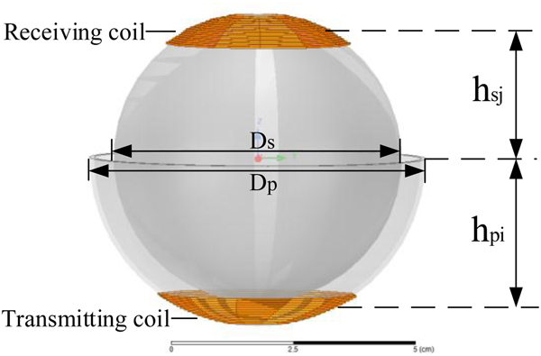
The ball-shaped joint is a type of synovial joint in which the ball-shaped surface of one rounded bone fits into the cup-like depression of another bone. As shown in Fig. 1, the primary and secondary coils are wound around the two ball-shafts respectively. The two ball-shafts represent the robot joints and they are coaxial in order to make sure that there is only an angular misalignment when the joints move. h pi refers to the distance between the center of no. i primary coil and the center of the coordinate system. h sj refers to the distance between the center of no. j secondary coil and the center of the coordinate system. The diameters of the transmitting and receiving ball are named D p and D s respectively. The D p is larger than D s in order to reserve a gap for joints moving and rotating.
Actual model of the coil winding.

A) Different coil winding methods
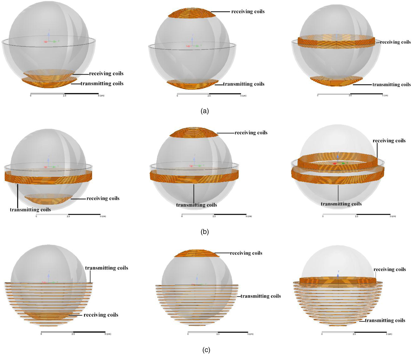
The hemisphere below is named transmitting ball, on which the coils are named primary coils. The sphere above is named receiving ball, on which the coils are named secondary coils. Assuming that the robot joint size has been determined, the diameter of the transmitting ball D p and receiving ball D s is 70 and 60 mm, respectively. Several coil winding combinations of the primary and secondary ball-shaft are shown in Fig. 2.
Several kinds of winding method for joints. (a) The combinations with the primary coil winding around lower part of the ball, from left to right are named P1S1, P1S2, P1S3. (b) The combinations with the primary coil winding around upper part of the ball, from left to right are named P2S1, P2S2, P2S3. (c) The combinations with the primary coil winding around the ball averagely, from left to right are named P3S1, P3S2, P3S3.

There are nine kinds of combination of the primary and secondary winding methods as shown in Fig. 2. The mutual inductance between primary and secondary coil will change as the angular misalignment. The model with the minimized change rate of the mutual inductance as the angular misalignment will be chosen as the optimized winding design of the joints.
B) Mutual inductance calculation
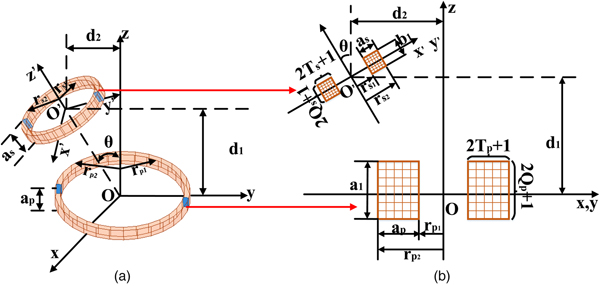
The mutual inductance calculation model of the ball-shaped coil is shown in Fig. 3. The variables involved in this model are the rotation angle of the secondary coil relative to the primary coil coordinate system and the radius of the primary and secondary coil.
Spatial mutual inductance model of rectangular cross section air-core circular coils. (a) Primary and secondary coil with angular misalignment. (b) Configuration of mesh matrix for rectangular cross section using filamentary methods.

Based on the Grover formulation, the mutual inductance between misalignment circular coils with rectangular cross can be calculated using filament method. But those papers fail to take the change of the coils radius into account. A mutual inductance calculation method for ball-shaped coil with change of coils radius based on filamentary method is proposed.
As shown in Fig. 3(a), the number of turns, inner diameter, outer diameter, and axial thickness of the primary coil and secondary coil are named N x, r x1, r x2, and a x respectively. Among them, x = p refers to primary coil, x = s refers to secondary coil. T p and Q s are the amount of the subdivision density. The section of transmitting coil is divided into (2T p + 1) × (2Q p + 1) elements, the section of receiving coil is divided into (2T s + 1) × (2Q s + 1) elements. The geometric center and the central axis of the primary coil coincide with the origin O and z axes of the coordinate system O xyz, respectively. The distance between the geometric center of the secondary coil and the plane xOy is d 1, and d 2 is the length from the geometric center of the secondary coil to z-axis. When h x is negligible relative to r x2–r x1, it can be equivalent to a thin-disk coil. In contrast, it can be equivalent to a thin-walled solenoid. When the axial and radial dimensions of the coil are negligible relative to the coil radius, it can be equivalent to a ring coil.
The current is distributed over the entire section when it passes through a coil having a certain cross section. Skin effect occurs when the current frequency is high, which will increase the calculation difficulty of mutual inductance. In order to make the calculation easier, it is necessary to assume that the current is evenly distributed over the cross section of the coil. Filament method, which is a method of subdividing current into negligible equal-sized and concentrated current elements of a subdivided section, can reduce or eliminate the influence of mutual inductance calculation error caused by current distribution.
As shown in Fig. 3(b), the section of the primary coil is divided into (2T p + 1) × (2Q p + 1) elements equally, the section of the secondary coil is divided into (2T s + 1) × (2Q s + 1) elements in the same way. Among them, T p, Q p, T s, and Q s represent the precision of the filament for primary and secondary coils respectively. N 1 and N 2 are the turns of the primary and secondary coils respectively. a, b, c, and d are the variables of the elements for filamented units. The mutual inductance of the inclined circular coil with angle misalignment and change of radius can be obtained in the following form:
 $$M = \displaystyle{{N_1N_2\sum\nolimits_{a = -Q_p}^{a = Q_p} {\sum\nolimits_{b = -T_p}^{b = T_p} {\sum\nolimits_{c = -T_s}^{c = T_s} {\sum\nolimits_{d = -Q_s}^{d = Q_s} {M(a,b,c,d)}}}}} \over {(2Q_p + 1)(2T_p + 1)(2T_s + 1)(2Q_s + 1)}}$$
where
 $$\eqalign{M(a{\rm,} b{\rm,} c{\rm,} d) &= \displaystyle{{\mu _0\sqrt {R_{pi}(b)R_{sj}(c)}} \over \pi} \cr& \quad \times \int_0^\pi {\displaystyle{{[{\rm cos}\theta -(y(p)/R_s(l))\,{\rm cos}\,\phi ]\psi (k)} \over {\sqrt {V^3}}}} d\phi} $$
In equation (2), μ 0 is the permeability of vacuum valued 4π × 10−7 H/m. The radius of primary coil element R pi(b) is:
 $$R_{pi}(b) = R_{pi} + \displaystyle{{a_p} \over {2T_p + 1}}b,\quad b = -T_p, \ldots, 0, \ldots, T_p$$
R pi will change as the height of the coil:
 $$R_{pi} = \displaystyle{{r_{p1i} + r_{p2i}} \over 2}$$
 $$r_{p2i} = \sqrt {D_p^2 -h_{pi}^2}, \quad i = 1,2, \ldots, N_p$$
 $$a_p = r_{p2i}-r_{p1i}$$
The radius of secondary coil element R sj(c) can be obtained in the same way:
 $$R_{sj}(c) = R_{sj} + \displaystyle{{a_s} \over {2T_s + 1}}c,\quad c = -T_s, \ldots, 0, \ldots, T_s$$
R sj will change as the height of the coil:
 $$R_{sj} = \displaystyle{{r_{s1j} + r_{s2j}} \over 2}$$
 $$r_{s2j} = \sqrt {D_s^2 -h_{sj}^2}, \quad j = 1,2, \ldots, N_s$$
 $$a_s = r_{s2j}-r_{s1j}$$
In equation (2), V is a volume containing the total magnetic energy in equation (2), It can be calculated as follows:
 $$V = \sqrt {1-{\cos} ^2\,\phi {\sin} ^2\,\theta -2\displaystyle{{y(d)} \over {R_s}}\cos \,\phi \,\cos \,\theta + \displaystyle{{y^2(d)} \over {R^2_s}}} $$
 $$y(d) = d_2 + \displaystyle{{b_1\,\sin \,\theta} \over {2Q_s + 1}}d,\; \quad d = -Q_s, \ldots, Q_s$$
ψ(k) is the Legendre function of the second kind and half-integral degree. It can be calculated as follows:
 $$\psi (k) = \left( {\displaystyle{2 \over k}-k} \right)K(k)-\displaystyle{2 \over k}E(k)$$
where
 $$k^2 = \displaystyle{{4\lambda V} \over {{(1 + \lambda V)}^2 + \sigma ^2}}$$
 $$\sigma = \delta -\lambda \,\cos \,\phi \,\sin \,\theta $$
 $$\lambda = \displaystyle{{R_{si}} \over {R_p(b)}}$$
 $$\delta = \displaystyle{{z(a,d)} \over {R_p(b)}}$$
 $$\eqalign{z(a,d) &= d_1 + \displaystyle{{a_1} \over {2Q_p + 1}}a-\displaystyle{{b_1\,\cos \,\theta} \over {2Q_s + 1}}d,\cr a &= -Q_p, \ldots, Q_p}$$
K(k) and E(k) represent the first and second type elliptic integral respectively.
 $$K(k) = \int_0^{\pi /2} {\displaystyle{{d\varphi} \over {{(1-k^2\,{\rm sin}^2\,\varphi )}^{1/2}}}} $$
 $$E(k) = \int_0^{\pi /2} {{(1-k^2\,{\rm sin}^2\,\varphi )}^{1/2}d\varphi} $$
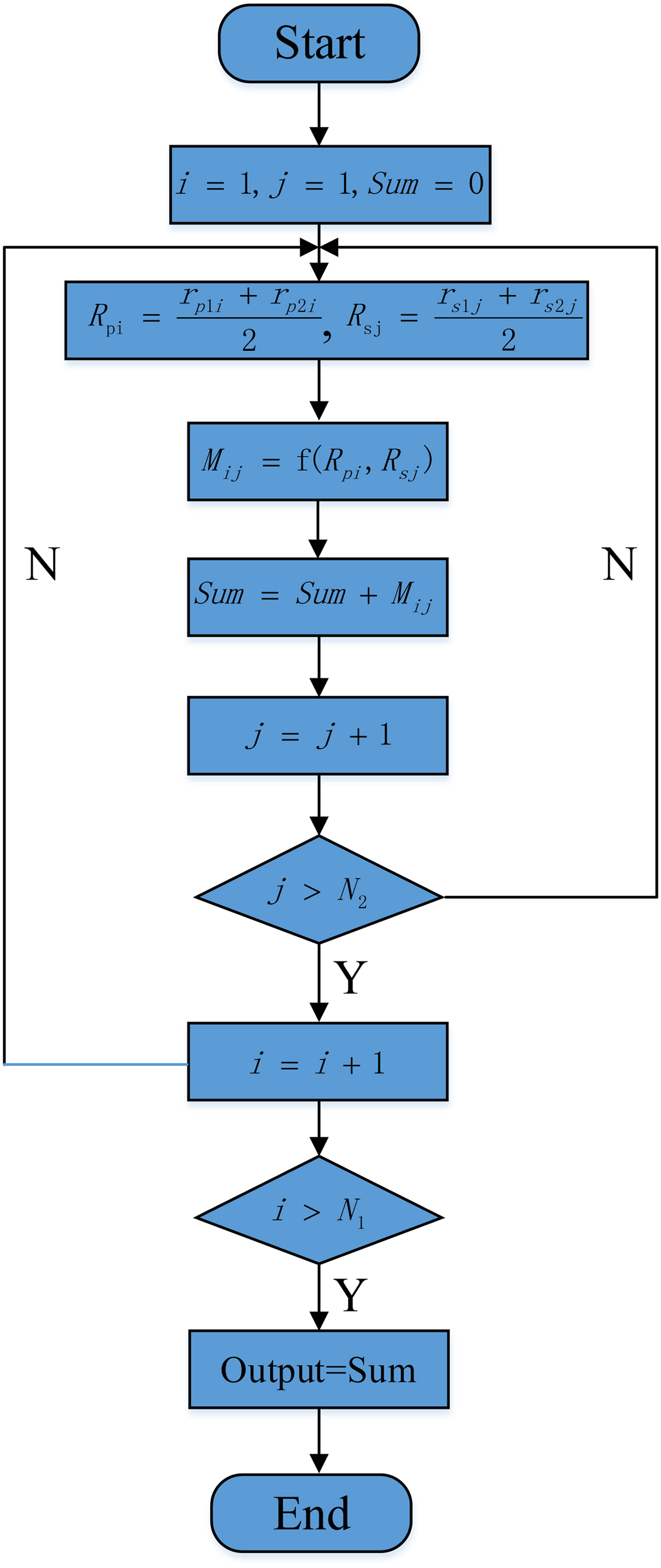
In order to demonstrate the mutual inductance calculation process based on the filament method for the moveable model clearly, the flow diagram is shown in Fig. 4.
The flow diagram of the calculation model based on the filament method.

As shown in Fig. 4, for the moveable ball-shaped coils, there is a change of radius of the coils at different height. So, the calculation is a superimposed process of each two coils.
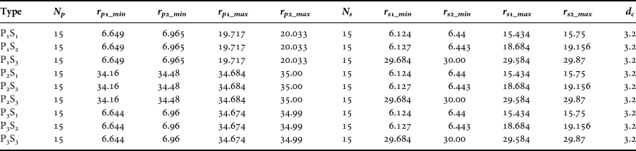
The specific parameters of each combination are shown in Table 1. Among these, d c represents the distance between two coils, N p and N s refer to the turns of the primary and secondary coils respectively. r p1_min and r p2_min represent the minimized inner and outer diameter of primary coil. r p1_max and r p2_max represent the maximized inner and outer diameter of primary coil. r s1_min and r s2_min represent the minimized inner and outer diameter of secondary coil. r s1_max and r s2_max represent the maximized inner and outer diameter of secondary coil.
The calculation parameters of the nine kinds of winding combination; unit: N (turns) r, d c (mm).

C) Comparison of the calculated and simulated mutual inductance
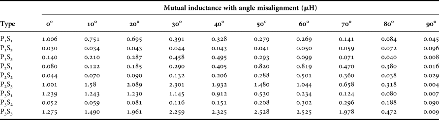
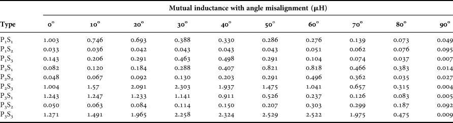
In order to verify the correctness of the calculation method in the previous section, the mutual inductance of those model mentioned above can be obtained by using an electromagnetic simulator (Maxwell 3D), the mutual inductance can be obtained by calculating and simulating as shown in Tables 2 and 3.
Mutual inductance of different models with angle misalignment by calculating.

Mutual inductance of different models with angle misalignment by simulating.

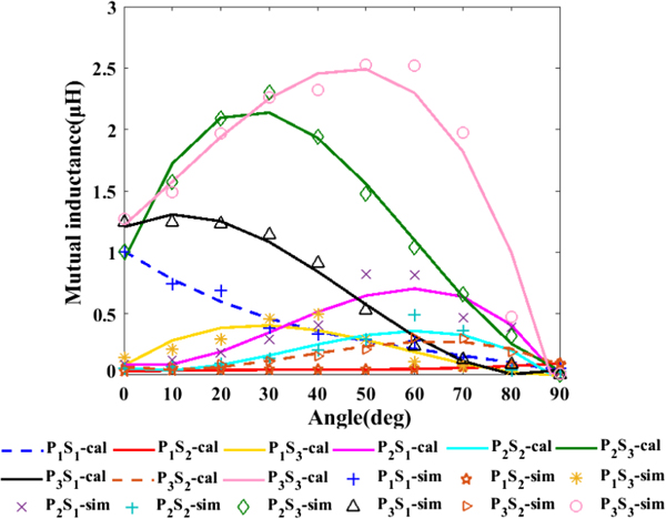
In order to show the value of the mutual inductance of the different kinds of model more clearly, the data in Tables 2 and 3 have been changed into curves in Fig. 5.
Calculated and simulated results of the mutual inductance of different models with angular misalignment.

In Fig. 5, the “X-axis” represents angular misalignment, the “Y-axis” represents the mutual inductance between the primary and secondary coils. As shown in Fig. 4, the change rate of mutual inductance of model P1S2 is minimized compared with other models. Therefore, the model P1S2 is chosen as the optimized model for the WPT system.
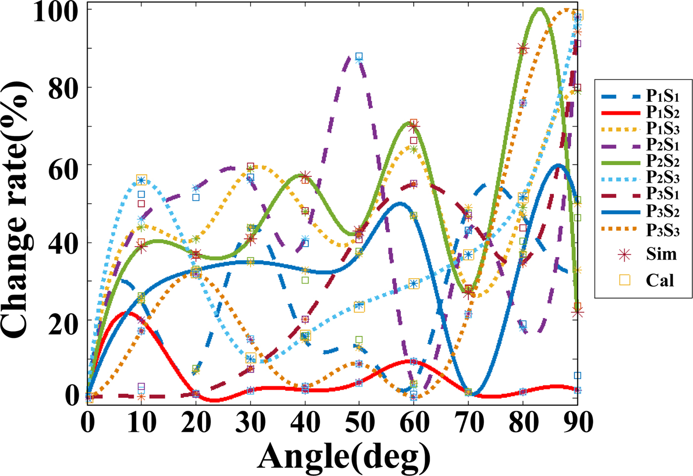
The curve of the comparison between the calculated and simulated mutual inductance change rate is shown in Fig. 6.
The change rate of different models versus angle misalignment.

As shown in Fig. 6, the calculation and simulation results are in good agreement. All of the change rate of model P1S2 is below 20%, so the P1S2 is chosen as the optimal design of the ball-shaped coil.
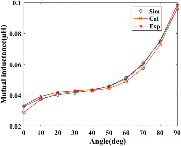
In order to reconfirm the correctness of the calculated and simulated results for mutual inductance with angular misalignment, the model P1S2 is chosen to measure its mutual inductance between primary and secondary coils at different angle misalignment. The results are compared with the calculated and simulated results in Fig. 7.
Comparison among the simulated, calculated, and measured mutual inductance with angular misalignment.

In Fig. 7, the “⋆” represents the measured mutual inductance, the “⋄” means the simulated mutual inductance, and the “○” represents the calculated mutual inductance. As shown in Fig. 5, the simulated and calculated results are closed to the measured mutual inductance. It demonstrates that the mutual inductance calculation model based on filament method is accurate and feasible.
D) Analysis of the magnetic field simulation for the proposed model
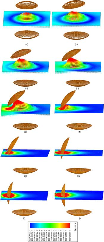
By using an electromagnetic simulator (Maxwell 3D), the magnetic field intensities and flux lines at different angle misalignment of the model P1S2 are shown in Figs 8(a)–8(j). The type of simulation is set as magnetic statistic. A net current of 1 A is excited on each wire. Both primary coil and secondary coil have fifteen turns with 0.316 mm wire diameter. The chosen magnetic plane is across the center of the both transmitting and receiving ball.
The magnetic intensities and flux lines of the model P1S2 at different angle misalignment: (a) 0°; (b) 10°; (c) 20°; (d) 30°; (e) 40°; (f) 50°; (g) 60°; (h) 70°; (i) 80°; (j) 90°.

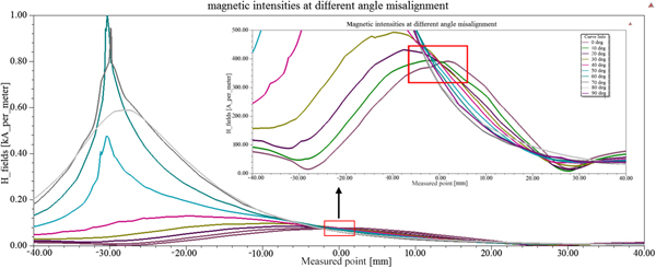
Figure 9 shows a comparison of the magnetic intensity H for the optimized model P1S2 with angular misalignment (0–90°) along the y axis, from the point (0,−40,0) to (0,40,0). The distance labeled 40 mm is the location of the transmitting and receiving ball center (0,0,0). The magnetic intensities of different angle misalignment in the red frame mean the magnetic intensities around the ball center. As shown in Fig. 8, the magnetic intensities have little difference around the ball center and the disturbance on the WPT system will be decreased with the proposed winding design.
Comparison of the magnetic intensities of the model P1S2 at different angle misalignment.

III. IMPLEMENTATION OF CIRCUIT FOR THE PROPOSED SYSTEM
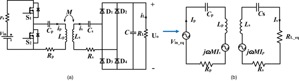
Figure 10(a) shows the overall topology of WPT system. The proposed system is for low power application, therefore, the half-bridge inverter is chosen as the inverter model because of its simplicity. The load of a WPT system is battery or charging circuit with battery generally. So, on considering the resistor is the most representative load, it is used in the hardware prototype for simplicity. Figure 9(b) is the equivalent topology of the overall WPT system, from which the relationship among the output power, resonant frequency, and load can be derived.
Topology of the circuit for the WPT system: (a) overall system topology and (b) equivalent topology of the overall system.

Equations (21) and (22) can be obtained by analyzing the equivalent topology in Fig. 9(b) based on KCL and KVL:
 $$P_L = \dot{I}_s^2 R_L = \displaystyle{{{(\omega M)}^2V_{in\_eq}^2 R_{L\_eq}} \over {{[R_p(R_s + R_{L\_eq}) + {(\omega M)}^2]}^2}}$$
 $$\eta = \displaystyle{{P_L} \over {V_{in\_eq}I_p}} = \displaystyle{{{(\omega M)}^2R_{L\_eq}} \over {[R_p(R_s + R_{L\_eq}) + {(\omega M)}^2](R_s + R_{L\_eq})}}$$
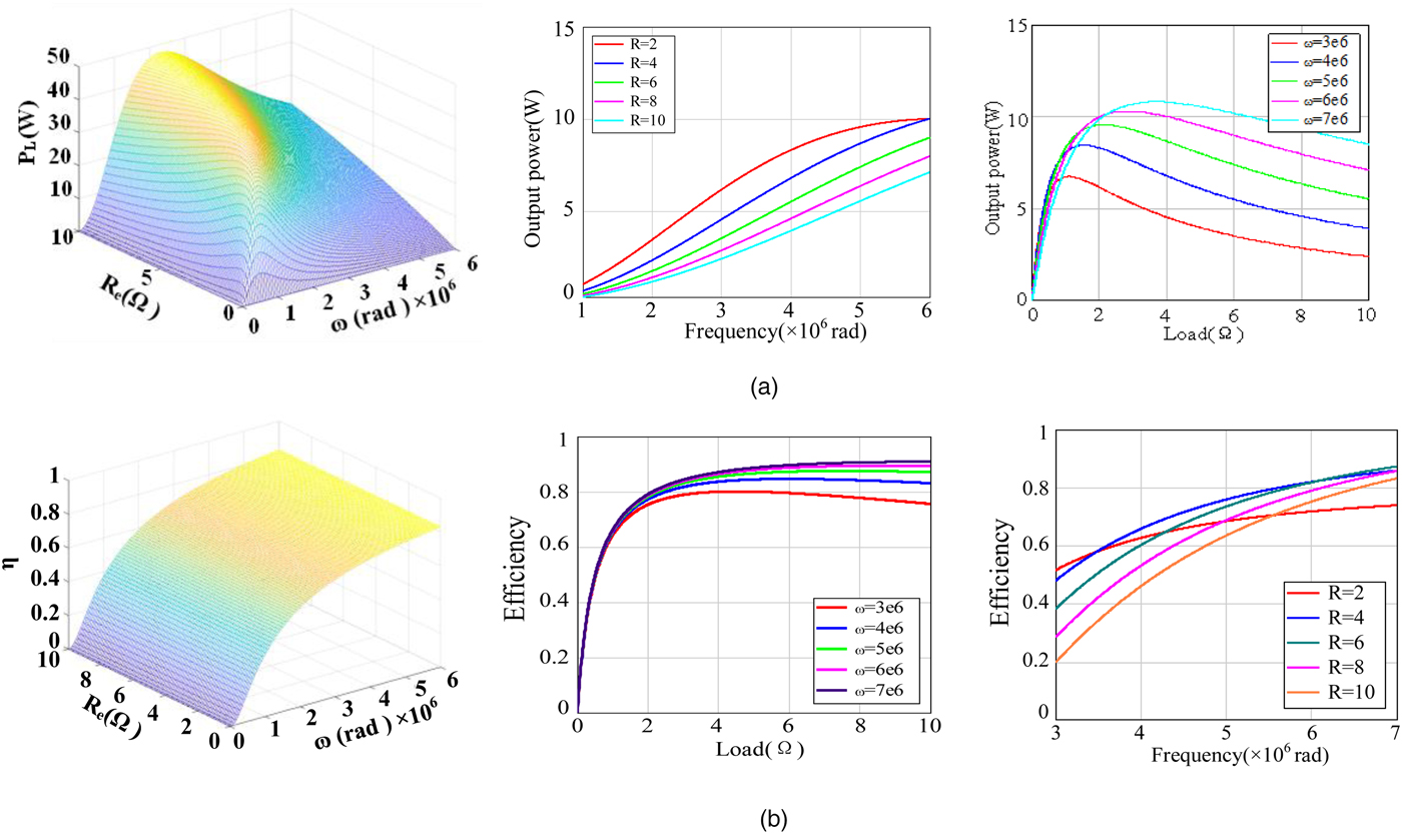
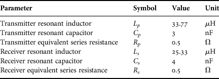
Based on equations (21) and (22), according to the system parameters shown in Table 4, the output power and efficiency of the system related to the working frequency and equivalent load is shown in Fig. 11.
The relationship among the several important quantities. (a) Output power versus resonant frequency and load. (b) Efficiency versus resonant frequency and load.

A set of parameters used for simulation.

The relationship among the output power, resonant frequency and the load is shown in Fig. 11(a), the system efficiency versus the resonant frequency and the load is shown in Fig. 11(b). As shown in Figs 11(a) and 11(b), there is a tradeoff between output power and efficiency. The output power increases and then decreases sharply as the resonant frequency goes up. However, the efficiency rises persistently and then levels off at a certain value as the resonant frequency increases. Therefore, it is necessary to choose an optimized resonant frequency and load value for the designed WPT system to obtain a proper output power and efficiency.
IV. EXPERIMENT
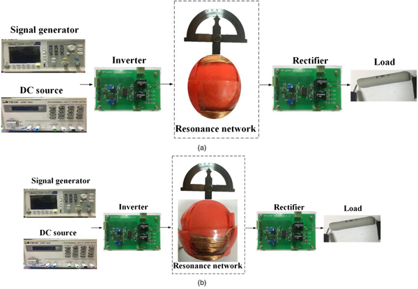
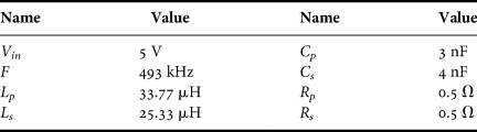
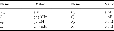
The experimental platform of the resonance network with model P1S2 and P1S1 is shown in Figs 12(a) and 12(b) respectively. It consists of a signal generator of supplying one electric signal with 500 kHz, a DC source for setting a 10 V voltage input, a inverter model for converting DC voltage to AC voltage, a resonance network with ball-shaped coil as primary and secondary resonance coil and an angle ruler to measure the angle misalignment between the primary and secondary coil, a rectifier model to converting AC voltage to DC voltage, and a load. The experimental parameters of the model P1S2 and P1S1 are shown in Tables 5 and 6 respectively.
Experiment platform: (a) resonance network with model P1S2 and (b) resonance network with model P1S1.

Experimental parameters of the model P1S2.

Experimental parameters of the model P1S1.

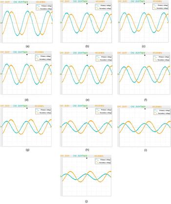
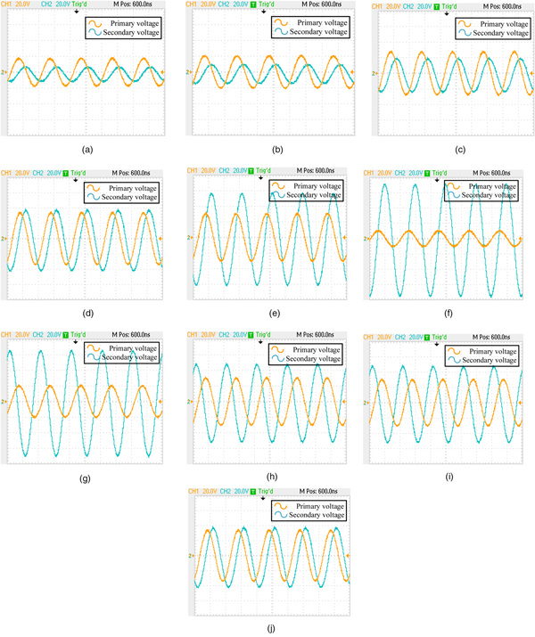
The primary and secondary voltages vary with angle misalignment of model P1S2 and P1S1 are shown in Figs 13 and 14 respectively. The specific value of the primary and secondary voltage of model P1S2 and P1S1 are shown in Tables 6 and 7 respectively. V p and V s are the voltage across the primary and secondary coil respectively. I p and I s are the current in the primary and secondary coil respectively.
The primary and secondary voltage versus angle misalignment of the model P1S2: (a) θ = 0°; (b) θ = 10°; (c) θ = 20°; (d) θ = 30°; (e) θ = 40°; (f) θ = 50°; (g) θ = 60°; (h) θ = 70°; (i) θ = 80°; (j) θ = 90°.

The primary and secondary voltage versus angle misalignment of the model P1S1: (a) θ = 0°; (b) θ = 10°; (c) θ = 20°; (d) θ = 30°; (e) θ = 40°; (f) θ = 50°; (g) θ = 60°; (h) θ = 70°; (i) θ = 80°; (j) θ = 90°.

The specific value of the primary and secondary voltages with different angular misalignment.

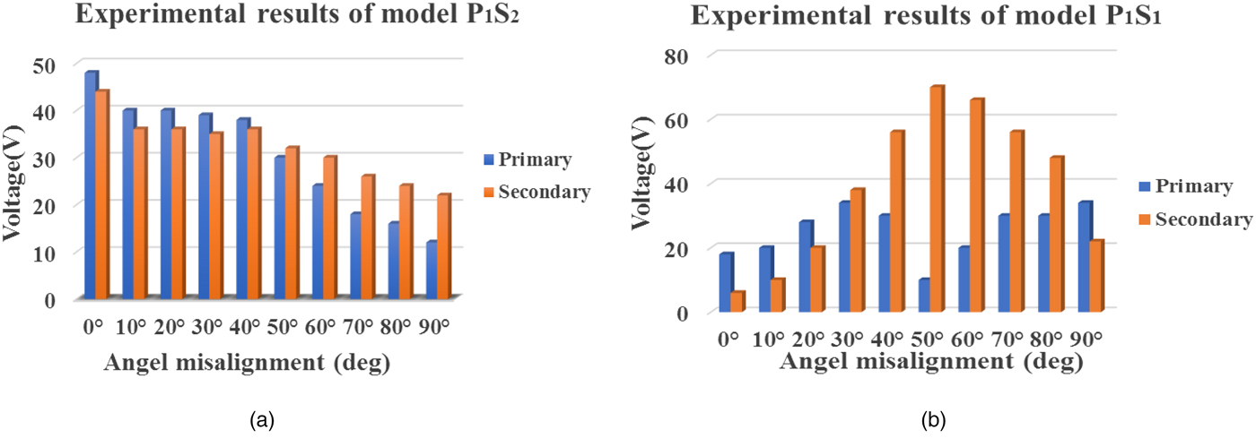
In order to show the change tend of the primary and secondary voltage for the model P1S2 and P1S1, according to the data from Figs 13 and 14, the rms values of the voltage have been expressed by the bar chart in Fig. 15.
Experimental voltage of the primary and secondary coils: (a) P1S2 and (b)P1S1.

As shown in Figs 15(a) and 15(b), the secondary voltage of the model P1S2 changes less than that of the model P1S1 and the secondary voltage of model P1S2 levels off between 0 and 60°. That means the mutual inductance of the model P1S2 change little with the angular misalignment, which coincide with the simulated results. The experiment results verify that the optimized model P1S2 proposed in this paper can really reduce the disturbance caused by the change of mutual inductance on the system.
The specific values of the primary and secondary voltages of model P1S2 and P1S1 are shown in Tables 7 and 8 respectively. V p and V s are the voltage across the primary and secondary coil respectively. I p and I s are the current in the primary and secondary coils respectively.
The specific value of the primary and secondary voltages with different angular misalignment for the model P1S1.

According to data in Tables 7 and 8, it demonstrates clearly that the secondary voltage of the optimized model P1S2 levels off between 0 and 60°, however, the secondary voltage of the model P1S1 increases sharply between 0 and 50°, and then drops dramatically from 60 to 90°. Therefore, the experimental results re-testify the correctness of the calculation results of the mutual inductance for the optimized model P1S2.
IV. CONCLUSION
Nowadays, more and more robots are used in both industry and human-related applications. With the development of WPT technique, in the near future, WPT systems with moveable coils will be widely applied in the robotic arms due to the benefit of highly flexibility, highly integration, and low cost. In order to make an optimized design and accurate calculation of the ball-shaped coil, a precise calculation model of the mutual inductance for free-rotating ball-shaped coils based on the filament method is proposed in this paper. The mutual inductance of several different kinds of winding structures is calculated. And simulation of the ball-shaped model has been conducted using Maxwell 3D, which has been compared with the calculated and measured results to verify the accuracy of the established calculation model. Based upon the comparison and analysis, an optimized winding structure with minimized mutual inductance changing rate is acquired. Then, the magnetic intensity of the proposed model is simulated. In addition, the relationship among output power, efficiency, resonant frequency, and load parameter for the ball-shaped coil WPT system are analysis in detail. Finally, an experimental platform including inverter module, rectifier module, resonant module with ball-shaped coils is built. The system efficiency is up to 80% between 0 and 60° angular misalignment. Therefore, the proposed model design P1S2 is fit for joint movement within 60°.
 Yang Yang received her B.S. degree in electrical engineering from Nanjing Agricultural University, Nanjing, Jiangsu, China, in 2017. She is currently pursuing her M.S. degree at Xi'an Jiaotong University, Xi'an, Shaanxi, China. Her current research interests include wireless power transfer and electromagnetic interference.
 Wenjie Chen received her B.S., M.S., and Ph.D. degrees in electrical engineering from Xi'an Jiaotong University, Xi'an, China, in 1996, 2002, and 2006, respectively. Since 2002, she has been a member of the faculty of the School of Electrical Engineering, Xi'an Jiaotong University, where she is currently a Professor. From January 2012 to January 2013, she was with the Department of Electrical Engineering and Computer Science, University of Tennessee, Knoxville, TN, USA, as a Visiting Scholar. She then came back to Xi'an Jiaotong University, and involved in teaching and research wok in power electronics. Her main research interests include electromagnetic interference, active filters, and power electronic integration.
 Liyu Dai received his B.S. degree in electrical engineering from Fuzhou University, Fuzhou, China, in 2017. He is currently working toward his M.S. degree in power electronics in the School of Electrical Engineering, Xi'an Jiaotong University. His research interests include electromagnetic interference and active filters.
 Rui Wang received his B.S. degree in electrical engineering from Xi'an Jiaotong University, Xi'an, China, in 2017, where he is currently working toward his M.S. degree in power electronics in the School of Electrical Engineering. His research interests include sound field optimization and active noise reduction technology for the filtering field of converter station.