I. INTRODUCTION
Spherical indentation has often been used for the determination of materials characteristics such as elastic modulus, hardness, and elastic–plastic properties.Reference Field and Swain1–Reference Bell, Bendelli, Field, Swain and Thwaite3 One of the main reasons for the popularity of these measurements was that with a spherical indenter and sufficiently low loads essentially reversible deformations could be obtained. The contact problem can be solved relatively simply by Hertz equations, and the elastic constants of the material are easily calculated. Such an idea was very advantageous also for the determination of viscoelastic properties of polymers, where low deformations would lead to suppression of irreversible flow of the material and the viscoelastic properties of the polymer could be determined.Reference Oyen4–Reference Menčík, He and Němeček8 Further, the stresses in many applications susceptible to creep are usually low and the viscoelastic deformations are reversible and disappear some time after unloading. Therefore, the stresses in the indentation tests for the determination of the viscoelastic model parameters should also be low. This cannot be achieved by a pointed indenter, but by a spherical one. However, a proper measurement of the indentation response at low loads was rather complicated for several reasons: first, instruments capable of applying such low loads were not available until recently. Only the new generations of indentation systems can apply sufficiently low loads and measure corresponding depths. Second, the thermal driftReference Menčík, He and Němeček8–Reference Nohava, Randall and Conté14 has become a growing concern for long-term measurements required for the determination of the creep characteristics of polymers. Thus, the problem of thermal drift had to be analyzed and included into the analysis of the data. Third, with the use of extremely low loads and depths, the question about the sphericity of the indenter became an important issue, and the effective radius of the indenter must be determined in the range of a few tens of nanometers or less.
The first part of this article deals with the phenomenon of thermal drift and sphericity of the indenter. So far, the effect of thermal drift has limited the duration of creep measurements to only several minutes. However, in many applications the creep times are much longer: an indentation system that has a negligible thermal drift therefore has to be used for creep tests in duration close to that of real applications (tens of minutes or even longer). The thermal drift can be calculated as the change in the displacement signal during indentation under constant load on a sample not exhibiting time-dependent properties (e.g., fused silica).Reference Nohava, Randall and Conté14
Although most spherical indenters are provided with a constant radius, this value is nominal and there have been doubts about its validity in small ranges.Reference VanLandingham15 It was therefore decided to verify the sphericity of the indenter experimentally. The effective radius of a spherical indenter can be calculated using the modified Hertz formula, supposing that the contact deformations are only elastic:
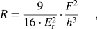
where R is the radius of the indenter, E r is reduced modulus, F is the indentation force, and h is the indentation depth.
The primary goal of the second part of this article was to determine the viscoelastic properties of the polymethylmethacrylate (PMMA) at low loads where the creep could cease after a long hold period. The indentation loads were deliberately set very low to remain in the elastic regime where the deformation of the PMMA would be reversible. The model proposed by Mencik et al.Reference Mencik, He and Swain7, Reference Menčík, He and Němeček8 was applied to the results obtained by spherical indentation so that the viscoelastic properties of the polymer could be determined. This model is based on low deformations and using a spherical indenter with a constant radius. However, as the radius of the indenter can vary at low depths, one should consider using a function R = R(h) when fitting the h(t) data, instead of R = const. Therefore, the indenter radius in respect to the indentation depth has to be known.
II. EXPERIMENTAL DETAILS
A. Materials and instruments
The experiments were performed on a specimen cut off from a commercial sheet PMMA (dimensions 10 × 10 × 5 mm3) glued on a steel block. This block was held in a vice to eliminate the problem of eventual creep of the PMMA if it would be directly held in the vice. A fused silica (FS) cylinder with 5-mm thickness and 25-mm diameter was used for thermal drift and indenter radius determination. The Young’s modulus of the FS was 73.2 ± 2.1 GPa and Poisson’s ratio 0.16. The indenter used in all experiments was a spherical indenter with nominal radius of 100 μm made of ruby. The mechanical properties of ruby are close to those of sapphire, and in our calculations we assumed Young’s modulus of 400 GPa and Poisson’s ratio of 0.3. Indentation system used in all measurements was the Ultra Nanoindentation Tester (UNHT) manufactured by CSM Instruments (Peseux, Switzerland). This instrument, described in more detail elsewhere,Reference Nohava, Randall and Conté14 features extremely low thermal drift, which is corrected neither by hardware nor software procedures. This is very important since no assumptions on the thermal drift were necessary (as if thermal drift corrections were used). The thermal drift of the instrument was nevertheless measured during a hold period on FS.
B. Calibration of the indenter radius
The effective indenter radius was determined using indentation on FS. Two loading modes were used: single-load indentation and Continuous Multi-Cycle (CMC) indentation. Both methods allow the determination of the radius of the indenter using Eq. (1) provided that the indentation is done in elastic regime. When elastic–plastic deformation is reached, the Oliver and PharrReference Oliver and Pharr16 or Field and SwainReference Field and Swain1 approach shall be used.
In the single-load indentation, the radius R was calculated for each data point during the loading phase. The indentation parameters were maximum load 50 mN, loading and unloading times 30 s, and 5 s hold at the maximum load. Approximately 500 data points were acquired during the loading.
The CMC procedure consisted of 20 repeated loading–partial unloading cycles. The maximum load in each subsequent cycle was increased from the initial value of 0.5 mN up to the final value of 50 mN. The unloading was set to 20% of the maximum force in each cycle. For each cycle of the CMC procedure, the maximum load and depth were measured and then used for the calculation of the radius of the indenter according to Eq. (1).
C. Verification of thermal drift
Thermal drift verification was performed by indentation on the same FS at loads of 1, 5, 10, and 50 mN. The loading and unloading times were set to 5 s (15 s for the 50-mN load), and the pause at the maximum load was set to 1800 s (30 min). The variation of the displacement signal was measured during this period.
D. PMMA creep experiments
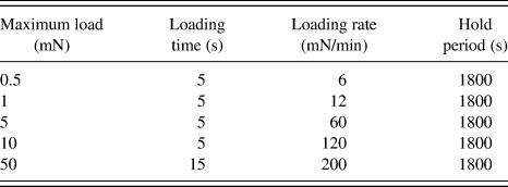
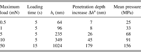
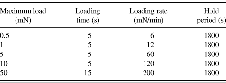
Measurement of viscoelastic properties was realized on PMMA with indentation parameters given in Table I. The experiments were done with a fast increase of the load followed by an 1800-s lasting hold.
Parameters of indentation creep measurements on polymethylmethacrylate (PMMA).
The creep of the PMMA (i.e., increase of the indentation depth while the force was kept constant) was monitored. The growth of indenter depth in time during the hold at the maximum load, h(t), was approximated by a model consisting of a spring (C 0) in series with two Kelvin–Voigt bodiesReference Mencik, He and Swain7, Reference Menčík, He and Němeček8:

where m = 3/2, K = 3/(4√R), and constants C 1, C 2, …Cn are compliances pertaining to the relaxation times τj; n = 2. The constants ρj defined by
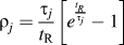
correct the fact of that the load grows to the nominal value during some time t R; see Ref. Reference Oyen17. The instantaneous compliance C 0 is related to the reduced instantaneous modulus as

and E r is related to the specimen modulus E and indenter modulus E i as
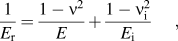
where ν and ν i are the Poisson ratio of the sample and the indenter, respectively. The constants were calculated using a least-square fitting procedure of the displacement–time data obtained during the hold period.
III. RESULTS
A. Verification of thermal drift
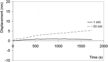
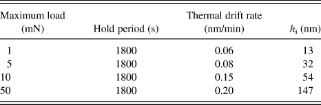
The values of thermal drift of the UNHT system measured on FS are given in Table II. Although the thermal drift varied with the force applied, it remained nevertheless very small: generally below 0.1 nm/min for lower loads but not more than 0.2 nm/min for high loads (see Fig. 1). Although one could consider such values of thermal drift relatively high, it has to be considered that they represent a real signal of the whole measuring chain including the electronics and environment, which was by no means corrected. Even in the worst case (0.2 nm/min for the 50-mN indentation), the thermal drift would result in an error of 0.2 nm for a 1-min lasting indentation or 6 nm in a 30-min lasting indentation. These values are in almost all cases negligible in respect to the measured signals and often lay well below the scatter of experimental results. Long-term and creep measurements can therefore be performed by the UNHT without any thermal drift correction and its supposed (most often) linear approximation.
Comparison of thermal drift measured during 30-min hold at 1 and 50 mN.

Thermal drift measured on fused silica.
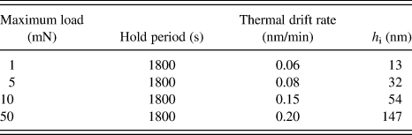
hi is the depth at the beginning of the hold period.
B. Indenter radius
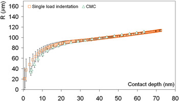
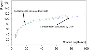
The calculation of the indenter radius showed that the spherical indenter with nominal radius of 100 μm has actually a smaller radius at lower depths (see Fig. 2). The nominal value of 100 μm was reached above ∼25-nm depth. The results obtained from single-load indentation and cyclic indentation agreed very well although some discrepancy was found at the lowest depths. This is very likely because of the fact that below 10-nm depth many other factors are playing important role in the measurement (surface contamination, roughness, real point of contact on the indenter, etc.).
Evolution of indenter radius with the distance (contact depth) from the tip.

C. Viscoelastic properties of the PMMA
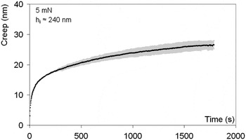
The measurements of the viscoelastic properties of the PMMA were performed at several loads with 1800-s long hold period at the maximum load. The loading rates varied between 6 and 200 mN/min (see Table III). The viscous properties of the PMMA could therefore be determined using a large range of loading profiles and consequently with high reliability. A typical example of indenter depth evolution is shown in Fig. 3 (5-mN load, 1800-s hold period). As noted above, no correction to the displacement signal was done in all creep experiments.
Creep of polymethylmethacrylate (PMMA) during a hold period of 1800 s at 5-mN load. h i is the depth at the beginning of the hold period. The grey area shows the scatter of experimental results.

Increase of penetration depth in PMMA during a hold period of 1800 s.
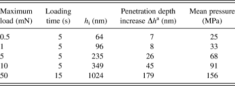
a h i is the penetration depth at the beginning and h f the penetration depth at the end of the hold period. The penetration depth increase was calculated as Δh = h f – h i.
Although the creep deformation was relatively large (∼180 nm) at higher loads (50 mN), the creep was quite small (∼7 nm) at the lowest load (0.5 mN). The experiments at low loads were performed to reach a steady state where the flowing of the PMMA will cease. This was possible only for small loads and in elastic regime, while at higher loads the irreversible deformations were induced in the material and the flow would cease after a very long hold period (∼several hours). The creep data (growth of depth during hold period) was fitted using Eq. (2) with spring and two Kelvin–Voigt bodies. For the 5-mN load, the parameters of the fit were C 0 = 2.45 × 10⁻¹⁰, C 1 = 7.40 × 10⁻¹¹, C 2 = 1.40 × 10⁻¹⁰ (all m2/N), τ 1 = 19 s, τ 2 = 187 s. The reduced instantaneous elastic modulus E r, calculated via Eq. (4) as 1/C 0, was 4.09 GPa.
IV. DISCUSSION
A. Creep experiments and thermal drift
The creep tests on PMMA and FS showed that if low pressure is to be maintained to avoid irreversible changes to the material, low thermal drift is indispensable. At low loads however, the changes in penetration depth are relatively small and only a few times larger than the thermal drift. Even for an instrument showing extremely low thermal drift, such experiments will be subject to relatively high scatter of data. For an indenter with given radius, it is therefore necessary to increase the loads so that the thermal drift can be considered as negligible. In the case of a spherical indenter with 100 μm radius and the UNHT system, the lower limit for reasonable creep measurements on PMMA is ∼5 mN. At such loads, the mean pressure is still relatively low (∼68 MPa) while the change in penetration depth during the hold period is 26 nm. With a thermal drift of 0.08 nm/min the error in displacement signal over 30 min is 2.4 nm, i.e., less than 10% of the depth increase. At the same time, the pressure is low enough to ensure that irreversible changes in the PMMA will not occur. The creep experiments therefore have to be properly designed to remain in the elastic region but to show growth in depth sufficiently high so that the thermal drift can be neglected.
Another important factor is the duration of the creep experiment: in many engineering applications, the creep times are relatively long, from several tens of minutes up to several hours. Similar hold period must therefore be included in the creep experiments to obtain relevant data for modeling of viscoelastic properties. Low thermal drift must be ensured during such measurements since it is very difficult to predict the evolution of thermal drift for depth corrections in case of such long experiments.
An important issue in mechanical testing of polymers is their sensitivity of yield strength to pressure.Reference Eswar Prasad, Keryvin and Ramamurty18 In certain cases – mainly at higher loads – the yield strength can depend on the pressure under the indenter. However, the contact pressure and indentation strain in most of our indentation experiments were relatively small, and the effect of pressure sensitivity could therefore be neglected.
B. Indenter radius
The eventual imperfections in the indenter geometry (the effective radius being different from that of the nominal one) were thought to influence the creep behavior. If the indenter radius R would change with the indentation depth, the parameter K in Eq. (2) defined as K = 3/(4√R) cannot be considered as a constant, but should be fitted as well. In such a way the effective radius could also be determined by a measurement on PMMA. Simpler, however, would be to use the calibration of the spherical indenter on FS as described previously [Fig. 2 and Eq. (1)]. This calibration yields a relation between the contact depth and the effective radius of the indenter and can therefore be used in the calculation of K for a given depth. Fortunately enough, using a relation R = R(h) was not necessary in our experiments as the radius of the indenter was shown to reach its nominal value at depths of approximately 25 nm and more. The minimum depths in the creep experiments on PMMA were ∼64 nm where the indenter already could be considered as a sphere with a constant radius.
The results in Fig. 2 show that the radius of the indenter varies strongly between 0- and 25-nm depth, while above 25 nm it becomes nearly constant. The slight increase of the indenter radius as calculated from both single-load and CMC measurements can be attributed to the fact that the calculations were based on purely elastic deformations using the Hertz formulae for spherical contact. However, at contact depths above ∼50 nm the maximum pressure under the indenter reached 1200 MPa, which is above the yield strength of FS (1100 MPa).Reference Proctor, Whitney and Johnson19 The Hertz formulae for contact depth (hc = h/2) are then inappropriate and the Oliver–Pharr approachReference Oliver and Pharr16 shall be used. This was possible only for the CMC indentations, as in each cycle also the contact stiffness was calculated. In single-load indentations, contact stiffness was calculated only once during the unloading phase. Figure 4 shows a comparison of the effective radius plotted against contact depth calculated by Oliver–Pharr approach (round symbols) above contact depth of 50 nm. The radius of the indenter is more stable and closer to the nominal value of 100 μm.
Radius of the indenter as a function contact depth calculated by Hertz (triangular symbols) and Oliver and Pharr approach (round symbols).

However, the fact that due to the geometrical imperfections the indenter radius cannot be considered as constant, complicates to some degree other methods derived from nanoindentation, namely that of stress–strain curve determination.Reference Tabor20–Reference Bell, Field, Swain, Nix, Bravman, Arzt and Freund23 In such measurements the indentation depths and loads are kept very low to remain in the elastic regime. At such depths the precision in determining the effective radius of the indenter is a crucial factor for proper calculation of the stress–strain characteristics of the material. This is very limiting especially in the case of thin films where the maximum depths are limited by the influence of the substrate, which should remain negligible.Reference Schwarzer, Chudoba and Richter9, Reference Chudoba and Richter10 It is therefore recommended to perform a thorough calibration of the indenter radius before such measurements are to be realized.
V. CONCLUSIONS
The phenomena of thermal drift, sphericity of ball indenters, and viscoelastic properties of PMMA were investigated in this article. It was shown that the radius of a ball indenter varies at low penetration depths, while it can be considered as constant for larger depths. Indentation under constant load on FS showed that the UNHT has a very low thermal drift (below 0.2 nm/min) and in most cases correction of thermal drift is not necessary. The measurements of thermal drift were closely related to the determination of viscoelastic properties of PMMA as the thermal drift adds to the depth growth, especially during long-term measurements. The determination of the viscoelastic properties of PMMA showed that if the experiment is designed properly, both thermal drift and imperfections in the ball indenter geometry can be neglected. It was shown that the model proposed by Mencik et al.Reference Mencik, He and Swain7, Reference Menčík, He and Němeček8 can successfully be used for the determination of viscoelastic properties of polymers, especially at low loads and long hold times.