


Discovery and Scientific Importance of Vostok Subglacial Lake
On 5 February 2012, deep drilling of the inland ice sheet at the Russian Antarctic Vostok station, a multi-year project, was completed. This event was accompanied by unsealing of the water body of Vostok Subglacial Lake, discovered by an international team of scientists in 1994. The subglacial lake is located directly beneath Vostok station (Reference LukinLukin, 2012). The success of the Russian drillers who conducted these complex technological operations has attracted the interest of both the international Antarctic community and the media in many countries. Future studies of the water body and bottom sediments of the largest subglacial water reservoir on Earth are fundamental for understanding biodiversity and the evolutionary processes of living organisms under unknown habitat conditions. Also, the study of the geological structure of the Antarctic continent during the period before its glaciation, and the preparation of technologies and equipment to search for living organisms on the other planets of the solar system, will be useful outcomes of future research.
Ice-Sheet Drilling Methods, Technology for Penetrating Vostok Subglacial Lake and Environmental Impact Assessment
Implementation of the project was accompanied by multi-year discussion of the ecological cleanliness of the Russian technology for water sampling from the lake surface layer. The problem was that ‘dry’ drilling of glaciers is possible only to 500 m depth. Below this level, the ‘overburden pressure’ effect narrows the borehole diameter. This process develops more intensively with increasing borehole depth. To compensate for the overburden pressure effect, different borehole fluids are applied in the practice of drilling. Most widespread in deep ice drilling are a mixture of kerosene and Freon®, butyl acetate (Reference Talalay and GundestrupTalalay and Gundestrup, 2002) and hot water (the first type of borehole fluid is used in ice drilling by specialists in Russia and the European Union, the second in Japan and the third in the USA). These fluids should have two main characteristics: be non-freezable and be close to the ice density, 0.91 gcm–3. Fluids based on kerosene or diesel fuel have been actively applied in ice-core drilling of most deep boreholes. Butyl acetate is much less widely used due to its toxicity to humans, and hot water is used for non-core borehole drilling. A source of major concern to some parts of the Antarctic community was an assessment of possible contamination of relict waters of Vostok Subglacial Lake by borehole fluids consisting of hydrocarbon ingredients. Accordingly, the Scientific Committee for Antarctic Research (SCAR) in 1998 recommended that Russia halt drilling operations in deep borehole 5G at Vostok station at a minimum safe depth until an environmentally clean technology for penetrating to the sub-glacial lake was developed. At the end of January 1998, the depth of this borehole was 3623 m, and based on independent estimates of the ice-sheet thickness by means of seismic logging in the deep borehole and radio-echo sounding (RES), it was 3750±20 m (Reference Masolov, Popov, Lukin, Sheremet’yev, Popkov, Fütterer, Damaske, Kleinschmidt, Miller and TessensohnMasolov and others, 2006).
At the end of 1998 the Ministry for Education, Science and Technology of the Russian Federation declared an open competition for developing a technology for ecologically clean water sampling of the surface layer of Vostok Subglacial Lake through deep ice borehole 5G. The competition was won by a joint team of the St Petersburg Mining Institute (now the Mining University) and the Arctic and Antarctic Research Institute, St Petersburg, headed by Boris Kudryashov. The work was completed at the end of 2000, and in March 2001 the design was approved by the State Ecological Expert Examination Commission of the Russian Federation.
The technology was as follows. The ice-sheet stratum above the lake water is floating on the water below, and the pressure at the ice/water interface corresponds to the weight of the ice column (overburden pressure). The overburden pressure at the point of ice drilling is compensated by the hydrostatic pressure of the drilling fluid in the borehole. Reducing the amount of drilling fluid, one can provide under-compensation of the overburden pressure, creating lake water pressure at the ice/water interface greater than that of the drilling fluid column.
Under such conditions at the moment of contact between the borehole bottom and the lake surface, the drilling fluid, being lighter than water with density equal to 1.00 gcm– 3, should be expelled by lake water up the borehole to a height corresponding to the under-compensated overburden pressure. Penetration of the drilling fluid to the lake is excluded as it is hydrophobic. Surface lake water rising up the borehole will freeze after some time as it encounters freezing conditions at the ice borehole sides. The next season, this ‘fresh frozen’ ice core will be drilled and recovered to the surface for further geochemical, glaciological and microbiological studies.
In July 2001, this project was presented as a working paper at the 24th Antarctic Treaty Consultative Meeting (ATCM XXIV) in St Petersburg (ATCM, 2001). The next year, at ATCM XXV in Warsaw, Poland, the Russian Federation delegation presented a Draft Comprehensive Environmental Evaluation (CEE) for the developed water-sampling technology. After wide discussion of this project, an Intersession Contact Group of experts (ICG) was set up, representing different parties to the Antarctic Treaty, which was acquainted in detail with the proposals of the Russian side and prepared questions and comments on the project (Russian Federation, 2002). At ATCM XXVI in Madrid, Spain, the Russian Federation presented the Revised CEE for the project with answers to the questions and comments of the ICG. In accordance with the methodological instructions of the Committee of Environmental Protection (CEP), this CEE included the following sections:
Introduction
Description of proposed activity
Characteristics of subglacial Lake Vostok
History of ice-sheet drilling at Vostok station. Background information
Technology of water sampling of Lake Vostok
Parting drilling fluid
Stages and planning of proposed activity
Monitoring program. Collection of additional necessary information to initiate the proposed activity: Continuation of drilling additional 50 m (from 3623 m to a depth of 3673 m) (seasons 2004–10)
First stage. Borehole drilling by the electrical-mechanical drill from 3673 m to a depth of 3725 m (2010/11)
Second stage. Borehole drilling until the contact with the lake surface (2010/11 or 2011/12)
Justification of the need and advisability of proposed activity
Alternative types of activity
Response actions in emergency
Major expected results
Area of proposed activity
Types of expected production and domestic waste and methods of their utilization and removal
Oil and oil-containing mixtures
Sewage waters
Garbage (including solid kitchen waste)
Description of the environment in the operation area
Glacial cover in the borehole area
Characteristics of the current state of borehole 5G-2
Crystallographic and structural properties of lake ice with respect to its permeability for the drilling fluid
Probability of changes in physical and structural properties of lake ice (towards its permeability increase) within a depth range from 3650 m (current borehole bottom) to 3750 m (estimated depth of the ice/water interface)
Climate of the area
Geophysical data on the area of Lake Vostok
Peculiarities of the gas regime of Lake Vostok in the context of penetration to the lake with the purpose of water sampling
Water salinity of Lake Vostok
Microbiological studies of deep horizons of the ice sheet
Viability of bacterial cells
Molecular-biological studies of microbial diversity in deep horizons of Lake Vostok accretion ice
Biota in the activity area
Microbial diversity in the drilling fluid of the borehole
Anthropogenic load on the environment of the area
Analysis of the environmental impact
Identification of impact sources
Impact agents
Types of activity
Areas of activity (impact)
Analysis of significance of the anticipated environmental impact
Anticipated impact on environmental compartments
Direct impact and contamination risks
Possible indirect or secondary impact
Total (cumulative) impact
Anticipated impact on the aesthetic and wilderness values of the environment
Anticipated impact on the areas of scientific, historic and cultural significance
Unavoidable environmental impact at continuation of drilling the borehole 5G-2 and penetration to Lake Vostok
Risk of the impact of lake microorganisms on the human health and the environment
Proposals for mitigating the environmental impact
Gaps in knowledge
Conclusions
As a result of the new discussion, the CEP members, who consider these issues within the ATCM structure, prepared new questions and comments, which were accepted by the ATCM and included in the Final Report (Russian Federation, 2003). In compliance with the procedure set forth in Annex V of the Protocol on Environmental Protection to the Antarctic Treaty in 1991, the implementation of which is provided by the CEP, the available answers to such questions make it possible for the Treaty Party, which prepared the Draft CEE, to develop the Final CEE and decide at national level about the practical realization of the project. However, some of the questions could be answered only after continuation of ice drilling in borehole 5G at Vostok station.
One of the most complicated problems was the need to test the ecological purity of the Russian technology under field conditions. In practice, this meant a search for another subglacial water body in Antarctica, investigation of its characteristics by RES methods and new drilling of the glacier. The authors of this proposal believed that such an approach was impossible for any Antarctic Program to fulfil, but a way out of this most difficult situation was discovered unexpectedly. In 2003, specialists from Denmark carried out ice drilling in northern Greenland (North Greenland Ice Core Project (NGRIP) borehole). The ice drill unexpectedly encountered a water lens, which had not been detected during the preliminary RES of the glacial strata using geophysical methods to choose the drilling site. The European specialists in ice-sheet drilling use a borehole fluid consisting of a kerosene–Freon® mixture, similar to the Russian technology. The level of borehole fluid at the moment of penetration to the water lens was decreased. As a result, after the drill–water contact, water rose in the borehole to a mark corresponding to the pressure deficit between borehole fluid pressure and water pressure. The drill was extracted to the surface and in a year the ‘fresh frozen water’ that had risen up the borehole was drilled out. Further analysis of this ice core showed that only its upper 10cm was contaminated with the kerosene–Freon® mixture. Beneath this segment the ice was absolutely clean (Reference TalalayTalalay, 2005). The Danish specialists carried out an independent field expert examination of the Russian technology for penetration to Vostok Subglacial Lake. Its results confirmed in practice the validity of the theoretical notions of the Russian specialists.
Continuation of Ice-Sheet Drilling at Vostok Station
The results of drilling operations in Greenland allowed the Russian Antarctic Expedition (RAE) to continue drilling in borehole 5G at Vostok station in the 2006/07 austral summer. After an 8 year hiatus, the borehole was reactivated, a unique case in the history of glacier deep drilling. Because seasonal operations are limited to just 2 months (December–January) due to climatic conditions at Vostok station, it was possible to drill only 27 m of new ice core in the 2006/07 season, when the borehole reached a depth of 3650 m. Starting in December 2007, it was planned to perform continuous drilling year-round. However, two serious accidents at depths of 3658.26m (on 13 January 2008) and 3668 m (on 28 October 2008) resulted in breakdown and subsequent loss of the drill at these depths. In the first case it was possible to recover the damaged drill to the surface, while in the second case all attempts failed. In January 2009, it was decided to bypass the accident area, using borehole deflection from the vertical, a method developed at the St Petersburg Mining Institute and already successfully used in Antarctica. The borehole deflection was started from 3590 m depth, making it possible to move from the faulty drill horizontally over a distance of 1.5 m. This procedure also allowed us to obtain other ice-core samples with mineral inclusions, which had earlier been found in the 3607–3611m layer and were of greater interest for further scientific studies. At the end of January 2010, the depth of the new borehole 5G2 was 3650 m. Drilling continued in the 2010/11 season, in spite of serious technical problems arising with the drilling of ‘warm’ ice. In January 2011, 70.5 m of new ice core were obtained. On 5 February 2011 (end of seasonal operations at Vostok station in 2010/11), the borehole depth was 3720.47 m.
Penetration to Vostok Subglacial Lake
Before the beginning of the 2011/12 season, 3 0 ± 2 0m of ice remained between the bottom of the borehole and the ‘ice/water’ boundary. Taking into account that the ice drilling rate in the last week of the 2010/11 season was 1.8 m d–1, it was assumed that the remaining 10-50 m of ice could be drilled during January 2012. Ice drilling in the borehole began on 2 January 2012.
On 13 January the borehole depth reached 3738.5 m. At this point, technical problems affected the load-carrying cable, forcing drilling to stop. During this period, new geophysical observations of temperature and pressure at the borehole bottom were made and a borehole segment was drilled to 136 µm diameter in the 3720-3738.5 m layer. Drilling operations proper were resumed on 20 January. Until 31 January the average daily drilling rate was 1.5-2 m d–1, and on the last day of January the borehole depth reached 3760 m. The maximum depth of the ‘ice/water’ boundary according to seismic and radar data was not more than 10 m from the aforementioned depth. New data on ice temperature at the borehole bottom showed that the calculated melting point at this pressure should occur at 3766±16m. The drilling season had to end not later than 6 February 2012, when project participants were to leave the station on the last aircraft of the season.
To penetrate the ice/water boundary we planned to switch to a thermal drill and add special organic silicon fluid to the lower part of the borehole. The switch to a thermal drill was envisaged as a continuous cycle with a complete absence of the descent-ascent of the drill. The switch to a new type of drilling and introduction of a new component of the drilling fluid on the basis of silicon compounds would require interruption of the drilling process for a minimum of 2-3 days. This meant that, in practice, drilling by the thermal method in summer 2011/12 was impossible in principle due to the strict time limit. The drill recovery to the surface after adding the separation organic silicon fluid to the borehole bottom would have upset the entire penetration technology, as during the recovery this fluid would have been mixed with the main borehole fluid based on kerosene and Freon®. Therefore the project participants decided to continue drilling with the electromechanical drill up to the last available moment, i.e. until notified of the departure of the aircraft for Vostok station from Progress station.
On 4 February, when the borehole bottom reached 3766 m depth, there was an ice core on the bottom ~1.5m long, which had not been broken free in the previous run. After the end of the new run, breaking of the ice core separated a piece of ice ~0.75 m long. The force of breaking free the ice core and hence extension of the carrying cable were much greater than expected. The drill was then lowered to the bottom again and the remaining piece of ice core was broken free. During ice-core separation the driving motor is switched off, the core barrel does not rotate and the pump does not work, so there is no fluid circulation. While the upper section of this last ice core did not appear to differ from the specimens located above it, the sides of the lower section were ‘glazed’, as if the ice core were in contact with warmer water. After the next launch of the drill, no further ice drilling was able to take place. As soon as the drill touched the bottom, the drilling fluid circulation stopped. The drill filter contained frozen water instead of mud, which enveloped the entire internal surface of the filter net. Water freezing occurred in the upper borehole horizons, where the temperature of the borehole sides is about -558C. Breaking off the first ice-core section caused lake water to flow into the borehole along the hydraulic fracture formed due to the pressure difference between lake and borehole. Water from the subglacial lake, under ~377 at (~38 x 106Pa) pressure, several atmospheres greater than the pressure in the borehole fluid, which was reduced further by the attempts to break off the last ice core, rushed to the lower part of the borehole and as a result was extracted to the surface. We thus obtained the first samples of lake water, which were collected in special sterilized glassware.
On 5 February at 20:25 Moscow time, at a depth of 3769.3 m (by the ice-core length), contact between the drill boring bit and the lake water body was registered by the load sensor on the bottom and the momentum sensor on the boring bit in the process of ice cutting. The main objective of the drill operators was immediate recovery of the drill to the surface. The boring bit diameter is 135 mm, while the diameter of the ice borehole is slightly larger. However, there is a small clearance between the coring tube surface of the drill and the sides of the borehole, which will immediately be filled with water under pressure. The ice borehole sides are below freezing temperature everywhere above the ice/water interface, so the seeped super-thin water layer would freeze almost immediately and then it would be impossible to recover the drill to the surface. The operation regime of the drill winch was changed from ‘descent’ to ‘ascent’ within 4 s of contact with the water). At a height of about 30-40m from the bottom of the borehole, the drill rose at a faster rate than the lake water. Simultaneously the drilling fluid level began to rise. About 1.5 m3 of fluid poured over the upper edge of the borehole into special collecting pans from where it was pumped into empty barrels. After several minutes the overflow stopped and the fluid level began to drop. Measurements made on 29 February 2012 showed the upper level of the borehole fluid was 43.5 m, and the drill with a borehole caliper could not descend below 3176.7 m. This meant that water from the surface layer of Vostok Subglacial Lake had risen by 592.6 m, rather than by 30–40 m as previously calculated. What is the cause of this discrepancy? Where did the borehole fluid go, as it did not flow out to the surface and even returned to its initial level before the start of drilling?
Analysis of the Causes of Unplanned Lake Water Rise
Analysis of the materials obtained from the measurements of fluid characteristics in borehole 5G showed that this phenomenon could occur through horizontal hydraulic fracture at the side of the borehole above the water rise level. Part of the borehole fluid went into this fracture. Such phenomena are often observed in oil and gas production drilling and are well attested in specialist literature. The artificial formation of hydraulic fracturing has been widely used by oil-well experts to increase oil production since the mid-20th century, when the theoretical bases of hydraulic fracturing in mountain rocks were developed (Reference Scott, Bearden and HowardScott and others, 1953; Reference Zheltov and KhristianovichZheltov and Khristianovich, 1955). Russian scientists are currently carrying out theoretical and experimental studies of this process applied to ice. Hydraulic fracturing is caused by the presence of spatial non-homogeneities in the vertical distribution of borehole fluid, resulting in local changes of the vertical pressure distribution in the borehole. Unfortunately the caliper logging performed in the deep borehole at Vostok station (measurement of vertical profile of the borehole diameter) does not give practical information on the horizontal dimensions of the hydraulic fracturing, as during measurements the fluid loss process stops, equilibrium sets in in the borehole and the fractures close.
Drilling of the Ice Core Formed of ‘Fresh Frozen’ Lake Water
The ice core formed of ‘fresh frozen’ water of the subglacial lake was drilled in the 2012/13 season, in accordance with the technology developed previously for the NGRIP borehole. The supposed borehole bottom was reached at 3181.9 m depth. In the next run, a cork of sludge saturated with water was extracted.
After drilling to a depth of 3261 m, caliper logging was performed, which showed the borehole diameter below that depth was <130 mm. Thus, the water level after rising to 3199 m fell and a frozen ice layer was left on the sides. At a depth of 3397 m (3417.4m by the ice core), the first ice core consisting of a white substance was retrieved. During the analysis this was found to be a hydrate formed of Freon1, one of the components of the drilling fluid. Such jams in the borehole were periodically observed after that until frozen water was reached. The frozen water surface was reached at 3406.1 m depth (3424m by the ice core), and the first ice core, 1.97 m long, of the frozen lake water was obtained.
In the course of drilling operations in the 2012/13 season, 122.1 m of the ice core was recovered to the surface in total, including:
-
1. 2.5 m of ‘hydrate’ material which, alternating with voids, filled the upper 8.9 m of borehole 5G-1N (depth interval 3415.1–3424.0m);
-
2. 34.1 m of congelation ice (frozen surface lake water) in the depth range 3424.0–3458.1 m. The congelation ice thins out in the core with depth and is replaced by primary atmospheric (glacial) ice as a result of deflection of borehole 5G-1N from the old borehole 5G-1;
-
3. 79.6 m of the core of ice of atmospheric origin, recovered in the depth range 3458.1–3537.7m. From this depth the borehole was named 5G-3, as it does not follow the path of borehole 5G-2 where the water rise from the lake occurred.
-
4. 5.9 m of the core of lake ice (referred to elsewhere as ‘accretion ice’) recovered from borehole 5G-3 in the depth range 3537.7–3543.6m.
In the 2013/14 season, drilling operations in the Vostok borehole continued from a mark of 3543.6 m. At the beginning of February 2014 they stopped at 3724.3 m. Thus, 45 m of ice remained to the ‘ice/water’ boundary, which is to be drilled in the 2014/15 season.
In their ice-sheet drilling, Russian drillers used the technology of artificial change of borehole location from its vertical axis. On 5 February 1992, as a result of the drill breaking away from the carrying cable at 2243 m depth, the first deflection of the borehole from the vertical was made, and on 29 January 2010, as mentioned above, another deflection at 3590 m depth was made. In the three-dimensional space the borehole position deviates slightly from the real vertical axis, so, taking into account the actual deflections, the real glacial thickness is estimated to be 3758 m, while by the ice-core length it is 3769.3 m. These values testify to the high accuracy of ground RES and seismic observations performed by the Russian specialists in 1995–2008 and, correspondingly, to the reliability of the charts of ice-sheet thickness, lake water layer and location of the coastline of Vostok Subglacial Lake, based on these data.
Clearly, the physics of the freezing processes on the sides of a narrow (135µm diameter) borehole at a low (below –208C) temperature of the sides of the ice borehole has been very poorly investigated. The character of the contact of water from the surface lake layer with the drilling fluid at the moment of ice unsealing is also unknown, i.e. whether it is turbulent or laminar. It is clear, though, that the drilling fluid from the borehole under no condition spreads downward and toward the lake water body.
Future Lake Water Studies
The next stage of investigation of Vostok Subglacial Lake will be a project to study its water column and bottom sediments. This will be the most science-intensive and technologically difficult part of the work. One of the main problems for the investigators will be to ensure sterile delivery of the measuring and sampling equipment through the borehole filled with the kerosene/Freon® mixture. This equipment must not contaminate relict waters of this water body. Russian specialists developed the following technology for lake studies, which differs in principle from the designs made by US and British specialists for the Antarctic study projects at Subglacial Lakes Ellsworth and Whillans (Reference Lukin, Bulat, Siegert, Kennicutt and BindschadlerLukin and Bulat, 2011). The Russian approach envisages the creation of a special transportation unit, the shape and geometrical dimensions of which replicate the drill. The length of the unit can be up to 13 m depending on the size of the measuring and sampling devices, its external diameter does not exceed 135 µm and its internal diameter is 128 mm. The transportation unit’s upper hermetical section contains an electric motor with power of ~250W supplied from the borehole surface via the carrying cable of the drill winch. The energy of the electric motor rotation is transferred via the specially developed magnetic liquids to the micro-winch, the drum of which contains ~700 m of metal rope 1 µm in diameter. This micro-winch is modeled after the fishing reels of marine spinnings designed to catch large oceanic fish, providing confidence it will function reliably in water. Various measuring or sampling devices will be attached inside the lower section of the transportation unit with its upper part connected to the micro-winch cable. To deploy the instruments, a lower lid is opened and closed using an electromagnetic clamp, which is controlled via the drilling complex installed above the borehole surface. Along the entire length of the transportation unit there are electrical heating elements, which prevent it from freezing to the sides of the borehole during studies of the lake water layer. To decrease the pressure inside and outside the hull of the transportation unit, its full volume is filled with ultra-clean water, prepared from surface snow at Vostok station.
The hydrophysical and biochemical modules were developed as measuring assemblies. The former presents a rearranged oceanographic probe SBE 19 plus V2 SEACAT PROFILER produced by Seabird Electronics, USA. It is intended to measure the following physical and chemical parameters of lake water: temperature, electrical conductivity, pressure, pH value, turbulence, and concentration of dissolved oxygen and methane.
The biochemical probe includes three types of video cameras, providing a 3608 view around the probe in the visible/infrared region. The probe is equipped with a fluorimeter with two lasers of different design to measure the concentration of amino acids in water. In addition to two types of probes, the transportation unit can accommodate a sampler, developed on the basis of a widespread analogue in oil production, which makes it possible to ensure water sampling throughout the water column depth of the subglacial lake.
Upon reaching the ‘ice/water’ boundary, the lower lid of the transportation unit opens by the operator’s command, and vertical sounding of the water layer or lowering of the sampler to the prescribed submergence depth occurs. Once the task is fulfilled, the sounding modules or the sampler are pulled in by the micro-winch to the transportation unit, the lower lid of which closes (Fig. 1).
Scheme of technology for study of the water layer and design of the transport unit: (a) diagram of technology used to explore the water column of Vostok Subglacial Lake within borehole 5G-2; (b) with principal schemes of transportation and measurement–exploration modules. Numbers indicate the following: 1. drill winch; 2. load-carrying electrical cable; 3 . transportation module; 4. exploration module with respective sensors or water sampler; 5. power-supply engine; 6. winch; 7. steel cable; 8. 12 V battery set; 9. microprocessor; 10. exploration unit; 1 1 . hermetically sealing lid. The borehole is shown filled with drilling fluid (yellow-green shading).

Control of the probes and the sampler and recording of measured information is provided by the unified microprocessor blocks, which are programmed to fulfil specific tasks before the equipment is prepared for launching into the lake. The power supply of the probes and samplers is also unified and is provided by lithium batteries of large capacity. To ensure the water samples extracted to the surface do not freeze, thermal heating elements in the internal surface of the transportation unit maintain above-freezing temperatures. Before the unit is launched to the lake, its internal surface and the measuring modules are decontaminated by ozonators. As the transportation unit moves down the borehole, filled with a kerosene-Freon® mixture, its outer surface is cleaned periodically using ultrasonic generators set up in the upper part of the unit. The project envisages further development of the measuring modules. The aforementioned equipment will be complemented by manufacture of the lake bottom relief scanner, a hydrological probe to investigate horizontal non-homogeneities of the water medium, and a device to measure ice melting/growth rate at the bottom glacial surface using ultrasonics. Bottom sediments will be sampled in a separate project.
Several consideratons are important for the technology development for studying the lake water. For instance, the height of lake water rise in the borehole will dictate the amount of heating required in the transportation unit. At a water column height of 10 m, external heaters of the transportation unit with a total power of 150W will be required to prevent water freezing. Another important consideration is the need to regulate and maintain at the required level the drilling fluid pressure in the borehole, on which the height of the water rise and its fluctuation value depend. At present, the 16 µm diameter load-carrying cable is used for borehole drilling.
During the lowering-lifting operations the fluid level with lowering of the drill gradually increases due to its displacement by the carrying cable and the drill. At 3769 m depth the change in fluid level due to these elements is ~25 m, which increases pressure at the borehole bottom by >0.2 MPa. If the height of the water column rising in the borehole after unsealing is <25 m, all this water will be displaced to the lake including part of the drilling fluid to maintain equilibrium of the system, which is unacceptable in addressing the practical task. To prevent this, it is necessary to ensure the water rises in the borehole to a height of not less than 30 m.
Using a smaller-diameter load-carrying cable, fluctuations of the drilling fluid level and of the water column will be much less. With a 7µm diameter carrying cable, the level change will not exceed 5 m, and the water column height will not exceed 12m. As a result, the time taken for water with drilling fluid to freeze at the upper boundary will significantly increase, as the ambient temperature will be close to the phase transition point. In that case it is advisable to use an additional winch intended for lake investigation using the transportation unit, with different measuring or sampling instruments supplied with the 7µm diameter load-carrying cable.
It may be possible to regulate the fluid levels in the borehole by creating a cavity via hydraulic fracture in the glacial body adjacent to the borehole, when the water level in the borehole is constant during lowering/lifting operations (see Fig. 2). Upon achieving a fluid pressure that is equal to the ice overburden pressure at some depth, a fracture is then formed into which the drilling fluid above the fracture flows, until equilibrium is regained. This phenomenon is accompanied by stabilization of the fluid level in the borehole, and may compensate for the associated effects on borehole fluid level of the continual lowering of the drill cable into the borehole or injection of the borehole fluid from the surface. In this case, we propose that the pressure below the hydraulic fracture will be constant and the lake water level in the borehole will be stable. Using this effect to stabilize the borehole fluid level can significantly increase the safety of lake water studies, but will require precise pressure regulation. Change of the drilling fluid pressure by 0.01 MPa in the layer between the borehole bottom and the fracture level will result in change of the water rise height by 10 m. It is preferable to employ this method using the cable of greater diameter, leading to the additional rise of the drilling fluid level to 3 0m due to its replacement by the carrying cable.
Scheme of pressure distribution at hydraulic fracture. P1: drilling fluid pressure at a height of 200 m from the lake surface; ρ: average drilling fluid density below the hydraulic fracture; P2: drilling fluid pressure at the boundary with water; P3: water pressure in the lake at the boundary with ice.
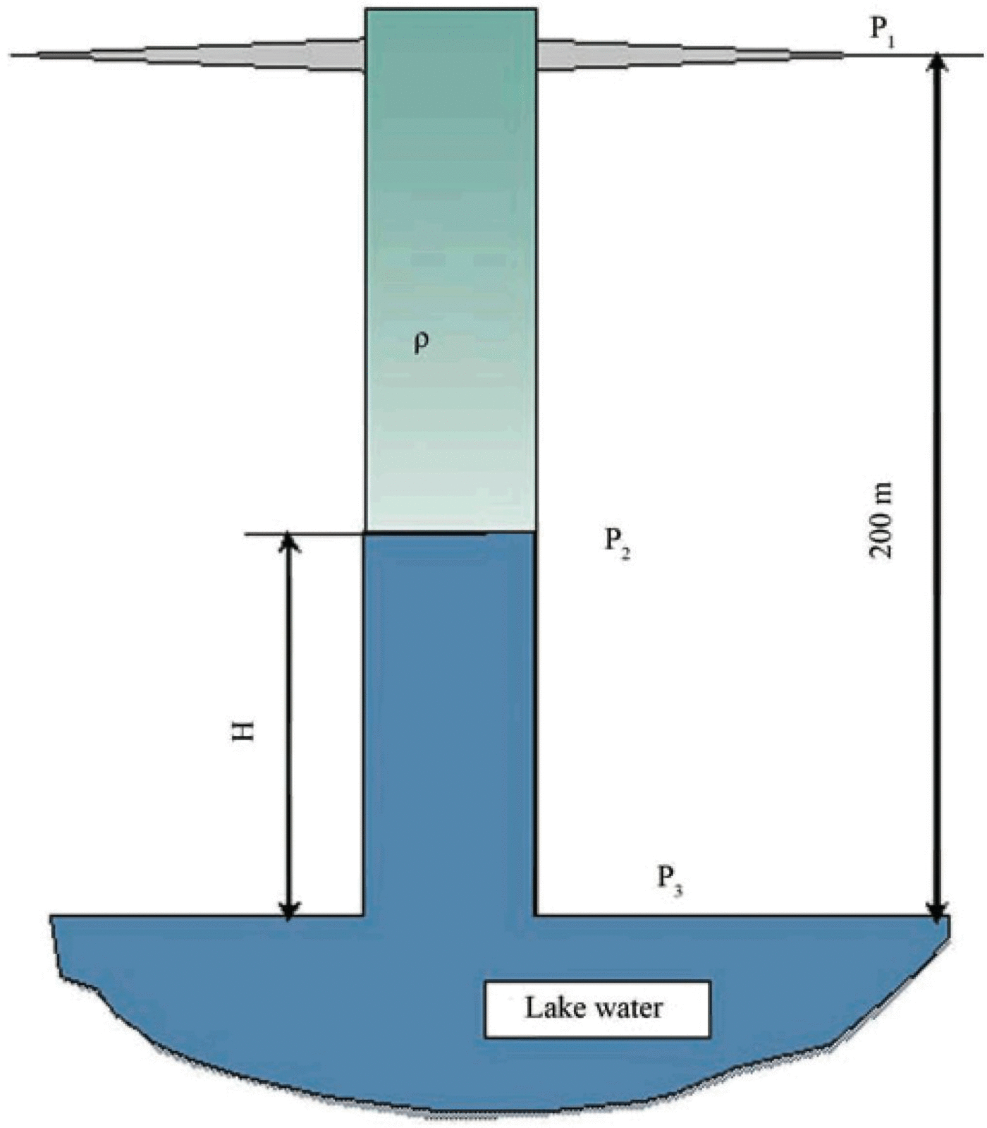
It is reasonable to initiate such hydraulic fracture at a height of not less than 200 m from the lake surface as shown in Figure 2. It should be possible to then regulate the pressure below the hydraulic fracture by adding the weighting agent (Freon® f-141b) to the drilling fluid or changing the average density of this fluid within this borehole segment. This will help set the required height of water level rise.
After completing the seasonal operations of investigation of the lake water layer, the lake water that has risen up the borehole will freeze. This forms a reliable ice cork that separates the lake water strata and the deep borehole filled with the kerosene–Freon1 mixture. The new Environmental Impact Assessment for the aforementioned project was presented by the Russian Federation delegation and approved at CEP XVII in compliance with the adopted procedure of ATCM XXXVII (28 April–7 May 2014, Brazil).
Acknowledgements
We thank the Russiona Antarctic Expedition glacial drilling team and personnel of Vostok station.



