1. Introduction
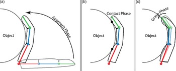
Grasping and manipulation pose one of the most complex challenges in robotics. Therefore, in the present study, humanoid hand-type gripper is chosen over simpler grippers which have lesser degrees of freedom (DoFs) in their fingers/jaws, so that small objects can be grasped and dexterously manipulated. Grippers in the form of a humanoid hand have the advantage of being very articulate end effectors. Due to the multiple DoFs available in the fingers, they can easily adapt to hold objects of complex shapes securely. They can also be easily utilized to perform various types of grasps, such as pinch and power grasps. As a matter of consequence, grasping an object with the appropriate type of grasp can lead to the utilization of a lesser number of fingers. Also, such grippers have redundant DoFs in their fingers which is one of the major advantages over simple grippers. Redundancy resolution in such fingers offers opportunities for singularity avoidance, as well as trajectory optimization by the implementation of the proper performance criteria. Based on the findings and definitions of studies detailing human hand behaviors and the complexity of robotic grasping, the object manipulation by humanoid hand in the present study has been divided into three phases: I. the ‘Approach’ phase, II. the ‘Contact’ phase, and III. the ‘Grasp’ phase [Reference Gardner, Babu, Reitzen, Ghosh, Brown, Chen, Hall, Herzlinger, Kohlenstein and Ro1, Reference Zhang, Xie, Zhou, Wang and Zhang2]. The time between the start of finger motion and the instant before contact is the Approach phase. The instant at which the links come in contact with the object is the Contact phase, and it is followed by the Grasp phase that exists until the object is held securely by the gripper. Figure 1 shows a finger going through the various phases of grasping an object, with each phase highlighted. It is to be noted that the Contact phase is assumed to exist for only a single instant, since it is considered as a Transition phase. However, the Contact phase is the most important phase, as it deals with the transition between the Approach and Grasp phases. The joint configuration of the fingers at the Contact phase will decide their joint-space trajectories in both the Approach and Grasp phases. Depending on the number of contact points, each finger considers a different inverse kinematics (IK) algorithm, which is described in later sections.
Schematic representation of a finger-object interaction during various phases of a grasp.

In the present study, the total energy required by all the fingers of a gripper to firmly grasp an object during the Grasp phase has been termed as ‘Grasp Energy’, which is to be minimized using optimization techniques by selecting optimal contact parameters. The contact parameters have been determined based on the nonlinear spring and damper contact model. The study also takes into consideration Marhefka and Orin’s compliant contact model [Reference Marhefka and Orin3] and the static friction pyramid [Reference Fan-Tien and Orin4] to determine the normal contact forces and the frictional forces, respectively. The optimal contact parameters are used to generate the Grasp phase and Approach phase trajectories. Thereafter, the trajectory requiring the minimum total torque is selected. The assumptions in the present study are as follows:
-
1. Each robotic finger is treated as an independent serial articulated mechanism.
-
2. All the links of the finger and the grasping object are rigid except at the point of contact where there is compliancy.
-
3. All colliding surfaces are nonconforming with respect to each other.
-
4. Each link of a finger contacts the object at a single point.
-
5. No rebound on impact.
-
6. The object coordinates and orientation are invariant, with respect to the world fixed reference frame, during the entire grasp.
The paper is organized as follows: Section 2 includes a brief overview of the previous studies. Section 3 gives a brief description of the anatomy of the human hand. Next, the IK for the Contact phase is derived in Section 4 followed by Grasp-Energy optimization modeling in Section 5. Using the derivations carried out in Sections 4 and 5, the inverse kinematic trajectory generation for the Grasp and Approach phases is detailed in Section 6. Simulation results and comparison with MSC.ADAMS
 $^{\circledR}$
data are stated and discussed in Section 7 with some conclusions drawn in Section 8.
2. Review of Previous Work
One of the major challenges in designing an articulated mechanism targeting object grasp is the optimization of its motion using a desirable performance index. Each approach to optimization uniquely depends on the application itself and the number of allied parameters taken into account.
In redundant manipulators, where the degrees of freedom in the task space are lesser than those in the joint space, the inverse kinematic (IK) equations for a given task space position and/or orientation can have an infinite number of solutions. Suh and Hollerbach [Reference Ki and Hollerbach5], worked on an algorithm, optimizing the inverse kinematic solution using the dynamic manipulability index. The result of such a kinematic resolution was later minimized using null-space damping, as presented by Kang and Freeman [Reference Kang and Freeman6]. They used local torque optimization methods that are usually computationally faster than global optimization methods, but may lead to compounding errors over many time steps as studied by Hollerbach and Suh [Reference Hollerbach and Ki7]. Dubey et al. [Reference Dubey, Euler and Babcock8] used a ‘desired velocity’ vector for optimizing the motion of a 7-DoF robotic arm with spherical wrist, using the gradient projection method which was a local optimization method. Tsai and Kohli [Reference Tsai and Kohli9] proposed a kinematic scheme for planning manipulator trajectory, based on the polynomial expansions of forward kinematic equations. Gorce et al. [Reference Gorce, Villard and Fontaine10] described a control/command approach for multifinger mechanisms, where low-level and high-level commands were implemented together, to control the fingers of a multifingered gripper. Bakhy [Reference Bakhy11] mathematically modeled the contact pressure distribution at contact zone with hemi-cylindrical fingers with rolling contact constraints. Jeong et al. [Reference Jeong, Jo and Bae12] mapped the force distribution between fingers for common grasps, using a film-type force sensor. Jo and Bae [Reference Jo and Bae13] later used the data to design an exoskeleton, driven by series elastic actuators.
The two-norm of manipulator torques is an important performance measure for local torque optimization methods. Kang [Reference Kang14] used this measure to derive the equations for optimal force and joint torque distribution among multiple redundant manipulators holding the same object. One limitation of this optimization scheme was that the author only considered equality constraints, similar to that carried out by Kang and Freeman [Reference Kang and Freeman6] (static equlibrium between joint torques and external forces) to derive the force distribution equations, using Lagrangian multipliers. Cheng and Orin [Reference Fan-Tien and Orin4] proposed a formulation for optimizing force distribution using linearized friction constraints. Inequality constraints, namely the geometric constraints for joint motion, were later incorporated by Zhang et al. [Reference Zhang, Ge and Lee15]. However, the authors only utilized kinematic inequality constraints to solve the optimization problem.
In another method, it was observed that optimizing joint torques for multiple coordinating articulated serial mechanisms involves selection of an optimal external force vector acting on the manipulator. Based on that, Klein and Kittivatcharapong [Reference Klein and Kittivatcharapong16] used the gradient projection method to determine the optimal force distribution for each leg of a legged/walking robot, subject to friction-cone constraints. Buss et al. [Reference Buss, Hashimoto and Moore17] further used this method for optimization of the grasp force matrix, to balance the force of an external object grasped by a N-fingered hand. Dai and Kerr [Reference Dai and Kerr18] proposed analyzing indeterminate grasps by utilizing elasticity constraints at contact points to determine the force distribution among the fingers performing the grasp. Suhaib et al. [Reference Suhaib, Khan and Mukherjee19] followed a more geometric approach for grasp force optimization by identifying various grasp planes to maximize the friction cone angle. However, it was an unconstrained optimization technique. Jia et al. [Reference Jia, li Li, Wang and Li20] used the volumes of the generalized external and internal contact force ellipsoids to establish an optimal grasp planning method.
Further studies dealt with optimizing the grasp configuration itself. Yu et al. [Reference Yong Yu21] worked on a procedure for determining the optimal power grasp form, given a set of known contact points. Horowitz and Burdick [Reference Horowitz and Burdick22] presented an algorithm for treating the tasks of arm trajectory planning, grasp planning, contact force optimization, and object manipulation as a single problem. Dong et al. [Reference Dong, Asadi, Qiu, Dai and Chen23] analyzed the grasp stability of precision grasps, using a force-form based analysis, to optimize the design of an underactuated two-finger gripper. Fan and Tomizuka [Reference Fan and Tomizuka24] introduced a grasp planning framework that used multidimensional surface fitting and a corresponding grasp trajectory optimization algorithm for grasping complex objects.
Many authors opted for optimization in the design stage itself, to obtain better performance of the developed robotic grippers. Müller et al. [Reference Müller, Aydemir, Glodde and Dietrich25] describe several approaches for the design of a soft robotic gripper including selection of the appropriate model for characterization of the maximum payload on the gripper, material characterization, and simulation of grasp to determine its performance at various loads. Kim et al. [Reference Kim, Li and Lee26] developed a Deep-Neural-Network-based algorithm to identify optimal grasping points based on an object’s geometric features for obtaining a stable grasp. Researchers from the University of Brazil developed an anthropometric robotic hand gripper, the UnB-Hand [Reference Pertuz, Llanos and Munoz27], which was designed with bio-inspired optimization algorithms, and was proven to be able to successfully perform grasps according to the Cutkosky grasping taxonomy, that is, power and precision grasps necessary for machining operations. Elangovan et al. [Reference Elangovan, Gerez, Gao and Liarokapis28] proposed a novel adaptive gripper that can adjust link dimensions and finger base positions depending on the surface of the grasped object post contact, to give a more stable grasp.
Although the problem of grasp planning has been solved by numerous methods, the formalization of procedures to determine the success of a grasp, as reported by Acuetino-Cabezas et al. [Reference Aceituno-Cabezas, Ballester and Rodriguez29], is not comprehensive. The authors studied and determined conditions that could guarantee the success of a two-dimensional grasp, and hence be able to validate any proposed grasp planning procedure. Similarly, Yan et al. [Reference Yan, Deng, Chen, Nie and Zhang30] used a four-finger tendon-driven robot hand, to demonstrate a method for analyzing the manipulation capabilities of a given prosthetic/robotic hand. Singh and Ambike [Reference Singh and Ambike31] also presented two metrics: grasp caliber and grasp intensity, to quantitatively decide the stability of a grasp. Dong et al. [Reference Dong, Qiu, Prasad, Pan, Dai and Chen32] explored the evaluation of grasping quality, by constructing a model of grasp stiffness. This study is also a motivating factor in the development of the contact dynamics model in the present study.
It is to be noted that although there are many algorithms available for minimizing joint torques or calculating optimal contact force distribution during object grasp, most of the studies are typically restricted to hard point contact between rigid bodies [Reference Buss, Hashimoto and Moore17, Reference Dong, Asadi, Qiu, Dai and Chen23, Reference Mirza and Grin33–Reference Yao, Ceccarelli, Carbone and Dong36] with few investigations in recent past on soft robotics [Reference Schmitt, Piccin, Barbé and Bayle37]. However, the investigations reconciling Hertz’s contact stress theory with deformable gripper behavior are not comprehensive. Moreover, there are limited studies reporting on the optimal distribution of contact forces and joint torques for a five-fingered, twenty-DoF humanoid robotic hand during object grasp, based on compliant contact (that is, nonlinear spring and damper system), using an energy-based optimization algorithm.
The present study addresses these issues through a novel grasp optimization algorithm, utilizing an energy-based objective function to minimize the net energy required to execute a grasp, taking advantage of redundant DoFs available in a gripper’s fingers. The present study also describes a novel approach to instantaneous IK for determining the desirable joint trajectories when multiple contact points are present on the same finger. Hence, to the best of the author’s knowledge, the present study of a grasp optimization technique with an objective function derived directly from the theory of compliant grasps, as well as, an IK algorithm to accommodate multiple end effectors on a single serial manipulator has not been attempted before. Although, the optimization algorithm has been developed for a twenty DoF humanoid hand with five fingers (allowing four DoFs in each finger), it can be easily adapted to other types of grippers with redundant DoFs available in their fingers.
3. Anatomical Description of the Hand
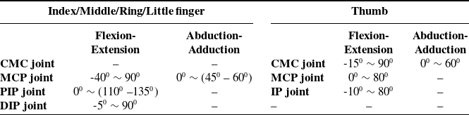
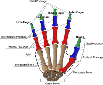
Figure 2 shows the anatomical diagram of the human hand. The robotic humanoid hand gripper used in this study is modeled closely from the anatomical structure of the hand. The index, middle, ring, and little fingers have three movable bones: the proximal, intermediate, and distal phalanges. The proximal phalange of each finger is connected to the palm by a metacarpophalangeal (MCP) joint, which allows two DoFs, one for flexion/extension motion and the other for abduction/adduction motion [Reference Kapandji38]. The remaining two joints, the proximal interphalangeal (PIP) and distal interphalangeal (DIP) joints, allow one DoF of motion, namely, flexion/extension. In the thumb, the metacarpal bone is connected to the wrist bones (carpal bones) by the carpometacarpal (CMC) joint, which allows two DoFs of motion. The remaining two joints, that is, the MCP and the interphalangeal (IP) joints, allow one DoF of motion, flexion/extension. Thus, each finger has four DoFs of motion, thereby giving a sum total of twenty DoFs for the five-fingered hand. Table I shows the ranges of motion allowed by each joint of each finger, when measured with respect to a fully extended/relaxed position of each finger.
Ranges of motion of each joint of the hand (in degrees) [Reference Cobos, Ferre, Sanchez Uran, Ortego and Pena39].

Anatomical diagram of the human hand.

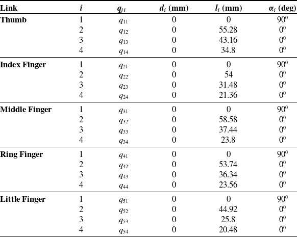
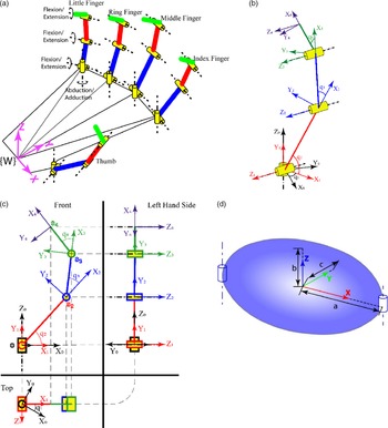
In the present study, a simplified schematic representation of the human hand and fingers with assigned reference frames, kinematic link lengths, and joint angles have been constructed as shown in Fig. 3(a). Figures 3(b) and 3(c) show the generalized schematic diagram of a finger with reference frames assigned. Further, the classical Denavit–Hartenberg (DH) convention [Reference Spong, Hutchinson and Vidyasagar40] has been followed while deriving the kinematic model of the hand. The DH parameters used, for each link of the hand are enlisted in Table II.
DH parameters of the five fingered Anthropometric robotic hand.

 ${q_{ji}}$
= Generalized joint coordinate of frame
 $\{ i\} $
with respect to frame
 $\{ i - 1\} $
for finger
 $j$
.
 ${l_i}$
= Length of link
 $i$
, between the
 ${Z_i}$
and
 ${Z_{i - 1}}$
axes, along the
 ${X_{i - 1}}$
axis for finger j.
 ${\alpha _i}$
= Angular twist given to link
 $i$
, measured between
 ${Z_i}$
and
 ${Z_{i - 1}}$
axes, about the
 ${X_{i - 1}}$
axis for finger j.
 ${d_i}$
= Joint offset given to link
 $i$
, measured between
 ${X_{i - 1}}$
and
 ${X_i}$
, along the
 ${Z_{i - 1}}$
axis for finger j.
Here,
 ${q_i}$
is the angle of a revolute joint, attached at the base of link i of finger j, measured between
 ${X_i}$
and
 ${X_{i - 1}}$
axes, about the
 ${Z_{i - 1}}$
axis.
The frames are attached at


Schematic representation with reference frames, (a) 20-DoF hand, (b) three-dimensional (3D) view of a finger, (c) two-dimensional (2D) projections of a finger, (d) ellipsoidal geometry of a finger phalange.

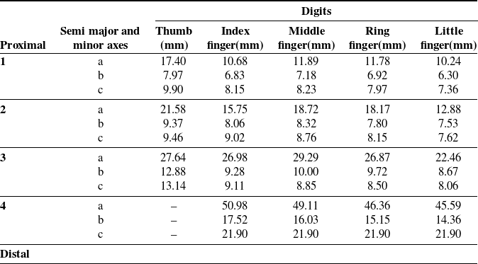
Anthropometric dimensions of fingers using ellipsoidal geometry.

4. Contact Phase Inverse Kinematics
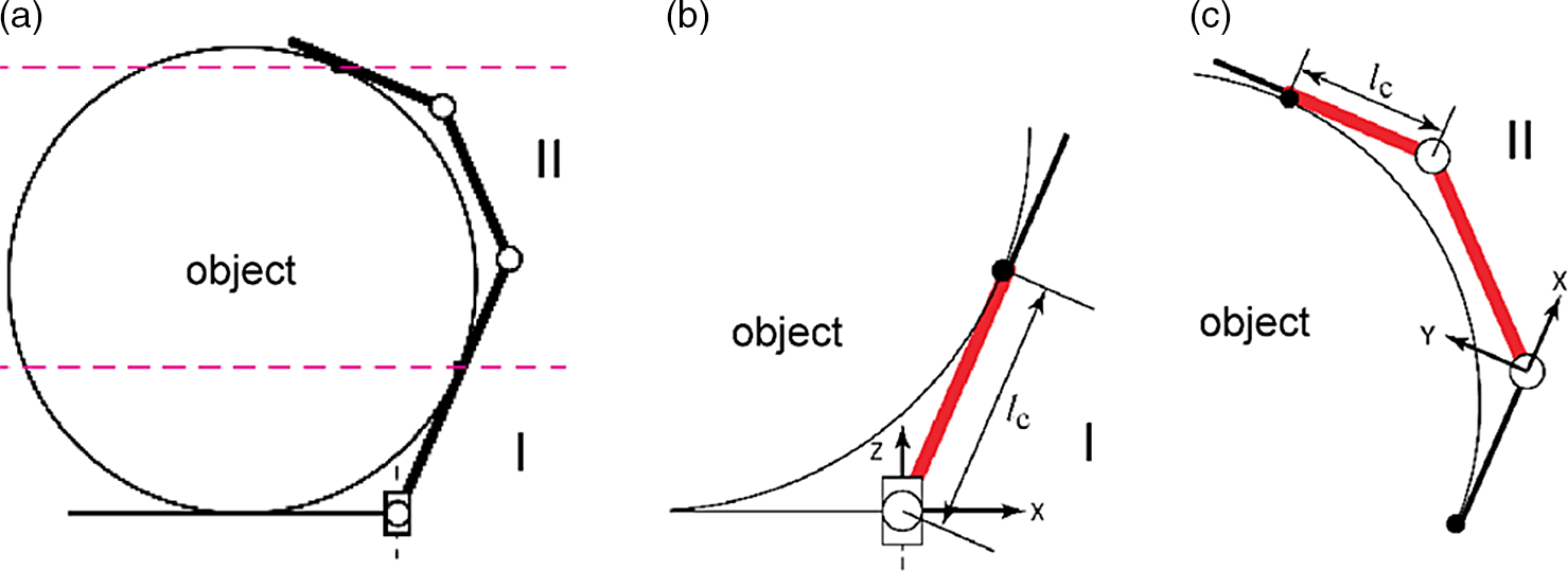
The Contact phase is the most important phase of a grasp, due to its transitional nature. The Contact phase indicates the end of the Approach phase and start of the Grasp phase. The objective is to determine the joint configuration of the finger at the instant of contact, given that the coordinates of the point/points of contact between the finger and the object are known. Generally, IK algorithms deal with a single end effector, reaching a single target coordinate. However, a finger can contact the object at multiple points, creating multiple target coordinates. The method of IK described in this section uses the sub-manipulator ideology to determine the joint configuration [Reference Xu, Mu, Liu and Liang44–Reference Roy, Mukherjee, Das and Bhaumik47].
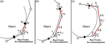
Figure 4 gives an illustration of a finger divided into sub-manipulators, at the time of multiple points of contact between the finger and the object. The advantage of this method lies in the fact that, instead of solving for a finger with L
j
contact points, the problem is simplified into solving the IK for L
j
sub-manipulators where L
j
is the total number of contact points on the jth finger. For this study, there can be a maximum of three contact points between the finger and the object, thus
 ${L_{{j_{max}}}} = 3$
.
Illustration to show the division of sub-manipulators, (a) manipulator grasping an object, (b) I: 2-DoFs spatial sub-manipulator, (c) II: 2-DoFs planar sub-manipulator.

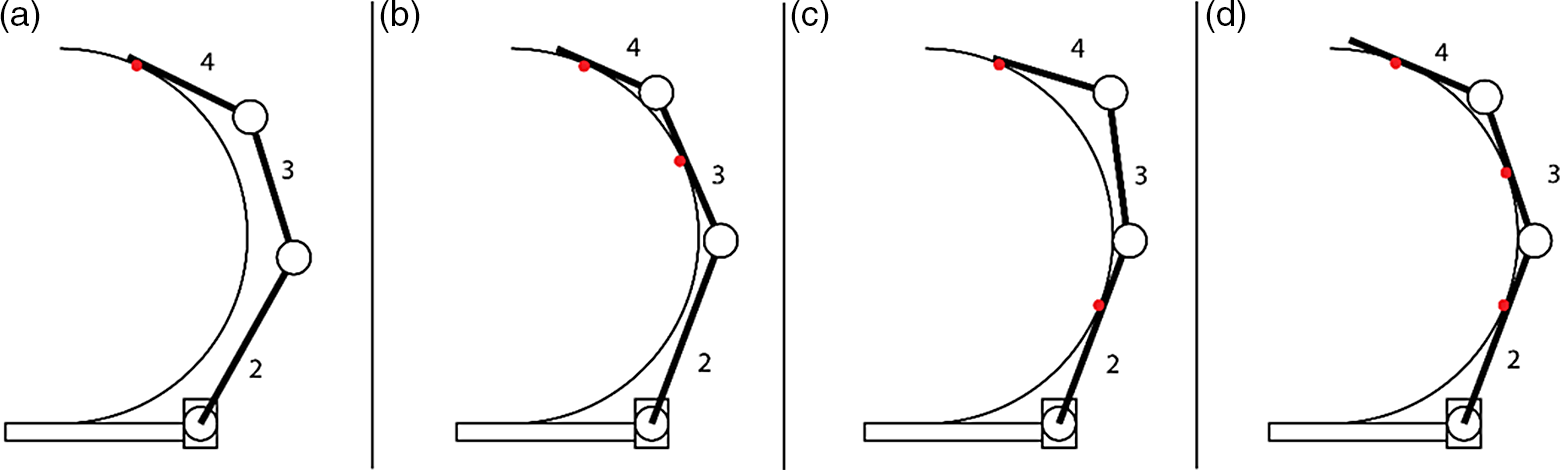
Figure 5 shows the various possible contact configurations between any given finger and the object. Figure 5(a) shows a precision grasp, while Figs. 5(b), 5(c) and 5(d) show power grasps [Reference Feix, Romero, Schmiedmayer, Dollar and Kragic48]. From Fig. 5, it can be concluded that the finger can form four types of sub-manipulators, depending on the configuration of contact, a 1-DoF sub-manipulator, a 2-DoF sub-manipulator, a 3-DoF sub-manipulator, and a 4-DoF sub-manipulator, which is essentially the entire finger.
Various configuration mode of a finger and object during contact, (a) one contact point (4-DoF sub-manipulator with links 2,3,4), (b) two contact points (3-DoF sub-manipulator with links 2, 3 and 1-DoF sub manipulator with link 4), (c) two contact points (2-DoF sub-manipulator with link 2 and 2-DoF sub manipulator with link 3, 4), (d) three contact points (2-DoF sub-manipulator with link 2, 1-DoF sub manipulator with link 3 and 1-DoF sub manipulator with link 4).

Figure 6(a) illustrates the kinematic aspect of the interaction between the finger and the object. The length l c is termed as the contact length and is used to determine the Jacobian matrix between the point of contact and the base frame of the sub-manipulator [Reference Mukherjee and Mahapatra49]. To determine the joint configuration of the complete finger, each sub-manipulator is analyzed one after the other. The solution from the sub-manipulator formed for the first contact point is used to determine the position of the base frame of the next sub-manipulator, and so on. The base point of the first sub-manipulator of any finger will always be the abduction/adduction joint of the finger (CMC joint for the thumb and MCP joint for the rest).
Schematic representation of, (a) interaction between the finger and object with end-effector point P (in the finger) contacting the object at a point P′, (b) interaction between two colliding bodies with the position of the local reference frame.

The joint angle/configuration of the base joint of the first sub-manipulator of any finger can be determined as
 $${({q_1})_j} = {\rm{atan}}2({\{ {y_P}\} _0},{\{ {x_P}\} _0}),$$
where
 $${({q_1})_j}$$
is the abduction/adduction (or the base joint) angle of the jth finger, {x
P}0 and {y
P}0 are the x and y coordinates of the first contact point ‘P’ measured with respect to frame {0} (or the base frame) of the finger. Fixing the abduction/adduction angle (joint angle of the base joint) fixes the flexion/extension plane as well. Hence, once the base joint angle is calculated using Eq. (1), all the sub-manipulators can be treated as planar in nature. As a result, the IK of the first sub-manipulator can be solved by simply reducing its initial DoFs by 1. The end of the link contacting the object is assumed to be the base for the next consecutive sub-manipulator.
Figure 7(a) shows the general depiction of a 1-DoF sub-manipulator followed by a 2-DoF sub-manipulator shown in Fig. 7(b) and a 3-DoF sub-manipulator shown in Fig. 7(c). Only planar cases have been considered, due to the reasons mentioned above. Based on Fig. 7(a), the joint angle for a 1-DoF sub-manipulator can be easily calculated as
 $${({q_i})_j} = {\rm{atan2}}\left( {{{\left\{ {{y_{{{S'}_1}}}} \right\}}_{i - 1}},{{\left\{ {{x_{{{S'}_1}}}} \right\}}_{i - 1}}} \right)$$
where
 ${({q_i})_j}$
is the ith joint angle of the sub-manipulator of the jth finger;
 ${{{\left\{ {{x_{{{S'}_1}}}} \right\}}_{i - 1}}}$
and
 ${{{\left\{ {{y_{{{S'}_1}}}} \right\}}_{i - 1}}}$
are the x and y coordinates of the contact point
 ${S{\kern1pt'}_{\!\!1}}$
for the 1-DoF manipulator, measured in the frame
 $\{ i - 1\} $
. Here, link/joint number
 $i$
refers to the end-effector link of the sub-manipulator. The preceding links are numbered as
 $i - 1$
and
 $i - 2$
, as shown in Figs. 7(b) and 7(c).
Illustration of various types of sub-manipulators, (a) 1-DoF sub-manipulator, (b) 2-DoF sub-manipulator, (c) 3-DoF sub-manipulator.

Similarly, the joint angles for a 2-Dof sub-manipulator (refer to Fig. 7(b)) are given by
 $${({q_{i - 1}})_j} = {\rm{asin}}\left( {{{l_{i - 1}^2 - l_c^2 + \left\{ {{x_{{{S'}_2}}}} \right\}_{i - 2}^2 + \left\{ {{y_{{{S'}_2}}}} \right\}_{i - 2}^2} \over {2{l_{i - 1}}\sqrt {\left\{ {{x_{{{S'}_2}}}} \right\}_{i - 2}^2 + \left\{ {{y_{{{S'}_2}}}} \right\}_{i - 2}^2} }}} \right) - {\rm{atan2}}\left( {{{\left\{ {{x_{{{S'}_2}}}} \right\}}_{i - 2}},{{\left\{ {{y_{{{S'}_2}}}} \right\}}_{i - 2}}} \right),$$
 $${({q_i})_j} = {\rm{asin}}\left( {{{{{\left\{ {{y_{{{S'}_2}}}} \right\}}_{i - 2}}\cos ({q_{i - 1}}) - {{\left\{ {{x_{{{S'}_2}}}} \right\}}_{i - 2}}\sin ({q_{i - 1}})} \over {{l_i}}}} \right).$$
where
 ${q_i}$
and
 ${q_{i - 1}}$
are the joint angles of the 2-DoF sub-manipulator and l
i
is the length of the ith link. The contact length l
c
can be determined from the MSC.Adams
 $^{\circledR}$
simulation.
Again, for a 3-DoF planar sub-manipulator, the redundant DoF does not allow for a closed-form solution. Hence, the possible solutions are determined by fixing the base joint angle and solving the IK problem for the remaining two links as a 2-DoF sub-manipulator (refer to Eqs. (3a) and (3b)). Multiple such base-joint angles are considered between an interval of ±3°, based on the original Contact phase configuration determined from the MSC.Adams
 $^{\circledR}$
simulation.
5. Grasp-Energy-based Optimization
5.1. Hand and object interaction modeling
As previously mentioned, the contact dynamics in this study follows the Hertzian contact stress theory. The normal force on contact, F n , is calculated using a modified Hunt and Crossley non-linear spring-damper model presented by Marhefka and Orin [Reference Marhefka and Orin3, Reference Hunt and Crossley50] and is given by
 $${F_n} = {\rm{ (}}\lambda {\delta ^\rho })\dot \delta + K{\delta ^\rho },$$
where
 $K$
is the contact stiffness;
 $\lambda $
is the damping co-efficient;
 $\delta $
gives the penetration depth, that is, the total distance between A and A′ as shown in Fig. 6(b);
 $\dot \delta $
gives the relative penetration velocity of body 1 with respect to body 2, along the local contact frame
 $\hat{Z}$
-axis and
 $ho $
is the contact exponent. In the present study,
 $ho $
is set equal to 1.5, assuming nonconforming contacts [Reference Marhefka and Orin3, Reference Johnson51].
Also, assuming no-slip conditions, the friction force along each axis is calculated as
 ${f_x},{f_y} \le {\rm{ |}}\mu {F_n}|,$
where
 ${f_x}$
is the friction force along the
 $\hat{X}$
-axis and
 ${f_y}$
is the friction force along the
 $\hat{Y}$
-axis. It is to be noted that Eqs. (4) and (5) have been represented in a local frame of reference, placed at the point of contact, as shown in Fig. 6(b). Normal force at contact, F
n
, points along the +
 $\hat{Z}$
-axis of the local reference frame, that is, into the object 1. The X-Y plane lies parallel to the osculating plane CC′ containing the point of contact, and the
 $\hat{Z}$
-axis is directed toward the object and lies along the normal to the contacting surfaces or osculating plane at the point of contact. Assuming that the torque acting at the point of contact is negligible, the force-torque wrench vector in the local frame of the ith contact point can be defined as
 $${{\rm{(}}{h_e})_i} = \;{({f_x}\;,{f_y}\;,{F_n})^T},$$
and the vector
 ${{\rm{(}}{h_e})_i}$
can be transformed [Reference Craig52] to a new frame {k} as
 ${{\rm{(}}{h_e})_k} = _k^i{R^ * }{{\rm{(}}{h_e})_i},$
where
 ${}_k^iR$
is the rotational transform of frame {k} with respect to frame {i}.
5.2. Objective function
Successful execution of a grasp depends on the invariance of the object coordinates within its configuration space [Reference Aceituno-Cabezas, Ballester and Rodriguez29]. The grasps described in this study assume force-closure conditions, to ensure stable grasps [Reference Svinin, Ueda and Kaneko53, Reference Xiong, Sanger and Kerr54]. Using this concept as the primary constraint, and the fact that the contact mechanics has been modeled using the principles of compliant contact between objects, an energy-based optimization performance measure has been formulated, and termed as Grasp-Energy.
The objective function has been derived using the principles of virtual work. In static friction conditions, penetration progressess only along the
 $\hat{Z}$
-axis of the local contact-point coordinate frame. Hence, the instantaneous work done (dW) can be written as
 \begin{align} {{d}}W = {F_n} \cdot {m{d}}\delta + d{F_n} \cdot \unicode[Times]{x03B4}. \end{align}
As the work done at any instant during collision depends on the amount of penetration, then for an incremental change in penetration depth,
 ${{d}}\delta $
the work done will be
 \begin{align} \frac{{{{d}}W}}{{{{d}}\delta }} = {F_n} + \frac{{{{d}}{F_n}}}{{{{d}}\delta }}\delta . \end{align}
Substituting Eq. (4) in Eq. (9) and differentiating the expression reduces to
 $${{dW} \over {d\delta }} = {\rm{ (}}\rho + 1){\rm{(}}\lambda \dot \delta + K){\delta ^\rho }$$
The net work done or the net energy consumed, between the time of impact t I and time of completion of grasp t F , can thus be obtained as
 $$G{E_{ji}} = {\rm{ }}\int\limits_{t = {t_1}}^{tF} {(\rho + 1)} {\rm{ (}}\lambda \dot \delta + K){\delta ^\rho }{\rm{d}}t,$$
where GE ji represents the Grasp-Energy required at the ith contact point of the jth finger.
The total Grasp Energy of the hand can be summed numerically across all contact points of all fingers and is given by
 \begin{align} GE = \mathop \sum \limits_{j = 1}^N \mathop \sum \limits_{i = 1}^{{L_j}} G{E_{ji}} \end{align}
Here, N gives the total number of fingers contacting the object and L j gives the total number of points of contact on the jth finger. Therefore, minimizing Eq. (12) subject to equality and inequality constraints is the objective of the optimization problem.
5.3. Constraint Definitions
The derivation and subsequent optimization of the objective function is subject to certain assumptions:
-
1. The surface of the object being grasped is convex, that is, facing away from the center of the object at the points of contact.
-
2. The surface of the object is continuous and differentiable at the point of contact.
-
3. The links of the fingers that collide with the object, do so simultaneously at the same time of impact.
Now, based on the above assumptions, the following constraints are applied on the objective function:
-
a) Geometric constraints: The geometric constraints define the bounds of the design variables
 $\delta $
,
$\dot \delta $
and instantaneous penetration acceleration
$\ddot \delta $
and is given by


 \begin{align} 0 \le \delta \le {\delta _{max}}, \end{align}
 \begin{align} 0 \le \dot \delta \le {\dot \delta _I} \le {\dot \delta _{max}}, \end{align}
 $$ - {\rm{|}}{{\ddot \delta }_{max}}| \le \ddot \delta {\rm{ < }}0,$$
where
 ${\delta _{max}}$
gives the maximum allowable penetration depth, based on the object’s and fingers’ mechanical properties;
 ${\dot \delta _I}$
is the velocity of link at impact;
 ${\dot \delta _{max}}$
gives the maximum allowable penetration velocity based on the allowable joint actuation velocities, and
 ${\rm{|}}{{\ddot \delta }_{max}}|$
gives the magnitude of the maximum allowable penetration acceleration, depending on the capabilities of the actuators used. The penetration acceleration must always be negative, once the fingers come into contact with the object, in order to decelerate the fingers after impact.
-
b) Allowable time of impact: The bounds on the allowable times of impact are set by this constraint, such that
 \begin{align} 0 \lt {t_{{I_{min}}}} \le {t_I} \le {t_{{I_{max}}}} \lt {t_F}. \end{align}
where
 ${t_{{I_{min}}}}$
gives the minimum allowable time of impact,
 ${t_{{I_{max}}}}$
gives the maximum allowable time of impact, t
F
is the pre-set time of completion of grasp, and t
I
is the selected time of impact for optimization. It is to be noted that at t = t
F
, the generated net contact force vector is intended to create static equilibrium conditions for the object being grasped.
-
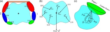
c) Static equilibrium equation: The static equilibrium constraint fulfills the condition of invariance of object coordinates, by constraining the optimal solution set to maintain the object’s static equilibrium, at the end of the grasp (refer to Fig. 8).
The static equilibrium equation is given by
 $${\left\{ {\sum\limits_{j = 1}^N {\sum\limits_{i = 1}^{{L_j}} {{{\vec h}_{{e_{ji}}}}} } } \right\}_{t = {t_F}}} + {\overrightarrow F _e} = 0.$$
where
 ${\vec h_{{e_{ji}}}}$
is the vector of net contact force acting on the object at the ith contact point (corresponding to the ith link in contact) of the jth finger ;
 ${\vec{\kern-1pt{F}}_e}$
is the sum of all external force vectors acting on the object. Further, Eq. (15) implies that complete static equilibrium can be achieved only at the time of completion of grasp. It is to be noted that the constraints are set, such that minimum energy is required to precisely grasp the object. Hence, the reaction force of the palm on the object has been neglected in this study (refer to Fig. 8(b)) since its effect is predominant when more force is required to neutralize all the external forces.
-
d) Friction force constraints: The static friction force constraints govern the selection of the force vector. The friction cone constraints generally used in such situations [Reference Fan-Tien and Orin4, Reference Xiong, Sanger and Kerr54] can instead be reduced to a much more conservative set of linear constraints for a friction pyramid (refer to Fig. 8(c)) expressed as
 \begin{align} - f_{ji}^x + \frac{\mu }{{\sqrt 2 }}{F_{{n_{ji}}}} \lt 0, \end{align}
 \begin{align} f_{ji}^x + \frac{\mu }{{\sqrt 2 }}{F_{{n_{ji}}}} \lt 0, \end{align}
 \begin{align} - f_{ji}^y + \frac{\mu }{{\sqrt 2 }}{F_{{n_{ji}}}} \lt 0, \end{align}
 \begin{align} f_{ji}^y + \frac{\mu }{{\sqrt 2 }}{F_{{n_{ji}}}} \lt 0, \end{align}
where
 $f_{ji}^x$
is the force of friction along the X-axis of the local coordinate frame at the point of contact of the ith link of the jth finger,
 $f_{ji}^y$
is the force of friction along the Y-axis of the local coordinate frame at the point of contact at the ith contact point (corresponding to the ith link in contact) of the jth finger, and
 $\mu $
is the coefficient of friction that is assumed to be uniform for all contact points.
Schematic representation, (a) fingers 1 and 2 grasping an object, (b) free-body diagram of the object with forces acting on it during grasp, (c) friction pyramid constraint and friction forces during interaction at the ith contact point of the jth finger with a rigid object.

6. Approach and Grasp Phase Trajectory Generation
6.1. Grasp phase
The possible Grasp phase joint trajectories are calculated taking into consideration both the multiple Contact phase IK solutions as well as the impact penetration velocity and acceleration values determined using the optimization algorithm. Thereafter, the set of Grasp phase joint trajectories that utilizes the least joint torque norm can then be used for determining the Approach phase joint trajectories.
Computation of the optimal values of penetration accelerations for each finger and impact time leads to the determination of the joint trajectory of the fingers for the Grasp phase. Due to the nature of the optimization algorithm, each link contacting the object is assigned an optimal penetration depth, impact velocity, and impact acceleration values. Thus, each sub-manipulator needs to follow the cartesian trajectory assigned to its end effector to achieve an optimal grasp. For this, an algorithm has been developed that uses the method of instantaneous IK for each sub-manipulator, to iteratively calculate the joint configuration of the finger. Assuming that the inverse kinematic solution for a given set of trajectories for a finger exists, the following equations can be used to iteratively calculate the desired joint trajectories, for each sub-manipulator, at a given time step:
-
1. For the first sub-manipulator with m DoFs (including the DoF of the abduction/adduction joint), the joint velocity vector is given by
 $${\left( {\matrix{
{{{\dot q}_1}} \cr
\vdots \cr
{{{\dot q}_i}} \cr } } \right)_{m \times 1}} = {(^0}{J_i})_{i \times {3^ * }}^\# *{{(^0}{V_i})_{3 \times 1}}.$$
-
2. For each subsequent sub-manipulator, the equation to be used is given by
 $${\left( {\matrix{
{{{\dot q}_{i + 1}}} \cr
\vdots \cr
{{{\dot q}_k}} \cr
} } \right)_{(k - i) \times 1}} = {(^0}{J_k})_{(i + 1:k) \times 3}^\# \left[ {{{{(^0}{V_k})}_{3 \times 1}} - {{{(^0}{J_k})}_{(1:m) \times 3}}{{\left( {\matrix{
{{{\dot q}_i}} \cr
\vdots \cr
{{{\dot q}_i}} \cr
} } \right)}_{i \times 1}}} \right],$$
where
 ${\dot{q}_{i}}$
is the joint velocity of the ith joint,
 ${}^{0}{J_{k}}$
is defined as the jacobian matrix for the kth contact point with respect to the base frame of that finger [Reference Mukherjee and Mahapatra49],
 ${}^{0}J_{k}^{\#} $
represents the Damped-Least-Square (DLS) inverse of the Jacobian [Reference Buss55] for the kth contact point, and
 ${}^{0}{V}_{k}$
is the target velocity of the kth contact point. It is also to be noted that, in the present case
 ${{(^0}{J_k})_{(a1:a2) \times b}}$
specifies a submatrix of
 ${}^{0}{J}_{k}$
, consisting of rows a
1 to a
2 and b columns.
Now, using Eqs. (17a) and (17b), the joint velocities at a given time step for a finger are calculated iteratively. The desired joint configuration for the current time step is thus updated and given by
 \begin{align} {q_{current}} = {q_{previous}} + {\dot q_{current}}{}^{\ast}{{\Delta }}t \end{align}
Likewise, the desired motion of all the fingers can be calculated iteratively. Thereafter, the Contact phase configuration with the minimum Grasp phase torque norm is then selected to determine the Approach phase joint trajectory. The joint torques are determined using the dynamic equations of motion [Reference Spong, Hutchinson and Vidyasagar40, Reference Siciliano, Sciavicco, Villani and Oriolo56].
6.2. Approach phase
Using the boundary conditions at the optimal initial time of impact, t I *, along with the Grasp phase joint trajectories’ values, the Approach phase joint trajectories can be easily determined as a time-based polynomial function of fifth order given by
 \begin{align} {q_{ij}} = {a_0} + {a_1}t + {a_2}{t^2} + {a_3}{t^3} + {a_4}{t^4} + {a_5}{t^5} \end{align}
The necessary boundary conditions for determination of the coefficients of the polynomial function during Approach phase are given by
-
(i)
$\;t = 0,{m{\;}}\;\;\;\;{q_{ij}} = 0,\;\;\;\;{\dot q_{ij}} = 0,\;\;\;\;{\ddot q_{ij}} = - \ddot q_{ij}^{^{\ast}}\;,$
at -
(ii) at
$t = t_I^*,\;\;\;\;{q_{ij}} = q_{ij}^{^{\ast}},\;\;\;\;{\dot q_{ij}} = \dot q_{ij}^{^{\ast}},\;\;\;\;{\ddot q_{ij}} = \ddot q_{ij}^{^{\ast}}$
.


The step-wise working of the entire grasp algorithm has been explained in the Appendix.
7. Numerical Illustration
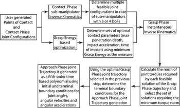
The block diagram shown in Fig. 9 demonstrates the working of the grasp optimization algorithm. After the object has been grasped, interaction forces generated between the object and the fingers at the points of contact (termed as contact forces) are determined, before computation of the joint torques required to secure the grasp. However, it is to be noted that the approach is computationally intensive and carried out offline with the predefined boundary conditions for the determination of a set of optimal force-space configurations.
Block diagram showing various stages of the grasp optimization algorithm.

To demonstrate the efficacy of the developed grasp optimization algorithm, computer simulations are run in MATLAB
 $^{\circledR}$
and compared with simulations using Virtual Prototyping (VP) tools, like the commercially available numerical solver MSC.Adams
 $^{\circledR}$
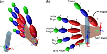
. The coordinates of the points of contact and a desired joint configuration at the Contact phase are required to be given as initial input (refer to Section 6), which are obtained from the simulation model (refer to Fig. 10) in MSC.Adams
 $^{\circledR}$
, with the same boundary conditions. The world reference frame {W} with XwYwZw axes system is fixed at the bottom of the object, as shown in Fig. 10. The subscript ‘bj’ is used to indicate the axes of the base frame of the jth finger. Gravity acts, along the axis of the cylinder, in the –ZW direction.
Reference frames and initial configuration of the robot hand model for precise grasping of a small cylindrical object, (a) Isometric view, (b) Front view.

In the MSC.Adams
 $^{\circledR}$
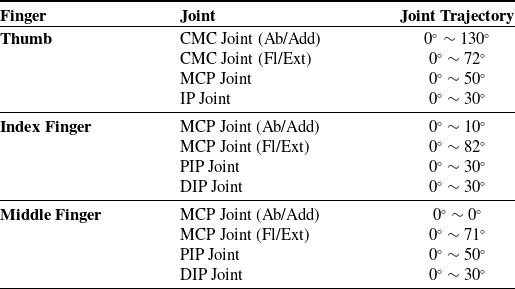
simulation, the object to be grasped is treated as a ground object to fulfill the invariance condition. Predefined joint trajectories are provided to each joint of the three fingers, namely, thumb, index, and middle, as given in Table IV. These grasp trajectories are generated using trial and error method to imitate a user’s action, before it is optimized and passed on to the actual robotic gripper. The coordinates of the points of contact between the gripper and object, obtained from the dynamic simulation in MSC.Adams
 $^{\circledR}$
, are exported to MATLAB, where a numerical simulation of the algorithm is run, using the same boundary conditions.
Input joint trajectory ranges assigned to the hand in MSC.Adams
 $^{\circledR}$
Simulation.

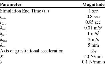
The values of the common boundary conditions chosen for the simulation are given in Table V. In order to determine the desired force-space configuration, a direct grid-search method is adopted, wherein the possible force combinations amongst all contact points are evaluated, to test whether a configuration satisfies all constraints. Due to the limitation of using a grid-search algorithm, the possible forces within the force pyramid of each contact point are discretized. As a result of the discretization of forces, it is difficult to obtain a force-space configuration that can completely balance out the external forces acting on the object. Hence, in order to satisfy the equilibrium constraint, a maximum limit on the allowable net force (the sum of all contact forces and external forces) is set for the case study. Any force-space configuration whose sum of the external forces lay below the allowable limit is selected to check if the vectors further satisfied the remaining constraints. Due to this, the total number of contact points between the hand and the object has been restricted to three, that is, a precision grasp is chosen for the demonstration. The hand motion is simulated to grasp a solid cylinder (similar to grasping a pen/pencil’s stem), with three fingers, namely, the thumb, the index finger, and the middle finger as mentioned in Table IV. However, it is to be noted that the angular displacement of the CMC joint (abduction/adduction joint) of the thumb (approximately, 130°) is large and has been provided as input to the joint trajectory in MSC.Adams
 $^{\circledR}$
simulation (refer to Table IV). This angle is beyond the ranges of motion described for a human hand in Table I, and therefore, it perfectly encompasses the limitations of a simplified humanoid hand model.
Common input parameters for the case study.

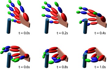
The actual human hand is a complex structure, and a robotic model of the hand can only imitate the human in an approximate manner. Hence, such a large abduction/adduction motion has been assigned to the thumb since it is necessary for the proper execution of its opposition motion in the constraints of the developed model. Snapshots of the hand motion sequence at regular intervals of the simulation are shown in Fig. 11.
Snapshots of the robot hand motion for grasping a small object (cylinder) simulated in MSC.Adams
 $^{\circledR}$
.

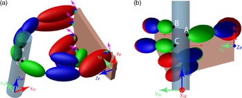
At the end of simulation, three points of contact are obtained, as shown in Fig. 12. Since the object is grasped with the tips of each finger, three 4-DoF sub-manipulators are formed. Using the IK algorithm described in Section 4, the first joint angle is calculated, thereby reducing the problem into a 3-DoF planar sub-manipulator whose base angle is the second joint of the finger. The angle base joint of the 3-DoF sub-manipulator is fixed at various points within ±3° of the initial configuration at contact, and the IK solution for the remaining two links is determined for each value of the base joint angle. The set of contact points (C
P
) obtained from the MSC.Adams
 $^{\circledR}$
simulation (dimensions are in millimeters) is given by
 $${C_P} = {\rm{ }}{\left( {\matrix{
{{x_A}\;\;\;\;\;{x_B}\;\;\;\;\;{x_C}} \cr
{{y_A}\;\;\;\;\;{y_B}\;\;\;\;\;{y_C}} \cr
{{z_A}\;\;\;\;\;{z_B}\;\;\;\;\;{z_C}} \cr
} } \right)_{W}} = {\rm{ }}\left( {\matrix{
{ - 2.6\;\;\;\;\;4.7\;\;\;\;\;1.7} \cr
{ - 9.6\;\;\;\;\;8.8\;\;\;\;\;9.7} \cr
{61.5\;\;\;\;\;71.0\;\;\;\;\;50.0} \cr
} } \right)$$
Position of the robot hand model and location of the three points of contact after completion of grasp (at t = 1.0s), (a) Isometric view, (b) Front view. The ring finger and little finger follow independent joint trajectories, to make it look similar to an actual precision grasp.

The total Grasp Energy is calculated as 73.6 N-mm using the simulated data from MSC.Adams
 $^{\circledR}$
as shown in Fig 13. The boundary conditions, Contact phase joint configurations, and coordinates of points of contact obtained from MSC.Adams
 $^{\circledR}$
simulation are provided as input to the analytical model simulated in MATLAB. The cartesian coordinates of the points of contact and the possible joint configurations at the Contact phase are supplied as input to the optimization algorithm run in MATLAB. The output data are post processed, and the trajectory with the minimum net Grasp Energy is selected, which has a value of 55.9 N-mm.
Simulated data of the points of contact in MSC.Adams
 $^{\circledR}$
, (a) the normal force distribution, (b) the penetration depth profile.

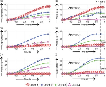
Figure 14 compares the joint trajectory data (angular displacement) of the hand model simulated in MSC.Adams
 $^{\circledR}$
with that of the analytical data obtained using the optimization algorithm simulated in MATLAB. Figures 14(a), 14(b) and 14(c) show the angular displacement of the joints of the thumb, index finger, and middle finger, respectively, obtained from the MSC.Adams
 $^{\circledR}$
simulation, whereas Figs. 14(d), 14(e) and 14(f) give the angular displacement of the above-mentioned joints computed using the optimization algorithm with indication of the Approach and the Grasp phases. It is seen that the optimal time of impact, selected by the algorithm is t
I
= 0.9 s. For t > t
I
, the joint trajectories are calculated using the Grasp phase IK algorithm given in Section 6.1.
Joint trajectory profiles of the robot hand when grasping a cylindrical object in the CAD simulation for (a) the Thumb, (b) the Index finger, (c) the Middle finger, and using results from the Optimization algorithm for (d) the Thumb, (e) the Index finger, (f) the Middle finger.

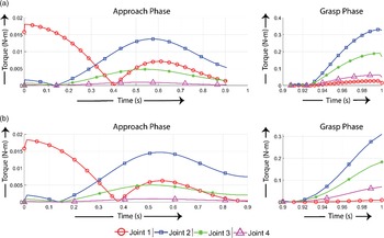
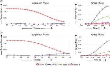
Figure 15 gives a comparison of the joint torque distribution of the thumb obtained from MSC.Adams
 $^{\circledR}$
(Fig. 15(a)) simulation with that of the optimal joint torque distribution (analytical) computed in MATLAB (Fig. 15(b)). The graphical plot during Approach phase shows the joint torque distribution before contact between the object and the thumb, while the plot during Grasp phase shows the joint torque distribution after contact has been established. It is observed that the maximum torque lies in the range 1.5 × 10⁻²
 $\sim$
2.0 × 10⁻² N-m during the Approach phase and within 0.3
 $\sim$
0.4 N-m during the Grasp phase in both the cases, that is, MSC.Adams
 $^{\circledR}$
and the Analytical solution computed in MATLAB. The maximum torque in the Approach phase for the MSC.Adams
 $^{\circledR}$
simulation before optimization is 1.81 × 10⁻² N-m for joint 1, 1.37 × 10⁻² N-m for joint 2, 4.8 × 10⁻³ N-m for joint 3, and 9.5 × 10⁻⁴ N-m for joint 4. The corresponding maximum joint torques in the Approach phase for the MATLAB simulation are 1.84 × 10⁻² N-m for joint 1, 1.47 × 10⁻² N-m for joint 2, 5 × 10⁻³ N-m for joint 3, and 9.6 × 10⁻⁴ N-m for joint 4. For the Grasp phase, the maximum joint torques in the MSC.Adams
 $^{\circledR}$
simulation are 2.7 × 10⁻² N-m for joint 1, 0.34 N-m for joint 2, 0.19 N-m for joint 3, and 6.2 × 10⁻² N-m for joint 4, while the torques required after optimization are 9.1 × 10⁻³ N-m for joint 1, 0.31 N-m for joint 2, 0.18 N-m for joint 3, and 6.95 × 10⁻² N-m for joint 4. As a consequence of optimization, the maximum joint torques required after contact are noticeably lower compared to the torques required prior to implementation of the optimization algorithm.
Torque distribution in various joints of the thumb, (a) Simulated data in MSC.Adams
 $^{\circledR}$
, (b) Analytical data using optimization algorithm.

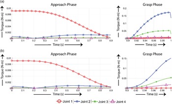
Similarly, a comparative study of the joint torque distribution of the index finger obtained from MSC.Adams
 $^{\circledR}$
and analytical solution in MATLAB are also investigated as shown in Figs. 16(a) and 16(b), respectively. The joint torque requirement of the index finger is below 1 × 10⁻² N-m for the Approach phase and increases to 0.15
 ${\sim}$
0.2 N-m for the Grasp phase. The maximum joint torques registered in the Approach phase is about 9.1 × 10⁻³ N-m for joint 1, 1.1 × 10⁻³ N-m for joint 2, 2.8 × 10⁻⁴ N-m for joint 3, and 3.8 × 10⁻⁵ N-m for joint 4 before optimization, while the maximum torques after optimization are 9.1 × 10⁻³ N-m for joint 1, 8.5 × 10⁻⁴ N-m for joint 2, 2 × 10⁻⁴ N-m for joint 3, and 2.95 × 10⁻⁵ N-m for joint 4. The maximum joint torques registered in the Grasp phase is 3.3 × 10⁻³ N-m for joint 1, 0.172 N-m for joint 2, 5.1 × 10⁻² N-m for joint 3, and 6.5 × 10⁻³ N-m for joint 4 in the MSC.Adams
 $^{\circledR}$
simulation (before optimization), while the values after optimization reduce down to 8.4 × 10⁻⁴ N-m for joint 1, 0.15 N-m for joint 2, 5.3 × 10⁻² N-m for joint 3, and 1.7 × 10⁻² N-m for joint 4 in the MATLAB simulation, after optimization. In comparison to that of the thumb, the joint torque requirements for the index finger are significantly reduced. First, this may be attributed to the lower mass of the finger, compared to the thumb (mass of the index finger is approximately 20 g based on the anthropometric values chosen in this study, while the mass of the thumb is close to double that, approximately 39 g). Second, it is due to the overall joint angle displacement of each finger, the net joint displacements of the thumb are larger than those of the joints of the index finger, as seen from Fig. 14. Due to these reasons, the torque requirements for the joints increase significantly.
Torque distribution in various joints of the index finger, (a) Simulated data in MSC.Adams
 $^{\circledR}$
, (b) Analytical data using optimization algorithm.

Finally, Figs. 17(a) and 17(b) shows the comparative results of the joint torque distribution for the motion of the middle finger both obtained from numerical simulation in MSC.Adams
 $^{\circledR}$
and analytical data using optimization. The joint torque requirement of the middle finger lies below 1.5 × 10⁻² N-m for the Approach phase and increases to 8 × 10⁻²
 $\sim$
0.1 N-m for the Grasp phase. The maximum joint torques computed in the Approach phase is about 1.23 × 10⁻² N-m for joint 1, 8.53 × 10⁻⁴ N-m for joint 2, 2.77 × 10⁻⁴ N-m for joint 3, and 4.65 × 10⁻⁵ N-m for joint 4 before optimization, while the maximum torques after optimization are 1.23 × 10⁻³ N-m for joint 1, 1.96 × 10⁻³ N-m for joint 2, 4.5 × 10⁻⁴ N-m for joint 3, and 6.86 × 10⁻⁵ N-m for joint 4. The maximum joint torques registered for the middle finger in the Grasp phase is 1.5 × 10⁻³ N-m for joint 1, 7.7 × 10⁻² N-m for joint 2, 3.18 × 10⁻² N-m for joint 3, and 7 × 10⁻³ N-m for joint 4 in the MSC.Adams
 $^{\circledR}$
simulation (before optimization) while the values after optimization change to 7.7 × 10⁻⁴ N-m for joint 1, 8.25 × 10⁻² N-m for joint 2, 2.36 × 10⁻² N-m for joint 3, and 7.18 × 10⁻³ N-m for joint 4 in the MATLAB simulation, after optimization. For all three fingers, joint 1 has the maximum torque load. This is mainly due to the fact that the gravitational axis points in the −ZW direction in the simulation. The torque generated by the weight of each phalange on joint 1 directly opposes the torque required to hold the fingers stable. In the Grasp phase, after the finger contacts the object, the torque required to counter the finger weight is instead provided by the friction force acting at the tip, thus reducing the load on the abduction/adduction joint and leaving the flexion/extension joints to deal with the contact stress generated.
Torque distribution in various joints of the middle finger, (a) Simulated data in MSC.Adams
 $^{\circledR}$
, (b) Analytical data using optimization algorithm.

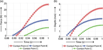
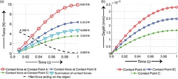
Both the normal contact force distribution at each point of contact between the finger and the object and the net force acting on the object due to the fingers are shown in Fig. 18(a). Here, the normal contact forces shown are calculated with respect to the reference frame placed at the point of contact, described in Fig. 6(b). At the start of the Grasp phase, the net force acting on the object is zero, corresponding to zero penetration depth. Now, as the penetration depth increases, the net force on the object increases accordingly and succeeds in nearly countering the other external forces acting on it. Figure 18(b) shows the penetration depth profiles between the fingers and object at each point of contact. Further, it is to be noted that in this study, only gravitational force has been considered as an external force. There is a residual force of
 $\sim$
0.089 N acting on the object at the end of the grasp, for a given set of contact forces and contact friction forces. The thumb provides the opposition motion, and hence exerts the maximum contact force of 9.873 N in order to counter the forces exerted by the other two fingers. Since the location of contact points is random, the contact forces exerted by the index and middle fingers are not uniform (6.35 N by the index and 4.7 N by the middle finger), as expected. The grip force exerted by the hand is in close range to the levels required for activities of daily living, as determined in a study for the evaluation of the prosthetic hand “Frederica” [Reference Esposito, Savino, Cosenza, Andreozzi, Gargiulo, Polley, Cesarelli, D’Addio and Bifulco57], though it is attributed to power grasp. Again, the maximum penetration achieved by the fingers after optimization is
 $\sim$
3.3 mm, which is less in comparison to the limiting conditions for the constraints given in Table V.
(a) Normal Contact force distribution , (b) penetration depth profiles for the optimized motion of the hand in the Grasp phase.

As mentioned above, the Grasp Energy required for executing the Grasp phase after optimization is about 55.9 mJ, while the Grasp Energy obtained from the simulation in MSC.Adams
 $^{\circledR}$
is 73.6 mJ. This reduction in the energy required to execute the Grasp phase proves the efficacy of the developed grasp optimization algorithm.
8. Conclusions and Scope for Future Work
The present study successfully demonstrates a novel grasp optimization algorithm, in which the information of grasp trajectory obtained from a remotely located user can be used to move a robotic gripper in an identical path. The optimization procedure minimizes the Grasp Energy-based objective function and determines an optimal distribution of contact forces subject to equality and inequality constraints. The optimization algorithm also introduces an instantaneous IK algorithm, which provides solutions for a robotic manipulator with multiple end-effectors, given that neither of the target task-space trajectories exceed its joint limits. A humanoid robotic hand model has been used to demonstrate the efficacy of the algorithm, and the results have been compared with CAD model simulated in MSC.Adams
 $^{\circledR}$
, keeping all the conditions similar.
The results obtained by executing the optimization algorithm reveals that the algorithm can obtain a desirable contact force configuration, to counteract known external forces acting on the object. Using the configuration, locally optimal cartesian trajectories can be selected for each finger, such that traversing them consumes the least net energy by the gripper, for a given set of contact points. This implies that, even though the energy consumed by any one finger may not be optimal, the net energy consumed by the entire gripper for securing the grasp is the minimum for that set of contact points. It is seen that utilizing the grasp optimization algorithm in analytical approach reduces the energy to grasp an object and is less compared to that computed in numerical approach using MSC.Adams
 $^{\circledR}$
solver. Again, due to arbitrary positioning of the hand, the contact force distribution that counteracts the gravitational force of the object is asymmetric, with the index finger and thumb carrying the majority of the load.
Further, in the present study, the described robotic humanoid hand is a theoretical model for the purposes of implementing the optimization algorithm. The comparison with the simulated data in MSC.Adams
 $^{\circledR}$
has paved a way for further design iterations with the proposed algorithm aiming at mechanical designs of the robotic hand with twenty DoFs along with the selection of suitable actuators for the same to achieve optimal motion of gripper fingers (each four DoFs). Future work will also focus on finger-tip and object interaction, taking into account surface area of contact instead of the simple point-to-point contact modeled in the present study. This will help in describing a more accurate behavior of the fingers upon contact. Further, the choice of impact acceleration (Grasp phase) for calculation of the Grasp Energy is limited to a constant value. The effect of time-dependent linear and nonlinear Grasp phase acceleration profiles needs to be explored.
In the present study, the computation is carried out offline, that is, the optimization algorithm is separately executed based on pre-determined operating conditions, and the results are implemented on the robot hand model. Future work in this study entails the development of active force control algorithms with more efficient solutions, based on advanced optimization methods that can be used online for real-time implementation in humanoid robotic hand for grasping of rigid objects, while allowing grasps with a larger number of contact points, such as in power grasps.
Acknowledgement
The authors are grateful to DRDO- J. C. Bose Center for Advance Technology, Kolkata, for supporting the research work.
Competing Interests Declaration
The author(s) declare none.
Appendix: Grasp Optimization Algorithm
The grasp optimization algorithm developed in the present study has been summarized as follows:
A.1 The Objective Function
Minimize,
 $$G{E_{net}} = \sum\limits_{j = 1}^N {\sum\limits_{i = 1}^{{L_j}} {\int\limits_{t = t1}^{tF} {(\rho + 1)} } } {\rm{ (}}\lambda \dot \delta + K){\delta ^\rho }dt,$$
subject to,
 \begin{align*}0 \le \delta \le {\delta _{max}},\end{align*}
 \begin{align*}0 \le \dot \delta \le {\dot \delta _I} \le {\dot \delta _{max}},\end{align*}
 $$ - {\rm{ |}}{{\ddot \delta }_{max}}| \le \ddot \delta {\rm{ < }}0,$$
 \begin{align*}0 \lt {t_{{I_{min}}}} \le {t_I} \le {t_{{I_{max}}}} \lt {t_F},\end{align*}
 $${\left\{ {\sum\limits_{j = 1}^N {\sum\limits_{i = 1}^{{L_j}} {{{\vec h}_{{e_{ji}}}}} } } \right\}_{t = {t_F}}} + {\vec F_e} = 0,$$
 \begin{align*} - f_{ji}^x + \frac{\mu }{{\sqrt 2 }}{F_{{n_{ji}}}} \lt 0,\end{align*}
 \begin{align*}f_{ji}^x + \frac{\mu }{{\sqrt 2 }}{F_{{n_{ji}}}} \lt 0,\end{align*}
 \begin{align*} - f_{ji}^y + \frac{\mu }{{\sqrt 2 }}{F_{_{ji}}} \lt 0,\end{align*}
 \begin{align*}f_{ji}^y + \frac{\mu }{{\sqrt 2 }}{F_{{n_{ji}}}} \lt 0.\end{align*}
A.2 Step-wise computation of the grasp optimization algorithm
Step 1: Selection of a time-based penetration acceleration profile, such that the impact acceleration lies within the range given in Eq. (13c), assuming
 ${\ddot \delta _{max}}$
is known. Here, the acceleration profile is arbitrarily chosen as a constant,
 ${a_1}$
, satisfying the constraints (
 ${a_1} \lt 0$
).
Step 2: Selection of the initial time of impact
 ${t_I}$
from the range given in Eq. (14), assuming
 ${t_{{I_{min}}}}$
,
 ${t_{{I_{max}}}}$
and
 ${t_F}$
are known.
Step 3: Integration of the penetration acceleration with respect to time, such that the penetration velocity profile is given by,
 \begin{align} \dot \delta = {a_1}t + {c_1} \end{align}
Using the boundary condition,
 $${\{ \dot \delta \} _{t = {t_F}}} = 0,\;$$
the instantaneous penetration velocity profile is given by,
 \begin{align} \dot \delta = {a_1}t - {a_1}{t_F} \end{align}
Step 4: Calculation of the Impact velocity, given by,
 $${\dot \delta _I} = {a_1}{\rm{(}}{t_I} - {t_F})$$
Step 5: Integration of the penetration velocity with respect to time, such that the penetration depth profile is given by,
 $$\delta = {{{a_1}{t^2}} \over 2} - ({a_1}{t_F})t + {c_2}.$$
Using the boundary condition,
 ${\{ \delta \} _{t = {t_I}}} = 0,$
the instantaneous penetration depth profile is calculated as,
 $$\delta = {{{a_1}{t^2}} \over 2} - ({a_1}{t_F})t + ({a_1}{t_F}{t_I} - {{{a_1}t_I^2} \over 2}).$$
Step 6: Determination of the value of
 ${\dot \delta _I}$
using Eq. (22) and check if the value is within the desired range given by Eq. (13b)).
Step 7: Evaluation of the Eq. (24b) at t = t
F
, if the condition in step 6 is satisfied, to calculate the net penetration depth for the selected
 ${a_1}$
and
 ${t_I}$
. Check if the value is within the range specified by Eq. (13a).
Step 8: Calculation of the normal force F n at t = t F , if the steps 6 and 7 are satisfied. Thus, substituting Eqs. (21b) and (24b) in Eq. (4):
 $${F_n} = \left( {\lambda {{\left( {{{{a_1}{t^2}} \over 2} - ({a_1}{t_F})t + \left( {{a_1}{t_F}{t_I} - {{{a_1}t_I^2} \over 2}} \right)} \right)}^\rho }} \right){\rm{(}}{a_1}t - {a_1}{t_F}) + K{\left( {{{{a_1}{t^2}} \over 2} - ({a_1}{t_F})t + \left( {{a_1}{t_F}{t_I} - {{{a_1}t_I^2} \over 2}} \right)} \right)^\rho }$$
Then, at t = t
F
, for the boundary condition,
 ${\{ \dot \delta \} _{t = {t_F}}} = 0$
, Eq. (25) reduces to,
 $${\{ {F_n}\} _{t = {t_F}}} = {K^*}{\left( {{{{a_1}} \over 2}{{({t_F} - {t_I})}^2}} \right)^\rho }$$
Step 9: Calculation of the friction forces f
x
and f
y
, using the value of
 ${F_n}$
obtained from Eq. (26) in step 8 by applying the bounds given in Eqs. (16a) – (16d). The friction forces in the local contact frame are calculated as:
 \begin{align} {f_x} = \frac{{{k_1}\mu }}{{\sqrt 2 }}{F_n} \end{align}
 \begin{align} {f_y} = \frac{{{k_2}\mu }}{{\sqrt 2 }}{F_n} \end{align}
where k 1 , k 2 ε (0,1).
Step 10: Satisfying the equilibrium condition for a multiple sets of friction forces, by varying the values of k 1 and k 2 using Eqs. (27a) and (27b). The force vector at a given point of contact turns out as:
 $${\vec h_e} = \left( {{{{k_1}\mu } \over {\sqrt 2 }}{F_n},\;\;{{{k_2}\mu } \over {\sqrt 2 }}{F_n},\;\;{F_n}} \right){\;^T}$$
Step 11: Satisfying of the equilibrium constraint in Eq. (15) after computation of Eq. (28) for each contact point.
Step 12: Evaluation of the objective function, given by Eq. (12), if all the above-mentioned constraints are successfully satisfied for a given set of penetration acceleration coefficients and time of impact.
Step 13: Computation of the minimal value or the optimum value of Grasp-Energy, after successful evaluation of the steps 1 – 12, for each set of contact frictions, penetration acceleration and impact time values.
Step 14: Determination of the set of optimal parameters corresponding to step 13.
Step 15: Selection of the joint trajectories requiring minimum joint torque.
-
Firstly, the Grasp phase inverse kinematics is performed for each Contact phase configuration solution, utilizing the optimal parameters determined in the previous steps. The procedures described in Section 6.1, by Eqs. (17a), (17b) and (18) are followed.
-
Secondly, after determining the joint torque profiles for each trajectory solution, the Approach phase joint trajectories are generated using the procedures given in Section 6.2.
-
Finally, the torque profiles for the possible Approach phase trajectories are determined.
Each corresponding solution of joint trajectories and torque profiles for both phases are concatenated. The complete joint torque profile, with the minimum infinity norm is selected, and the corresponding joint trajectory solution set is assigned as the optimal grasp trajectory.