Introduction
Nickel-based superalloys constitute an important class within the broader family of superalloys, with Ni as the main alloying element. They possess a combination of outstanding mechanical and physical properties in the temperature range of 540°C–1000°C, notably tensile and creep strength as well as resistance to thermal fatigue and oxidation, making them especially suitable for gas-turbine and jet-engine components. Reference Donachie and Donachie1 Alloying elements are selectively included to improve their performance. For instance, Ti, Al, and Nb contribute to the formation of precipitation strengthening phases (Ni3Al (γ′) and Ni3Nb [γ′′]), which are formed as coherent fine precipitates following aging. Other elements (e.g., Ta, Ti, Mo, Hf, W, Cr) contribute to the formation of carbides, which assist in grain-size control and resistance to grain-boundary sliding at high temperatures. Other elements (e.g., Al, Cr, La, Y, Ce) are added to improve their oxidation and corrosion resistance, which is essential to the aforementioned applications. Reference Donachie and Donachie1,Reference Durand-Charre2
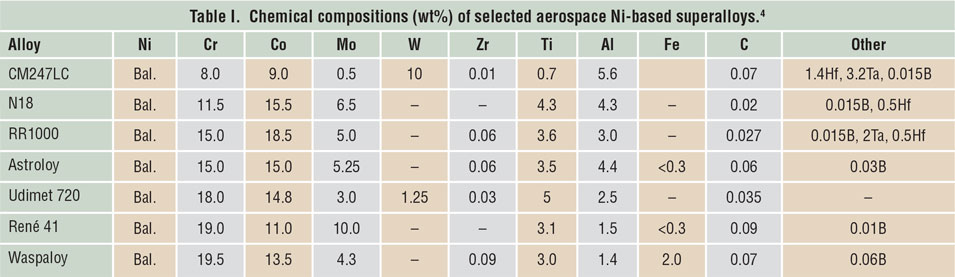
Generally, Inconel 718 (also called Alloy 718) has been the workhorse of the aero-engine sector, due to its combination of good weldability, forgeability, and strength up to 650°C at a reasonable cost. Reference Schafrik and Sprague3 There has been increasing interest in the development of Ni-based superalloys that are capable of higher-temperature performance, in order to increase the turbine entry temperature (TET) of gas turbines (the temperature of combustion byproduct gases entering the turbine section), which manifests in improved thermodynamic efficiency. Reference Reed4 As a result, newer alloys were developed to achieve this, including CM247LC, RR1000, René 41, Hastelloy-X, Waspaloy, Udimet 720, N18, and Astroloy ( Table I ). Reference Reed4
Chemical compositions (wt%) of selected aerospace Ni-based superalloys. Reference Reed4

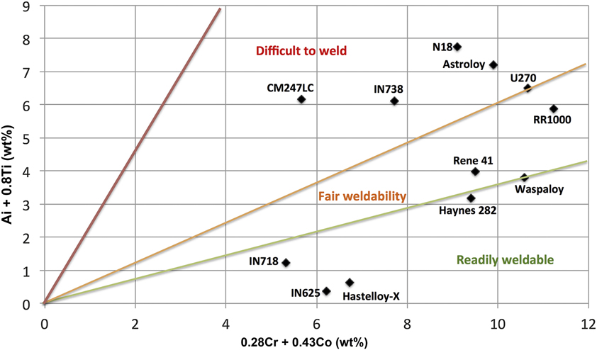
Despite their outstanding high-temperature performance, these alloys have limited weldability due to the presence of a high γ′-fraction (directly linked to the Ti + Al content), which increases the susceptibility of the alloys to cracking during postweld heat treatment (or reheating operations), also known as “strain-age cracking.” Reference Henderson, Arrell, Larsson, Heobel and Marchant5 The alloys also become susceptible to ductility-dip cracking (DDC), which is defined as the drop in ductility at intermediate temperatures (0.4–0.7× the melting point), and is typically associated with the formation of grain-boundary carbides in Ni superalloys. Reference Young, Capobianco, Penik, Morris and McGee6 This relationship between alloy chemistry and weld susceptibility is shown in Figure 1 . Reference Ott, Groh, Sizek and Loria7 This does not include other cracking mechanisms such as liquation and solidification cracking, which could occur during welding of alloys, regardless of the chemistry.
Weldability assessment diagrams for nickel-based superalloys using the chemical composition (wt%) of the γ′-forming elements (Al and Ti) and the carbide-forming elements (Cr and Co). Adapted with permission from Reference Reference Ott, Groh, Sizek and Loria7. © 2006 The Minerals, Metals and Materials Society.

In simple terms, additive manufacturing (AM) can be described as a multilayer/repeated welding process (see the introductory article in this issue). As such, AM is susceptible to the formation of weld-cracking defects. The processes are associated with rapid cooling rates that were reported to be as high as 106 K/s. Reference Harrison, Todd and Mumtaz8 This results in the formation of significant residual stresses as well as an epitaxially grown microstructure, with both resulting in structural integrity issues and anisotropy in mechanical properties. Process optimization for AM techniques, regardless of the type (e.g., selective laser melting [SLM], electron-beam selective melting, or direct energy deposition [DED] methods) has thus far been performed from an engineering perspective, due to a lack of fundamental understanding of the thermal impact of the process on the microstructure. This article aims to overview the outstanding issues in Ni superalloy AM, highlighting key challenges and current approaches for their mitigation, as well as the potential of AM for “tailoring” the material microstructure.
Residual stress
Residual stress is defined as stationary stress at equilibrium within a material. Reference Withers and Bhadeshia9,Reference Mercelis and Kruth10 It could arise from mismatches between components, areas within a body, or phases. Reference Withers and Bhadeshia9,Reference Withers and Bhadeshia11 Multiscale residual stresses are determined by their characteristic length: Type I macro-stresses vary over the dimensions of the component; Type II micro-stresses span grain dimensions; Type III form at the atomic scale. Reference Withers and Bhadeshia9,Reference Withers and Bhadeshia11,Reference Pinkerton, Shackleton, Moat, Li, Withers, Preuss, Allen, Hilton and Folwell12 Residual stress introduced by AM during the layer-by-layer processing is known to be complex and large. Reference Pinkerton, Shackleton, Moat, Li, Withers, Preuss, Allen, Hilton and Folwell12,Reference Gu, Meiners, Wissenbach and Poprawe13 It is attributed to the large spatiotemporal thermal gradients from localized rapid heating and fast cooling during processing. Reference Vrancken, Wauthlé, Kruth and Van Humbeeck14 In general, the presence of residual stress within AM parts (mainly arising close to the surface) is undesirable, especially tensile residual stress, as it reduces the effective fatigue and tensile properties and may distort the final geometry Reference Pinkerton, Shackleton, Moat, Li, Withers, Preuss, Allen, Hilton and Folwell12,Reference Vrancken, Wauthlé, Kruth and Van Humbeeck14,Reference Moat, Pinkerton, Li, Withers and Preuss15 and induce cracks. Reference Pinkerton, Shackleton, Moat, Li, Withers, Preuss, Allen, Hilton and Folwell12,Reference Gu, Meiners, Wissenbach and Poprawe13,Reference Zhong, Sun, Liu, Zhu and He16 When the residual stress overcomes the yield strength of the material, it causes distortion. A large amount of effort has been invested in the control and reduction of residual stresses in AM. Reference Parimi, Attallah, Gebelin, Reed, Huron, Reed, Hardy, Mills, Montero, Portella and Telesman17–Reference Prabhakar, Sames, Dehoff and Babu19
Experimental measurement of residual stress has been carried out by the hole drilling method, Reference Casavola, Campanelli and Pappalettere20,Reference Griffith, Schlienger, Harwell, Oliver, Baldwin, Ensz, Essien, Brooks, Robino and Smugeresky21 deflection method, Reference Vrancken, Wauthlé, Kruth and Van Humbeeck14,Reference Neugebauer, Keller, Hongxiao, Kober and Ploshikhin22 x-ray diffraction method, Reference Pinkerton, Shackleton, Moat, Li, Withers, Preuss, Allen, Hilton and Folwell12,Reference Vrancken, Wauthlé, Kruth and Van Humbeeck14 contour method, Reference Moat, Pinkerton, Li, Withers and Preuss15,Reference Rangaswamy, Griffith, Prime, Holden, Rogge, Edwards and Sebring23 and neutron diffraction. Reference Moat, Pinkerton, Li, Withers and Preuss15,Reference Rangaswamy, Griffith, Prime, Holden, Rogge, Edwards and Sebring23 Numerical simulations have also been developed based on finite element methods (FEM) to understand residual stress development, linking the AM process parameters to the melt pool and temperature gradient on the microscopic scale in order to suggest approaches for the reduction of the residual stress. Reference Neugebauer, Keller, Hongxiao, Kober and Ploshikhin22,Reference Vasinonta, Beuth and Griffith24–Reference Beuth and Klingbeil26 On the mesoscopic scale, studies were performed to assess the impact of the thermal field on residual stress development in individual laser paths and build layers. Reference Klingbeil, Beuth, Chin and Amon18,Reference Neugebauer, Keller, Hongxiao, Kober and Ploshikhin22,Reference Dai and Shaw27,Reference Wang, Felicelli and Pratt28 On the macroscopic scale, investigations have been performed to predict the deformation and macrostress. Reference Mercelis and Kruth10,Reference Vrancken, Wauthlé, Kruth and Van Humbeeck14,Reference Parimi, Attallah, Gebelin, Reed, Huron, Reed, Hardy, Mills, Montero, Portella and Telesman17,Reference Prabhakar, Sames, Dehoff and Babu19,Reference Neugebauer, Keller, Hongxiao, Kober and Ploshikhin22
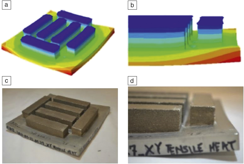
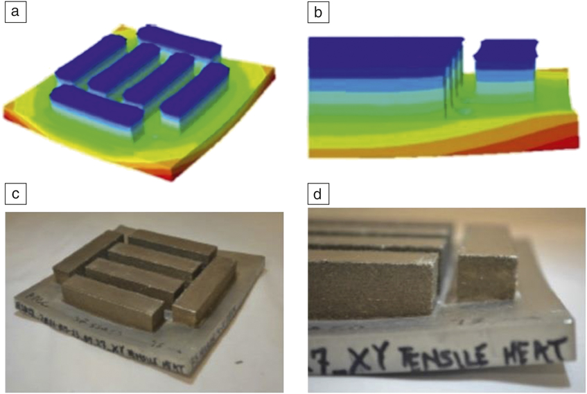
In general, the study of residual stress has been limited to simple geometries, such as thin walls for both AM manufactured samples and models, Reference Vrancken, Wauthlé, Kruth and Van Humbeeck14,Reference Vasinonta, Beuth and Griffith24,Reference Beuth and Klingbeil26 due to the high computational costs of using a fully coupled thermomechanical model in large-scale structures. The model results are in good agreement with the experimental measurements. Reference Prabhakar, Sames, Dehoff and Babu19,Reference Labudovic, Hu and Kovacevic29,Reference Zaeh and Branner30 Longitudinal residual stress, with tensile nature with a parabolic distribution, is found near the top of the samples and tends to increase with the number of deposited layers due to the decreasing thermal gradient. Reference Mercelis and Kruth10,Reference Griffith, Schlienger, Harwell, Oliver, Baldwin, Ensz, Essien, Brooks, Robino and Smugeresky21,Reference Labudovic, Hu and Kovacevic29,Reference Moat, Pinkerton, Hughes, Li, Withers and Preuss31–Reference D’Oliveira, da Silva and Vilar33 Stresses have also been shown to vary with increasing final build height in thin wall structures, based on the height of the measurement points and the scanning pattern, as longitudinal stresses change from tensile to compressive and may convert to tensile again toward the bottom. Reference Zaeh and Branner30,Reference Zekovic, Dwivedi and Kovacevic34 For the normal direction (building direction), residual stress is compressive in the center of the wall and gradually reverses to tensile toward the edges due to constraints on the baseplate from bending deformation, as shown in Figure 2 . Reference Pinkerton, Shackleton, Moat, Li, Withers, Preuss, Allen, Hilton and Folwell12,Reference Moat, Pinkerton, Li, Withers and Preuss15,Reference Prabhakar, Sames, Dehoff and Babu19,Reference Rangaswamy, Griffith, Prime, Holden, Rogge, Edwards and Sebring23,Reference Shamsaei, Yadollahi, Bian and Thompson35 Further modeling has revealed that the presence of high tensile stress near the edge is due to the baseplate constraining the thin wall from bending rather than an increase in the melt pool size. Reference Aggarangsi, Beuth and Griffith25
Comparison of warping during electron-beam melting of IN718 in (a–b) simulation results and (c–d) actual components, respectively, showing good agreement. Reprinted with permission from Reference Reference Prabhakar, Sames, Dehoff and Babu19. © 2015 Springer.
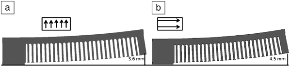
Theoretical and experimental studies have revealed that both the magnitude and trend of residual stress in AM components are governed by material properties (i.e., small coefficient of thermal expansion, large thermal diffusivity, high thermal conductivity), Reference Vrancken, Wauthlé, Kruth and Van Humbeeck14,Reference Dai and Shaw27,Reference Shamsaei, Yadollahi, Bian and Thompson35,Reference Gåård, Krakhmalev and Bergström36 phase transformation or precipitation, Reference Pinkerton, Shackleton, Moat, Li, Withers, Preuss, Allen, Hilton and Folwell12,Reference Rangaswamy, Griffith, Prime, Holden, Rogge, Edwards and Sebring23 geometry of components, Reference Casavola, Campanelli and Pappalettere20,Reference Aggarangsi, Beuth and Griffith25,Reference Beuth and Klingbeil26,Reference Zekovic, Dwivedi and Kovacevic34 the position of specimens, Reference Casavola, Campanelli and Pappalettere20 processing parameters, Reference Pinkerton, Shackleton, Moat, Li, Withers, Preuss, Allen, Hilton and Folwell12,Reference Moat, Pinkerton, Li, Withers and Preuss15,Reference Beuth and Klingbeil26,Reference Wang, Felicelli and Pratt28 baseplate, Reference Mercelis and Kruth10,Reference Prabhakar, Sames, Dehoff and Babu19 and scanning pattern. Reference Mercelis and Kruth10,Reference Klingbeil, Beuth, Chin and Amon18,Reference Neugebauer, Keller, Hongxiao, Kober and Ploshikhin22,Reference Rangaswamy, Griffith, Prime, Holden, Rogge, Edwards and Sebring23,Reference Dai and Shaw27,Reference Zekovic, Dwivedi and Kovacevic34,Reference Nickel, Barnett and Prinz37 It was found that substrate preheating and insulation could help reduce residual stresses by limiting the thermal gradient between layers and controlling the melt pool, but it may change stress from tension to compression. Reference Klingbeil, Beuth, Chin and Amon18,Reference Casavola, Campanelli and Pappalettere20,Reference Vasinonta, Beuth and Griffith24,Reference Beuth and Klingbeil26,Reference Labudovic, Hu and Kovacevic29,Reference Finnie, Cheng, Finnie, Drezet and Gremaud38,Reference Kupkovits and Neu39 Shorter laser scanning paths and larger layer thickness lead to less stress due to reduction in the temperature gradient, as shown in Figure 3 . Reference Mercelis and Kruth10,Reference Gu, Meiners, Wissenbach and Poprawe13,Reference Parimi, Attallah, Gebelin, Reed, Huron, Reed, Hardy, Mills, Montero, Portella and Telesman17,Reference Neugebauer, Keller, Hongxiao, Kober and Ploshikhin22,Reference Rangaswamy, Griffith, Prime, Holden, Rogge, Edwards and Sebring23,Reference Zaeh and Branner30,Reference Nickel, Barnett and Prinz37 Alternating the scanning direction also helps lower stresses. Reference Dai and Shaw27,Reference Zaeh and Branner30
Numerical simulation illustrating varying degrees of deflection in components fabricated using (a) short scanning vector and (b) long scanning vector, showing the influence of the scan strategy on distortion in selective laser melting. Reference Neugebauer, Keller, Hongxiao, Kober and Ploshikhin22

In summary, it is difficult to create Ni-based superalloy AM structures with reduced residual stresses (that could be effectively mitigated using postprocess thermal treatments), due to the insufficient flexibility of the AM platforms and the computational cost of predicting scanning strategies and process parameters that will minimize residual stresses. Future AM platforms should employ physics-inspired scanning strategies that will aim to reduce thermal stresses by controlling the thermal gradients in complicated 3D structures. In addition, the hot powder bed systems used in current electron-beam-based platforms should be extended to laser-based systems to mitigate residual stresses in situ, similar to electron-beam selective melting systems. Finally, computationally nonintensive codes need to be developed to predict the thermal fields and residual stresses, and potentially control residual stress development on the fly, if these codes can be employed on AM platforms.
Defect formation in AM of Ni-based superalloys: Porosity and cracking
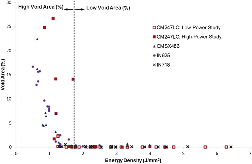
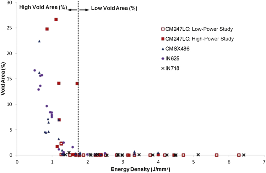
There are two defects commonly associated with AM of Ni-based superalloys—porosity and cracking—and multiple morphologies of these can be identified. The prevalence of defect type is influenced by the AM technique used, the process variables implemented within each technique, and by the composition and morphology of the parent material. Porosity formation in the AM of Ni-based superalloys is predominantly process-induced and does not appear to differ significantly between alloy compositions. Reference Carter, Wang, Read, Khan, Aristizabal, Essa and Attallah40 It should, however, be noted that residual porosity in the feedstock material (powder) can significantly differ depending on its production route (e.g., gas atomization versus plasma rotating electrode powders), and this porosity can be passed on to the built part. Reference Qi, Azer and Ritter41 Generally, insufficient melting resulting from low-energy input or poor powder spreading can lead to the formation of large internal voids, Reference Carter, Essa and Attallah42,Reference Ramsperger, Singer and Körner43 following a reducing trend in porosity with increase in energy density per unit area. Interestingly, the threshold for consolidation appears to be less dependent on the Ni superalloy type, as seen in Figure 4 , which shows the transition from lack of fusion to consolidation for several Ni-based superalloys. A similar threshold for consolidation has been seen in direct laser deposition (DLD)-processed Hastelloy-X. In DLD, powders are sprayed from a nozzle and melted in situ using a laser. Reference Wang, Wu and Clark44
Void area (%) plotted against energy density generated from collated results of five different studies relating to selective laser melting of Ni superalloys IN718, IN625, CM247LC, and CMSX486. Reference Carter, Wang, Read, Khan, Aristizabal, Essa and Attallah40
Another potential cause for defect formation is balling, which occurs when a track of deposited material has reduced wettability due to an increase in surface tension; a propensity to minimize the surface energy leads to the formation of balls of material, resulting in a rough surface finish and surface porosity. In SLM and DLD of Ni-based superalloys, balling tends to form when low-input energies are used; this can result from an increase in scanning speed Reference Jia and Gu45 or a decrease in laser energy. Reference Mumtaz, Erasenthiran and Hopkinson46 In addition, the formation of oxides owing to insufficient inert gas shielding can also increase surface tension. Reference Das, Fuesting, Danyo, Brown, Beaman and Bourell47 However, pores can start to form once the energy density reaches a high enough level to trigger the keyhole-welding mode, where the material exposed to the heat source starts to evaporate, forming a deep keyhole.
Keyhole-induced porosity has been reported to occur in varying geometries according to the spatial level at which it occurs in the keyhole (e.g., the root, middle, or top). While there is some debate as to which morphology comes from where, it is generally agreed that porosity is the result of metal vapor rising out of the keyhole and becoming trapped during keyhole collapse. Reference Wei, Kou and Cheng48 Keyhole porosity is quite common in Ni-based superalloys due to the large melting range created by having numerous alloying elements. Keyhole porosity has been reported to increase with increasing energy density. Reference Wang, Wu and Clark44,Reference Cloots, Uggowitzer and Wegener49 The heat source (laser or electron beam) profile has been shown to influence keyhole formation, with a broadening of the beam leading to a reduction in keyholing. Reference Cloots, Uggowitzer and Wegener49,Reference Helmer, Körner and Singer50
Four cracking mechanisms can be identified resulting from the AM processing of Ni-based superalloys, including solidification cracking, liquation cracking, DDC, and postweld heat treatment (PWHT) cracking. Reference Carter, Attallah, Reed, Huron, Reed, Hardy, Mills, Montero, Portella and Telesman51 Rapid cooling during solidification results in the trapping of liquid between already solidified dendrites; when stressed, these weak mushy regions rupture and tear, Reference Carter, Attallah, Reed, Huron, Reed, Hardy, Mills, Montero, Portella and Telesman51,Reference Cross, Böllinghaus and Herold52 creating jagged solidification cracks. Solidification cracking has been seen to occur when high energy densities are implemented during AM. Reference Carter, Attallah, Reed, Huron, Reed, Hardy, Mills, Montero, Portella and Telesman51,Reference Dye, Hunziker and Reed53,Reference Rush, Colegrove, Zhang and Broad54 Conversely, other work has emerged suggesting that high energy densities actually lead to a reduction in cracking. Reference Ramsperger, Singer and Körner43,Reference Jia and Gu45 In addition to this, component size has also been shown to affect the onset of solidification cracking, with larger components producing greater thermal gradients and increased solidification cracking. Reference Dye, Hunziker and Reed53 Several studies have recently emerged on the effects of Zr segregation on solidification cracking in IN738LC. It is suggested that Zr films become trapped between dendrite arms near the grain boundaries, embrittling the grain-boundary region; when stressed, cracks form with similar morphology to solidification cracking. Reference Cloots, Uggowitzer and Wegener49,Reference Tsai, Wang, Bor and Hsu55,Reference Heydari, Fard, Bakhshi and Drezet56
Other studies point to the impact of the scanning strategy on the formation of solid-state DDC, indicating the role of re-melting and rapid solidification with increasing fraction of high-angle grain boundaries and grain-boundary phases, which leads to the development of DDC when combined with high residual stresses. Reference Carter, Martin, Withers and Attallah57 The welding literature suggests that DDC occurs due to the formation of carbides at grain boundaries, Reference Young, Capobianco, Penik, Morris and McGee58 with some reports also suggesting grain-boundary shearing. Reference Collins and Lippold59–Reference Collins, Ramirez and Lippold61 It should be noted that in the latter case, DDC in Ni superalloys always forms along regions of high-angle grain boundaries. Reference Lippold62 Low-melting-point phases resulting from constitutional undercooling form in grain-boundary regions; when heat is applied, these phases melt and the liquid penetrates the grain boundaries, weakening them and resulting in liquation cracking. Tensile stresses created by contracting material elsewhere pull apart the weakened grain boundaries, forming relatively smooth cracks. Reference Carter, Attallah, Reed, Huron, Reed, Hardy, Mills, Montero, Portella and Telesman51 Nonetheless, limited studies identified high-energy input during AM as the reason for liquation cracking. Reference Bi and Gasser63
Microstructural anisotropy
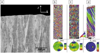
AM techniques generally result in a columnar grain structure, with grains extending over several re-melt layers. The rapid solidification, combined with the directionality in heat losses vertically toward the substrate, results in epitaxial growth in either the powder bed or the DED methods, Reference Das64,Reference Parimi, Ravi, Clark and Attallah65 see Figure 5 . Some variability was observed in SLM fabricated structures, whereby the use of a chessboard scanning strategy (in which the laser moves randomly between square islands to evenly distribute the heating) resulted in the formation of nearly equiaxed grains regions embedded within primarily columnar grain regions. Reference Carter, Martin, Withers and Attallah57 A similar variation was also observed in DLD methods, and was attributed to the cooling history of the builds, which can also be manipulated using the build strategy. Reference Liu, Lin, Yang, Song, Chen and Huang66 More importantly, due to the repeated heating nature of the process, the microstructure also shows inhomogeneity on the tens of microns scale, which manifests itself in the “fish-scale” morphology seen in Figure 5a Reference Vilaro, Colin, Bartout, Naze and Sennour67 and the inhomogeneity in grain structure or segregation. Reference Amato, Gaytan, Murr, Martinez, Shindo, Hernandez, Collins and Medina68
(a) Coarse columnar grains extending several layers along the build direction in selective laser melting-processed Nimonic 263, also showing the fish-scale morphology, Reference Vilaro, Colin, Bartout, Naze and Sennour67 and (b–d) electron backscatter diffraction maps for direct laser deposition-processed IN718, showing the impact of the deposition strategy on the grain morphology and texture; (b) unidirectional deposition, (c) bidirectional deposition, and (d) high laser power. Reference Parimi, Ravi, Clark and Attallah65

The anisotropy in the grain structure is not an issue itself, provided that it can be utilized to tailor a specific mechanical performance similar to the directionality of directionally cast (DS) structures. Nonetheless, this potential has not been fully exploited by the AM user community. Recent work has shown the potential of AM in controlling both the grain size and crystallographic orientation by manipulating the process parameters (Figure 5b–d).
The other challenge associated with the microstructure is the metastable nature of the rapid solidification byproducts in the build. Most Ni-based superalloy AM builds show either considerable levels of interdendritic segregation or other undesirable solidification-induced phases (e.g., Laves phase). Reference Parimi, Ravi, Clark and Attallah65 As a result, there is always a need for a postprocessing treatment, such as hot isostatic pressing (HIP) to heal the defects caused by the AM processes, often in addition to a solution and aging heat treatment to create the optimum size and fraction of precipitates for high-temperature properties. These postprocessing operations obviously add to the cost of AM processes, making them less attractive.
Mechanical properties
One of the challenges affecting the maturity of AM for Ni superalloys is the lack of sufficient information in the public domain on their high-temperature mechanical performance, notably their creep and high-temperature fatigue performance, due to the testing costs. Furthermore, the available data were generated through various AM platforms, feedstock material characteristics and chemistries, process parameters, scanning strategies, build/sample geometry, and postprocessing treatments, making it difficult to obtain a coherent consensus about the mechanical performance of AM structures.
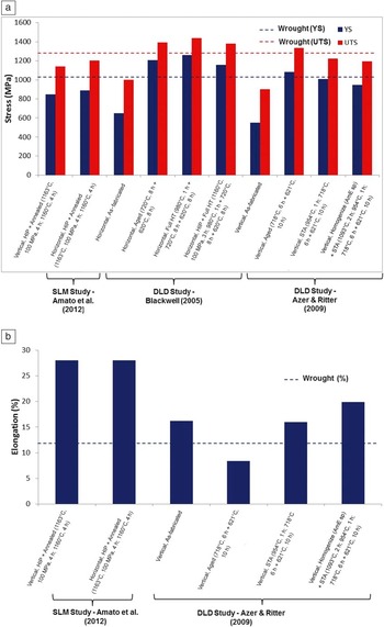
Figure 6 Reference Blackwell69 shows the tensile properties of SLM- and DLD-processed IN718, collated from a number of studies. One clear observation is that the as-fabricated properties do not achieve the required performance. Nonetheless, postprocessing, whether or not employing HIP, shows a significant improvement in the tensile properties, especially when a full solution treatment and aging sequence is utilized. Although earlier studies showed strength levels in SLM-processed structures lower than those in wrought material, a recent study Reference Chlebus, Gruber, Kuźnicka, Kurzac and Kurzynowski70 showed that strength levels exceeding the wrought condition can be achieved in SLM-processed IN718 once the postprocessing heat treatment is optimized. Nonetheless, heat treatments cannot address the intrinsic anisotropy in the mechanical properties, which usually results in the horizontally built samples slightly over-performing the vertically built samples.
Collated tensile properties of selective laser melting (SLM) and direct laser deposition (DLD)-processed IN718 from a number of studies compared to wrought IN718 (AMS5662), showing (a) ultimate tensile strength (UTS) and yield strength (YS) and (b) tensile elongation. Post-fabrication treatments include hot isostatic pressing (HIP), full heat treatment (full HT), and solution treatment and aging (STA). Reference Qi, Azer and Ritter41,Reference Amato, Gaytan, Murr, Martinez, Shindo, Hernandez, Collins and Medina68,Reference Blackwell69

Conclusions
During the last decade, research on AM of Ni superalloys has addressed a number of material and process challenges. Further work is still required to address the residual stress development, microstructure–properties development, and process optimization. This depends on the improvement of flexibility in the AM platforms as well as the development of rapid computational techniques that can simulate the process to maximize the process and product performance.