I. INTRODUCTION
Advances in thermoelectric (TE) materials are essential for the development of the next generation of energy conversion devices. Devices in the future may provide localized cooling or efficiently convert waste heat into electricity. The conversion efficiency of TE materials is dependent on high Seebeck coefficient and electrical conductivity and low thermal conductivity, which are combined to define the figure of merit, ZT, as

where S, ρ, and κ are the Seebeck coefficient, electrical resistivity, and thermal conductivity, respectively.Reference Tritt and Subramanian1 The power factor (PF) represents a key portion of the figure of merit and can more easily give a strong indication of the quality of TE materials as it is just the product of the Seebeck coefficient squared with the electrical conductivity, σ, as in Eq. (2):

with

where μ, q, and n are the mobility, charge of the carrier, and carrier concentration, respectively.Reference Van Zeghbroeck2 Additionally, the Seebeck coefficient of a semiconductor is

where ce ,κ B, q, and ε F are the specific heat, Boltzmann constant, charge of the carrier, and the Fermi energy, respectively.Reference Xu, Funahashi, Shikano, Matsubara and Zhou3 Obviously, it is desired to make the figure of merit as large as possible. Currently, devices with a figure of merit greater than 1 represent the best of those materials in practical use. Examples of the best available materials are CsBi4Te6, Bi2Te3, and PbTe, which all have the figure of merit near 1 in their optimum temperature regimes of 200 K, 400 K, and 600 K, respectively.Reference Tritt and Subramanian1 In the quest for new materials for TE, one desires a material with high electrical and small thermal conductivity to maximize the figure of merit. This requirement benefits from a decoupling between the phonons and electrons, accomplished by using crystals containing heavy elements, multiple interfaces, and large unit cells. Many heavy metal materials such as those referenced above are toxic, and others have low melting points, making them useless at high temperatures. Metal oxides have attracted much attention because of their thermal stability and high operational temperatures. In addition, metal oxides are made up of lighter, more common elements that form complex structures made of large unit cells associated with low thermal conductivity.Reference Snyder and Toberer4 Superlattices demonstrate better performance by creating many layers of periodic interfaces, which help to scatter phonons, reducing the thermal conductivity.Reference Bottner, Chen and Venkatasubramanian5 Ca3Co4O9 is a natural superlattice consisting of two overlapping lattices CoO2 and Ca2CoO3.Reference Koumoto, Terasaki and Funahashi6, Reference Tyson, Chen, Jie, Li and Tu7 The maximum operational temperature for Ca3Co4O9 is over 1000 K, making it a strong candidate for high-temperature applications.
High-quality polycrystalline TE thin films can have low ρ and high Seebeck coefficients.Reference Venkatasubramanian, Slivola, Colpitts and O’Quinn8 Growing in a thin film form allows the material to be deposited directly onto a substrate in a specific location and patterned if necessary. Thin films of clathrates, for example, have recently been grown using a pulsed laser deposition process.Reference Hyde, Beekman, Nolas, Mukherjee and Witanachchi9 It is well known that increased boundaries can lower thermal conductivity.Reference Bertini, Billquist, Christensen, Gatti, Holmgren, Iverson, Mueller, Muhammed, Noriega, Palmqvist, Platzek, Rowe, Saramat, Stiewe, Toprak, Williams and Zhang10–Reference Toprak, Stiewe, Platzek, Williams, Bertini, Muller, Gatti, Zhang, Rowe and Muhammed12 Both thin films and nanoparticles increase the number of interfaces, which helps lower thermal conductivity and also causes a slightly higher resistivity. This implies that optimizing these effects could result in maximizing the figure of merit, ZT. Nanoparticles have been shown to have a significant effect on the performance of materials such as bismuth telluride. The incorporation of bismuth telluride nanostructures into bulk bismuth telluride ingots to form composites resulted in substantial improvement of the figure of merit, ZT, on the order of 40%, finally shattering the ceiling for bulk material in which the figure of merit was on the order of 1.Reference Poudel, Hao, Ma, Lan, Minnich, Yu, Yan, Wang, Muto, Vashaee, Chen, Liu, Dresselhaus, Chen and Ren13 Recent models of transport properties suggest that PF can be related to an optimized size of the grains.Reference Popescu, Woods, Martin and Nolas14–Reference Zebarjadi, Esfarjani, Shakouri, Bahk, Bian, Zeng, Bowers, Lu, Zide and Gossard16 Others have grown Ca3Co4O9 nanoparticles by several methods, including sol–gel, electrospinning, and in some cases enhanced their results with spark plasma sintering (SPS).Reference Wang, Sui, Cheng, Wang and Su17–Reference Zhang, Zhang, Lu and Zhang21
In this study, the properties of Ca3Co4O9 films produced by microwave plasma–assisted spray (MPAS) are measured as a function of the initial concentration of the precursor. The resistivity, Seebeck coefficient, and therefore the PF of a set of films grown by MPAS with varying concentrations of calcium and cobalt salts were determined.
Spray deposition processes have been used as an approach to grow films with nanoparticulate features. Initially, spray pyrolysis studies were carried out using a laser to intercept a directed spray and heat the droplets, in a process called laser-assisted spray pyrolysis (LASP). First, molar solutions were prepared by dissolving stoichiometric amounts of chlorides—CaCl2 and CoCl2—in deionized H2O. This precursor solution was transferred into a small cylinder containing an ultrasonic nebulizer. The nebulizer was operated at a frequency of 2.4 MHz to generate uniformly distributed droplets with an average diameter of 1.5 μm.Reference Mitzutani, Uga and Nishimoto22 The aerosol was injected into the flow tube by a carrier gas through a nozzle. The chamber was kept at a constant pressure to maintain a constant spray. A typical spray pyrolysis process consists of two steps. The first is the deposition of the elements of interest onto the substrate and the evaporation of the solvent. Then, a second step may be necessary to anneal the material to make it crystalline. The LASP approach, when combined with annealing, yielded crystalline films but with high resistivity and large agglomeration.Reference Wangensteen, Witanachchi and Mukherjee23
We have developed an MPAS deposition technique and used it to grow nanograined films of Ca3Co4O9. In MPAS, the microwave was used to heat the spray droplets in flight. Heating causes the evaporation of the solvent, condensing the inorganic salts into a smaller particle. Because a high-temperature zone exists within the width of the waveguide, and also an additional decreasing temperature gradient on moving toward the substrate, the particles will be partially or completely reacted before deposition on the substrate. Compared to the laser technique, the microwave process results in the advantages of a larger interaction area and higher power, and thus more thermal energy for the spray droplet to interact with.
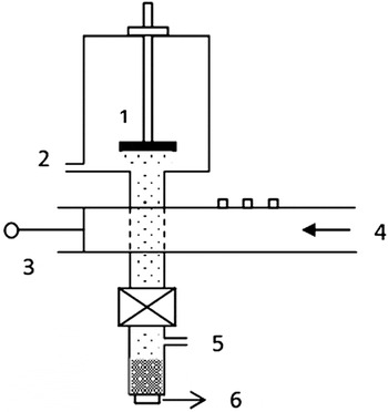
In this MPAS process, radiation transferred through a waveguide was coupled into a flowing gas in a quartz tube to create a plasma. This was done by using tuning pegs and an adjustable slide as shown in Fig. 1. A more detailed drawing and explanation was provided in earlier work.Reference Merlak24, Reference Wangensteen, Dhakal, Merlak, Witanachchi, Phan, Srikanth and Mukherjee25 Oxygen was used as the carrier gas for the droplet transport. The microwave plasma heats the surrounding gas and is additionally slightly resonantly absorbed by O2 and water molecules, heating the gas and the droplets, and the solvent quickly evaporates. The droplets reduce in size and the salts react due to the plasma and are finally deposited onto a heated substrate (∼800 °C). Note that this temperature is well below the preferred crystallization point (i.e., >900 °C) of Ca2Co2O5.Reference Zhang, Zhang and Lu26 Using a thermocouple, the temperature of the gas at incremental locations was measured, going away from the waveguide to the position of the substrate. The temperature within the plasma region of the waveguide was previously determined by an optical emission spectroscopy technique and calculated to be greater than 2000 °C.Reference Wangensteen, Dhakal, Merlak, Witanachchi, Phan, Srikanth and Mukherjee25
Schematic of a microwave plasma–assisted spray (MPAS) system. 1. Substrate. 2. Outlet for vacuum. 3. Microwave waveguide with three tuners and a handle which can slide back and forth to adjust the length of the guide. 4. Microwave input. 5. Inlet for gas flow. 6. Nebulizer below the cylinder which contains the precursor solution.

Films were deposited on quartz substrates by using this method at solute concentrations from 0.1 to 0.0008 M. This technique was used to create films containing many nanograined particles. The nominal target thickness of the films was 0.8 μm. The concentration was reduced by 50% for each successive decrease in concentration. Hereafter, the concentrations are referred to as 100, 50, 25%, etc., respectively, representing the reduction from full concentration of the original precursor of molarity from 0.1 to 0.0008 M.
The morphology and crystallinity of as-grown films were investigated by scanning electron microscope (SEM) and x-ray diffraction (XRD). The electrical properties including resistivity and Seebeck coefficients were measured as a function of temperature using a commercially available instrument.
II. RESULTS AND DISCUSSION
A. Film morphology
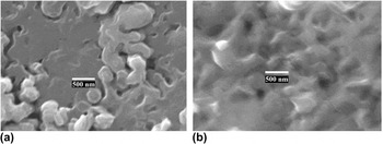
Top surface SEM images of films grown by MPAS show the surface ranges on a large scale from mostly flattened platelet surfaces with some more localized island growth to successive, textured irregular surfaces as seen in Fig. 2. The lower concentration films as seen in Fig. 2(a) grew in the a–b plane in more distinct, smooth, locally flat levels, creating plateau type of structures, and showing more large pores or noncontiguous areas than those for higher concentration. The higher concentration films as seen in Fig. 2(b) show a contiguous surface with large contoured bumps on the order of half a micron throughout. Note that the SEM images represent surface pictures, and smaller crystals may form at different sizes in and under the surface, and it is these embedded smaller crystals that are of more interest and have the most impact on TE performance.
Surface scanning electron microscope images of a (a) lower concentration film and (b) higher concentration film grown by MPAS.

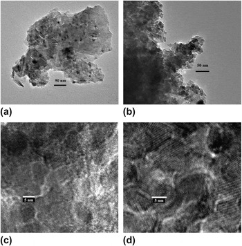
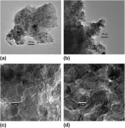
Transmission electron microscope (TEM) images give more information about the nanoparticles that form in the composite films as seen in Fig. 3, showing particles smaller than 50 nm. Figure 3(a) is the TEM image from a lower concentration deposition, and Fig. 3(b) is the TEM image from a higher concentration deposition.
Transmission electron microscopy (TEM) images of a (a) lower concentration film and (b) higher concentration film, which show that the nanoparticle boundaries are smaller than 50 nm. High-resolution TEM images show more clearly that (c) nanocrystalline grains for the lower concentration films are on the order of 5 nm and (d) nanocrystalline grains for a higher concentration are greater than 10 nm.

High-resolution TEM (HRTEM) images give more quantitative data about the nanocrystal grains that form inside the particle boundaries. Figure 3(c) is the HRTEM image from a lower concentration deposition, and many nanocrystals on the order of 5 nm in diameter can be seen. Figure 3(d) is the HRTEM image from a higher concentration deposition in which nanocrystals are clearly much larger than that in Fig. 3(c); the average size is greater than 10 nm in diameter, corresponding to an increase of a factor of 8 in the nanocrystal volume. The TEM images clearly support the creation of smaller nanocrystals with many more boundaries per unit volume in lower concentration films and larger particles with less boundaries per unit volume in higher concentration films. This trend of nanocrystal size correlating with precursor concentration was also seen in a previous MPAS study of ZnO nanoparticles.Reference Wangensteen, Dhakal, Merlak, Witanachchi, Phan, Srikanth and Mukherjee25
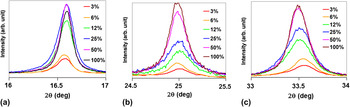
XRD scans also support the strong crystallinity of the films as seen in Fig. 4. The XRD scans seen in Figs. 4(a), 4(b), and 4(c) represent the (002), (003), and (004) planes of Ca3Co4O9, respectively. The scans shown were made from films of the same nominal thickness with varying molar concentrations, as previously described, and shows that the strength of the peaks increases with increasing molar concentration. Therefore, the crystallinity of the films increases with increasing precursor concentration.
X-ray diffraction (XRD) patterns of films varied by precursor concentration as prepared by the MPAS deposition technique in this study. XRD peaks seen in (a), (b), and (c) are centered around the (002), (003), and (004) planes of Ca3Co4O9, respectively.

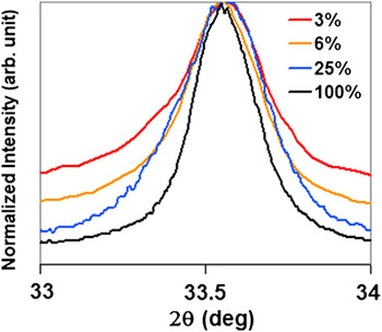
The difference in the peak line width for different concentrations can be seen in Fig. 5. It can be seen in the figure that films made from the smaller concentrations have larger peak widths that their higher concentration counterparts. Since these films are not just a collection of nanoparticles, but nanoparticles that are embedded within a larger crystal matrix, a Debye-Scherrer calculation is not appropriate. However, the relative trends are clearly evident.
XRD pattern of the high precursor concentration films compared with lower concentration films at the (004) plane of Ca3Co4O9 shows that lower concentrations broaden the peak.

B. Transport properties
Additional information gathered from electrical metrology techniques gives more important information about the films since they quantitatively relate to TE performance.
Resistivity and Seebeck measurements were carried out using a commercially made machine (ZEM-3; ULVAC Technologies, Inc., Methuen, MA). This machine measures the electrical conductivity by a four-point current-switching technique. In addition, the Seebeck coefficient was measured by a static direct-current method. Seebeck is determined from the slope of voltage difference versus temperature difference curve measured by two thermocouple probes. To avoid possible oxidation, the measurement was carried out in helium atmosphere. The accuracy of electrical resistivity and Seebeck coefficient measurements are 4 and 7%, respectively. Using the above techniques, the previously mentioned six samples were measured from room temperature to 700 K.
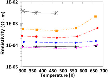
The resistivity plots of the films can be seen in Fig. 6. Overall, the resistivity of the samples changed over two orders of magnitude. It can be seen that the smallest concentration was not measured over the whole range due to the increase in sample resistivity with temperature beyond the instrument measurement range. The resistivity decreases significantly with the use of higher concentrations, which correlates to larger nanoparticles incorporated in the composite films. The magnitude of the conductivity of higher concentration films grown in this study is in the same range as that obtained by others using SPS methods. The explanation for the high conductivity seen in the higher concentration films, similarly, is due in part to the fusing together of smaller pieces as a result of the growth process. This result is very encouraging since there should be further room for optimization by changing the salt concentration, controlling the oxygen content, or doping. Others have seen a further large change in the conductivity when an aligned texture was induced in Ca3Co4O9.Reference Kwon, Jo, Ko, Kim, Bae, Koo, Jeong, Kim and Park27 In that study, the crystals were prepared first by a solid-state reaction followed by SPS and then further by a multisheet cofiring (MSC) technique. The MSC technique used by Kwon et al. was shown to greatly increase the degree of c-axis orientation, which was reflected in their very high conductivity, approaching that of single-crystal values.Reference Shikano and Funahashi28 Our best results are slightly less conductive, differing by ∼30% as compared with the MSC samples.
Resistivity of grown films. Colors and shapes refer to concentration percent of precursor: star = 0.75%, red circle = 3%, orange square = 6%, blue diamond = 25%, violet circle = 50%, and black triangle = 100%.

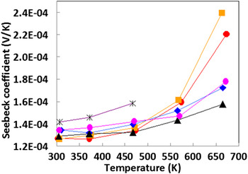
The Seebeck coefficients of the films are shown in Fig. 7. This material showed only a small change with concentration at temperatures below 550 K. The Seebeck coefficient decreased with films of increasing precursor concentrations, which reflected the incorporation of larger particles, containing less boundaries than films made from lower concentration. The trend, though evident, showed relatively small changes with exception of the most resistive films that showed large increases in the Seebeck coefficient.
Seebeck coefficient of grown films. Colors and shapes refer to concentration percent of precursor: star = 0.75%, red circle = 3%, orange square = 6%, blue diamond = 25%, violet circle = 50%, and black triangle = 100%.

At lower temperatures, the effective change in carrier concentration (n) as a function of precursor concentration reflects a small change in the Seebeck coefficient (as in Eq. 4) for the different samples. Therefore, the much larger corresponding change in conductivity for the samples (as seen in Fig. 6), is due to a change in mobility. This change in mobility is due to scattering events at the boundaries which are detrimental to conduction. These scattering events are more pronounced at the lower precursor concentrations with their corresponding higher interfaces per unit volume.
At higher temperatures, the samples show significant changes in both conductivity and the Seebeck coefficient. Initially, changes in the samples all happen at the same rates as the temperature increased. At higher temperatures (∼550 K), however, the conductivity encounters a significant rate of increase. Others have explained temperature changes in the conductivity of the TE material Ca3Co4O9 due to changes in the nature of charge transport in three separate regions representing metal-type dominated, three-dimensional variable range hopping (3D-VRH), and nearest-neighbor hopping, respectively.Reference Wang, Sui, Cheng, Wang and Su17, Reference Cheng, Sui, Wang, Wang and Su29 Here, the onset of 3D-VRH is seen after 400 K following the metal–semiconductor transition previously seen by others at ∼380 K.Reference Cheng, Sui, Wang, Wang and Su29 In those cases, the conductivity of doped samples was seen to increase as a function of temperature in contrast to the decrease observed in our undoped samples. In our work, the onset of nearest neighbor hopping is seen after 550 K. It appears that nearest neighbor hopping is detrimentally affected by boundaries. When considering the impact of the boundaries caused by particles, one has to consider both the distance between them and their size that affect the number of scattering events and the heights of the modeled energy barriers, respectively.Reference Woods, Popescu, Martin, Nolas, Yang, Nolas, Koumoto and Grin30 As seen from the TEM images, the greater number of boundaries in the lower precursor concentration samples would explain the correspondingly larger conductivity changes at higher temperatures seen in those samples. This is consistent with the reduction of conductivity by incorporating nanoparticles was seen by others in the investigation of PbTe nanodot superlattices in which the reduction was also attributed to boundaries.Reference Vineis, Harman, Calawa, Walsh, Reeder, Singh and Shakouri31
The upward trend for the Seebeck coefficient previously noted remains the same as a function of the temperature but increases in slope going to higher temperature zones for the lower precursor concentration films. In a study of silicon nanowires, smaller sizes were also seen to increase the Seebeck coefficient and follow a nearly linear upward trend with decreasing size until becoming nonlinear at the very smallest scales.Reference Shi, Yao, Zhang and Li32 The enhancement of the Seebeck coefficient of the nanowires was explained as a narrowing of the density of states at the smaller scales. The Seebeck coefficient has also been shown in several materials to be related to the effective mass.Reference Wang, Sui, Cheng, Wang and Su17, Reference Ishida, Cao, Morioka, Inoue and Kita33–Reference Kinemuchi, Nakano, Mikami, Kobayashi, Watari and Hotta35 Specifically, in Ca3Co4O9, increases in the effective mass with increasing temperature can be explained by related lattice changes at critical points, which in turn affect the electronic correlation.Reference Kwon, Jo, Ko, Kim, Bae, Koo, Jeong, Kim and Park27, Reference Brinkman and Rice36 With increased effective mass, the carrier concentration is decreased, and thus the Seebeck coefficient is increased.Reference Wang, Sui, Cheng, Wang, Su and Fan37 For that study, the second term in Eq. (4) had an additional strong influence on the doped samples, further enhancing the Seebeck coefficient, and producing the best samples. In our case, with all undoped samples, an additional possible explanation of the strong increase in Seebeck coefficient comes from increased barrier height after the lattice changes leading to enhanced scattering of low-energy electrons, increasing the thermal energy carried per charge carrier.
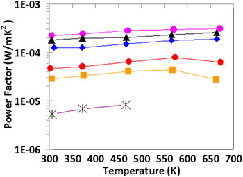
Combining the results of the resistance measurements with the Seebeck results as from Eq. (2) gives the PF as shown in Fig. 8. The PF followed the same trend as the resistivity in that the most conductive films resulted in the highest PFs. The value of the PFs seen here for the highest concentration films (220 μW/mK2), that is those greater than 200 μW/mK2, meet or exceed those prepared by using other one-step processes.
Power factor of grown films. Colors and shapes refer to concentration percent of precursor: star = 0.75%, red circle = 3%, orange square = 6%, blue diamond = 25%, violet circle = 50%, and black triangle = 100%.

III. CONCLUSIONS
The growth and characterization of nanocomposite Ca3Co4O9 thin films using a MPAS deposition technique have been demonstrated for the first time. The process showed that the incorporation of a microwave improved results in both morphology and, especially, electronic properties than those grown previously by LASP technique. The films containing larger crystals had the most desirable properties with regard to large PF. Since these films correspond to lower Seebeck coefficients but much higher conductivities, this suggests that the conductivity is the most critical factor in maximizing the power factor for this material. Theoretical predictions of an optimum size of particles for high PF suggests that the optimum size of particles is not just creating the smallest crystal with the greatest number of boundaries, since the smaller size causes a large degradation of the conductivity. Extending the current study to higher temperatures or to include higher precursor concentrations can provide data to verify the optimum size theory. However, for the concentrations and temperature ranges from this study, we can conclude that the higher concentration of the precursor resulted in a larger PF. Although executed as a one-step process, this deposition method has a similar outcome as SPS that combines nanoparticulates together without completely melting all of them, thus keeping the phonon scattering benefits while improving the electrical conduction. The composite films grown by this process are made up of particles containing multiple nanograins whose resulting structure consequently had a substantial effect on both the conductivity and the PF.