1. Introduction
In recent years, various legged mobile robots have been developed to use for outdoor exploration and post-disaster rescue. In previous studies, most of the legged robots have series structures [Reference Farshidian, Jelavic, Satapathy, Giftthaler and Buchli1]. With the rapid development of motion control and gait planning algorithms, the parallel leg structure has become a research hotspot in the field of robots due to its closed-loop structure, good rigidity, accurate movement, and strong carrying capacity [Reference Chen, Hu, Zhang and Qi2]. In this paper, a novel parallel mobile robot is designed for rescue after disaster. The invariably horizontal control of parallel mobile robot is to ensure the motion stability of the robot and avoid the secondary injury of the rescued wounded. The traditional kinematic control methods are often difficult to meet the requirements of the invariably horizontal control of the parallel mobile rescue robot. With the development of intelligent bionic control technology, many methods have become effective ways to solve this problem such as CPG model, neural network, and reinforcement learning [Reference Niu, Xu, Ren and Wang3–Reference Du, Fnadi and Benamar5].
CPG exists in the central nervous system of vertebrates or ganglia of invertebrates. It is mainly responsible for generating rhythmic movement patterns of animals in real time such as crawling, flying, swimming, and running [Reference Delcomyn6]. Inspired by the stability and adaptability of biological CPG, the artificial CPG model has been widely studied in the motion control of the legged robot. The notable examples include the studies of Chung [Reference Chung, Hou and Hsu7], Zhong et al. [Reference Zhong, Chen, Jiao, Li and Deng8], Yu et al. [Reference Yu, Gao and Deng9], and Bal [Reference Bal10]. Through these studies, it can be found that the bionic method can greatly simplify the locomotion control problem under the coordination of multiple legs. However, it is difficult to find a set of suitable parameters to generate the desired motion pattern in the huge parameter search space. Therefore, it is necessary to optimize the model parameters when constructing the CPG control model of the legged robots.
The CPG parameters in many studies are determined by experience. Some studies combined intelligent optimization methods and data-driven optimization methods. Cui et al. [Reference Wang, Cui, Sun and Gao11] used multi-objective genetic algorithm to optimize the CPG model and carried out experiments on the hexapod robot platform, which significantly improved the motion ability of the robot. Besides, Lee et al. [Reference Kim, Jorgensen, Lee, Ahn, Luo and Sentis12] used Non-Dominated Sorting Genetic Algorithm for multi-objective optimization to generate the walking trajectory of biped robot. In the work of Juang et al. [Reference Juang, Chang and Hsiao13], the PSO algorithm based on symbiotic species was proposed to automatically optimize the motion parameters of hexapod robot. On this basis, Ouyang et al. [Reference Ouyang, Chi, Pang, Liang and Ren14] used the combination of PSO algorithm and deep learning algorithm to optimize the CPG model parameters, which promoted the effectiveness of the control method. In the previous work of our research team, a CPG gait control algorithm is proposed for a dual Stewart parallel mobile robot via the optimized motion parameters by employing genetic algorithms(GA) [Reference Liu, Chen, Wu and Zhang15, Reference Jia, Chen, Zhang, Wu and Li16].
In this work, the robot designed by us is a biped parallel mobile robot based on Stewart platform. The structure of the robot is mainly composed of two inverted and cross-assembled 6-DOF Stewart platforms. The upper platform of the robot is responsible for the placement of the wounded, and the two lower platforms are responsible for the overall movement of the robot. In order to improve the previous model based on GA and CPG method, the kinematics model is optimized by using the PSO-CPG algorithm. According to the structure of the robot, the dynamic model of the robot is established by using the Kane equation, which provides the mechanical basis for the feedback of the control signal. Finally, the invariably horizontal control of the upper platform on the parallel mobile rescue robot is realized.
The contributions of this paper are listed as follows: (1) A kinematics optimization method based on PSO-CPG algorithm is proposed, which solves the displacement hysteresis problem of each electric cylinder of the robot. Compared with the step length optimization CPG method based on GA presented in previous work, this method effectively improves the slight impact of legs landing during the transition phase of the motion cycle. (2) The dynamic model of the parallel mobile rescue robot is established for the control system based on the Kane equation. (3) The prototype experiment is completed based on the theories 1 and 2. The invariably horizontal motion control of the platform on the robot was realized, which ensures the stability and safety of the robot.
This paper is organized as follows: Section 2.1 describes the robot structure of the biped parallel robot and Section 2.2 explains motion process of the robot. Section 3 describes the control strategy of invariably horizontal state for the biped parallel robot. The PSO algorithm is proposed to optimize the parameters of the Hopf model in Section 3.3. Section 4 analyzes the dynamic model of the parallel mobile rescue robot. Simulation experiment and prototype experiment are given in Sections 5. Section 6 summarizes the achievements of this work.
2. Mechanical structure and motion modeling of the biped parallel robot
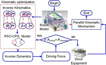
In this section, the mechanical structure of parallel mobile rescue robot is illustrated and the motion modeling of the system is derived. The basic logic diagram of the parallel mobile rescue robot is shown in Fig. 1. Firstly, the kinematics inverse solution is derived according to the structural characteristics of the robot. The displacement of each electric cylinder is calculated. Furthermore, the kinematic model is optimized by the PSO-CPG algorithm and the optimized kinematic parameters of the robot are obtained. Then, the optimized kinematic parameters are brought into the dynamic model to solve the driving force of each electric cylinder and compared with the allowable thrust of the electric cylinder. If it is less than the allowable thrust of the electric cylinder, the driving force signal is transmitted to the driver to drive the parallel mechanism. If the calculated driving force exceeds the allowable thrust of the electric cylinder, it is necessary to return to the kinematics optimization part to recalculate the motion parameters until the driving force of the electric cylinder is less than the allowable thrust to complete the iteration. Finally, the invariably horizontal motion of the platform on the parallel mobile rescue robot is achieved.
Basic logic diagram of the parallel mobile rescue robot.

2.1. Mechanical structure
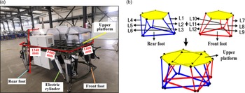
The biped parallel mobile robot is mainly composed of five parts, including the upper platform, the front foot, the rear foot, eighteen electric cylinders. The front and the rear feet of the robot are driven by electric cylinders. The upper platform is horizontal during movement. The basic structure of the robot is shown in Fig. 2.
Structure diagram of the biped parallel robot.

The robot structure is composed of two 6-DOF Stewart parallel platforms, which are assembled inverted and cross-symmetrically, as shown in Fig. 2. In the picture, the red part is the front foot of the parallel mobile rescue robot. The blue part is the rear foot of the parallel mobile rescue robot. The yellow part is the upper platform of the robot. The structure of the front and rear feet is same.
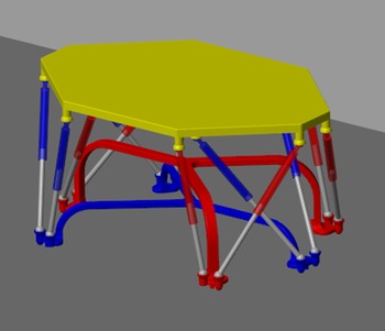
There may be some structural interference problems between the front and the rear feet. The two mechanisms need to be optimized to avoid interference. First, the front foot structure is adjusted to the star arch foot structure. Secondly, the rear foot is also adjusted to the star arch foot structure but the height of the arch foot should be lower than that of the front foot. The specific height of the front and the rear arch feet are determined by the stride of the robot. The 3D structure of the robot is shown in Fig. 3.
3D structure of the biped parallel robot.

2.2. Motion modeling
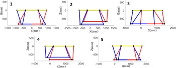
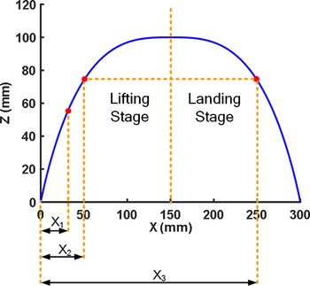
The motion of the parallel mobile rescue robot is realized by the relative displacement of two sets of Stewart platforms. As shown in Fig. 4, the abscissa is X-axis and the ordinate is Z-axis. When the robot moves along the X-axis, the front foot of the robot rises along the Z-axis according to the planned trajectory. When the front foot reaches the preset lifting height, it moves along the straight line of the X-axis for a certain distance and then falls along the Z-axis. In the whole stage from lifting to falling of the front foot, the rear foot is responsible for supporting and pushing the bearing platform on the robot forward by half of the step length along the X-axis. After the front foot finishes a periodic motion, the rear foot then repeats the motion of the front foot. In the whole stage from lifting to falling of the rear foot, the front foot is responsible for supporting and pulling the bearing platform on the robot forward by half of the step length along the X-axis. Then, the gait movement of the parallel mobile rescue robot in one cycle is completed.
Motion analysis in X and Z directions.

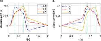
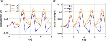
According to the basic motion mode of the parallel mobile rescue robot, the displacement change curve of the electric cylinders can be obtained, as shown in Fig. 5. The displacement of each electric cylinder does not reach the peak of the displacement change simultaneously. The electric cylinders 7 and 9 lag electric cylinder 8 to reach the peak of displacement change for the front foot. The electric cylinder 5 lags electric cylinders 4 and 6 to reach the peak of displacement change for the rear foot. Therefore, the bearing platform on the robot cannot move at a constant level in the process of motion. Aiming at this problem, the Hopf model of the parallel mobile rescue robot is established.
(a) Displacement variation curve of electric cylinder of the front foot. (b) Displacement variation curve of electric cylinder of the rear foot.

3. Control strategy
In the process of motion, the parallel mobile rescue robot needs to constantly adjust the displacement of the electric cylinder to achieve invariably horizontal motion of the upper platform on parallel mobile robot. However, it is difficult to achieve the purpose of invariably horizontal motion of the upper platform based on the traditional kinematics control. In this paper, the kinematics optimization method based on PSO-CPG algorithm is presented and the dynamic model is established, which solves the control problem of invariably horizontal motion of the upper platform on the parallel mobile rescue robot.
3.1. Hopf oscillator model
At present, various types of CPG models have been applied in the field of robotics. The Hopf oscillator is the model with fewer parameters. It is a simple mathematical model of CPG. The Hopf oscillator is used in the control of invariably horizontal state for the biped parallel robot. The mathematical model of the Hopf oscillator is shown as follows.
 \begin{equation} \left \{{\begin{array}{*{20}{l}}{\dot x = \alpha \left ({\mu -{r^2}} \right )x - \omega y}\\[6pt]{\dot y = \alpha \left ({\mu -{r^2}} \right )y + \omega x} \end{array}} \right. \end{equation}
 \begin{equation} \left \{{\begin{array}{*{20}{l}}{\omega = \dfrac{{{\omega _{\text{down}}}}}{{{e^{ - ay}} + 1}} + \dfrac{{{\omega _{\text{up}}}}}{{{e^{ay}} + 1}}}\\[12pt]{{\omega _{\text{down}}} = \dfrac{{1 - \beta }}{\beta }{\omega _{\text{up}}}} \end{array}} \right. \end{equation}
where
 $x$
and
 $y$
are the state variables of the oscillator,
 $r = \sqrt{{x^2} +{y^2}}$
is the radius of the limit cycle after the oscillator is stably output;
 $\mu$
determines the amplitude of the oscillator,
 $A = \sqrt{\mu }, \mu \gt 0$
,
 $\mu$
is the parameter of the Hopf oscillator, and
 $A$
represents the amplitude of the output signal [Reference Righetti, Buchli and Ijspeert17]. It is worthy of note that
 $\mu$
and A are dimensionless parameters [Reference Righetti, Buchli and Ijspeert17].
 $\omega$
is the frequency of the oscillator,
 $\omega _{\text{down}}$
and
 $\omega _{\text{up}}$
are the frequency of the robot leg support phase and swing phase respectively;
 $\alpha$
is used to control the speed at which the oscillator converges to the limit cycle, which is a positive integer;
 $\beta$
is the duty factor, that is, the ratio of the time when the robot’s leg is supported on the ground to the gait period is generally 0.5 and 0.75. For the robot structure in this article,
 $\beta = 0.5$
.
3.2. Hopf oscillator model of the parallel robot
The two output signals of an oscillator can be transmitted to the hip and knee joints with rhythmic motion characteristics for the legged robot with a series structure. However, the hip and knee joints cannot be found directly in the parallel mobile rescue robot, so it needs to be processed according to the end equation of feet. The trajectory equation of the foot end is as shown in Eq. (3). When the foot moves in the period of 0 to T/2, it is just in the leg lifting stage of the robot, and the position in the X direction is directly solved, as shown in Eq. (4). When the motion period of the foot is between T/2 and T, it is just in the landing stage of the robot. According to the symmetry relationship of the foot trajectory, as shown in Fig. 6. The displacement in the X direction is equal to the step length minus the current inverse function value of Z, see Eq. (5) and Fig. 6.
 \begin{equation} \begin{array}{l} x = S\left [{\dfrac{t}{T} - \dfrac{1}{{2\pi }}\sin\left ({\dfrac{{2\pi t}}{T}} \right )} \right ]\\[1.5em] z = \left \{{\begin{array}{*{20}{l}}{2A\left [{\dfrac{t}{T} - \dfrac{1}{{4\pi }}\sin\left ({\dfrac{{4\pi t}}{T}} \right )} \right ];\,\, 0 \le t \lt \dfrac{T}{2}}\\[1.5em]{2A\left [{1 - \dfrac{t}{T} - \dfrac{1}{{4\pi }}\sin\left ({\dfrac{{4\pi t}}{T}} \right )} \right ];\,\, \dfrac{T}{2} \le t \lt T} \end{array}} \right. \end{array} \end{equation}
where
 $S$
is the step size.
 $A$
is the amplitude of the Hopf signal.
 $T=\dfrac{\pi \beta }{(1-\beta ){{\omega }_{\text{up}}}}+\dfrac{\pi }{{{\omega }_{\text{up}}}}={{T}_{m}}\cdot \beta$
(
 ${T}_{m}$
is the gait period).
Analytic diagram of the X direction displacement inverse solution.

 \begin{equation}{x_1} ={z_1}^{-1} \end{equation}
 \begin{equation}{x_3} = S -{z_2}^{-1} \end{equation}
The CPG network applied to the robot in this paper is composed of two Hopf oscillators as gait pattern generators. There is a certain phase relationship during the alternate movement of two legs. Therefore, it is necessary to determine the corresponding two sets of mutually inhibiting CPG signals. In one movement period, the movement time of the two feet is set to be equal, and the phase difference of the biped oscillator is
 $\pi$
. The specific CPG network can be expressed by the following differential equation.
 \begin{equation} \left \{ \begin{array}{l} \left [{\begin{array}{*{20}{l}}{{{\dot x}_i}}\\{{{\dot y}_i}} \end{array}} \right ] = \left [{\begin{array}{*{20}{c}}{\alpha \left ({\mu - r_i^2} \right )}&\quad{ -{\omega _i}}\\{{\omega _i}}&\quad{\alpha \left ({\mu - r_i^2} \right )} \end{array}} \right ]\left [{\begin{array}{*{20}{c}}{{x_i}}\\{{y_i}} \end{array}} \right ] + \sum \limits _{j = 1}^2 \boldsymbol{{R}} \left ({\varphi _i^j} \right )\left [{\begin{array}{*{20}{l}}{{x_j}}\\{{y_j}} \end{array}} \right ],i = 1,2\\{X_i} ={x_i}\\{Z_i} = \left \{{\begin{array}{*{20}{l}}{ - \text{sgn}(\varphi )\frac{1}{2}{y_i},{y_i} \le 0}\\{0,{y_i} \gt 0} \end{array}} \right. \end{array} \right. \end{equation}
where
 $\boldsymbol{{R}}(\varphi _{i}^{j})$
represents the rotation matrix of oscillator
 $j$
relative to oscillator
 $i$
, and
 $\varphi _{i}^{j}$
represents the relative phase from oscillator
 $i$
to oscillator
 $j$
. The rotation transformation matrix is shown in Eq. (7) as follows.
 \begin{equation} \boldsymbol{{R}}(\varphi _i^j) = \left [{\begin{array}{*{20}{l}}{\cos{\varphi _{ij}}}&\quad{ - \sin{\varphi _{ij}}}\\{\sin{\varphi _{ij}}}&\quad{\cos{\varphi _{ij}}} \end{array}} \right ] = \left [{\begin{array}{*{20}{c}}{\cos\!(1 - \beta )\pi }&\quad{ - \sin\!(1 - \beta )\pi }\\{\sin\!(1 - \beta )\pi }&\quad{\cos\!(1 - \beta )\pi } \end{array}} \right ] \end{equation}
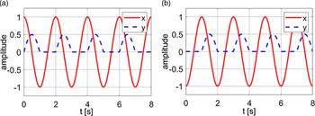
By substituting Eq. (7) into Eq. (6), the control signals of the front and rear feet of the robot can be obtained, as shown in Fig. 7.
Control signal in the single cycle: (a) CPG signal of the front foot. (b) CPG signal of the rear foot. (In the figure, x represents the displacement control signal in the Z direction of the robot’s foot end; y represents the displacement control signal in the X direction of the robot’s foot end).

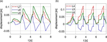
The displacement curve of the electric cylinder adjusted by CPG can be obtained as shown in Fig. 8. It can be seen that the change of displacement can reach the maximum value at the same time from Fig. 8. The displacement hysteresis problem of the electric cylinder is solved. However, before optimizing the parameters of the Hopf model, there is problem of mutation in the displacement change, which will reduce the stability of the motion for the parallel mobile rescue robot. Therefore, the parameters in the Hopf model need to be optimized.
Displacement curve of the electric cylinders after adjustment: (a) Displacement curve of the front foot electric cylinders. (b) Displacement curve of the rear foot electric cylinders.

3.3. Parameters optimization of Hopf model
Optimizing the parameters in CPG model can make the robot move smoothly. In this section, the PSO algorithm will be used to optimize the parameters in the Hopf model. The motion speed of the biped parallel robot can be determined by the following formula.
 \begin{equation} v = S\omega \end{equation}
 \begin{equation} \left \{{\begin{array}{*{20}{l}}{\omega = \dfrac{{{\omega _{\text{down}}}}}{{{e^{ - ay}} + 1}} + \dfrac{{{\omega _{\text{up}}}}}{{{e^{ay}} + 1}}}\\[12pt] \begin{array}{l}{\omega _{\text{down}}} = \dfrac{{1 - \beta }}{\beta }{\omega _{\text{up}}}\\[12pt] \beta = \dfrac{{{T_{\text{down}}}}}{T} \end{array} \end{array}} \right. \end{equation}
where
 $v$
represents the walking speed of the robot,
 $S$
represents the step length,
 $\omega$
represents the step frequency, and
 $T_{\text{down}}$
is the period of the leg support item. From Eq. (3), the step frequency is related to the height of the leg lift; hence, the amplitude and frequency in Hopf are mainly optimized. The two parameters need to satisfy the following relationship.
 \begin{equation} \left \{{\begin{array}{*{20}{l}}{{\omega _{\min }} \le{\omega _i} \le{\omega _{\max }}}\\{{A_{\min }} \le{A_i} \le{A_{\max }}} \end{array}} \right. \end{equation}
Based on the structural characteristics of the robot, there are the following constraints as shown in Table I.
Parameters constraint range.

The fitness function of PSO algorithm is used to evaluate the advantages of a single population. It directly affects the convergence speed and optimization results. In order to achieve the comprehensive stable state, the variance of two output signals is selected as the fitness function, as shown in Eq. (11).
 \begin{equation} f(x) = \left \{{\begin{array}{*{20}{l}}{\text{var}\!\left ({{x_1},{x_2}} \right )}\\{\text{var}\!\left ({{y_1},{y_2}} \right )} \end{array}} \right. \end{equation}
where
 $f(x)$
is the fitness function.
 $x_i$
and
 $y_i$
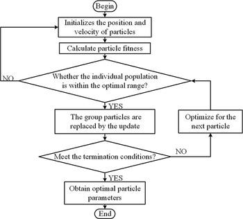
respectively represent the output signals of the front and rear feet. The smaller the variance, the more stable the waveform and the better the adaptability. The flow chart of CPG parameter optimization based on PSO algorithm is shown in Fig. 9.
CPG parameter optimization flow chart.

4. Dynamic analysis of the biped parallel robot
The dynamic model of the parallel mobile rescue robot will be established in this section. The establishment of the dynamic model of the parallel mobile rescue robot is to provide the mechanical basis for the feedback of the control signal. Since the legs of the robot are two Stewart mechanisms with the same structure, the dynamic model of the robot is a complex model with multiple degrees of freedom, multiple variables, and a high degree of nonlinearity. The Kane equation is used to establish the Stewart single-leg dynamic equation.
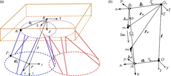
For the convenience of analysis, a relative dynamic coordinate system
 ${{\textit{O}}}-\textit{xyz}$
is established at any point on the robot’s feet. And a relative static coordinate system
 ${{\textit{O}}}_1-{{\textit{XYZ}}}$
(that is, the inertial rectangular coordinate system) is located on any point on the robot carrying platform, as shown in Fig. 10(a). A schematic diagram of the limb
 $i$
is shown in Fig. 10(b). A coordinate system
 ${{{\textit{B}}}_{{\textit{i}}}}-{x_i}{y_i}{z_i}$
is established at the hinge point
 $B_i$
on the limb
 $i$
, and a coordinate system
 ${{\textit{A}}}_{{\textit{i}}}-{x_i}{y_i}{z_i}$
is located on the hinge point
 $A_i$
of the lower limb
 $i$
. In the following, the inverse kinematics problem and dynamics problem are analyzed according to the established coordinate system.
Schematic diagram of the structure.

4.1. Inverse solution analysis of position
Before solving the dynamics, it is necessary to analyze the inverse position solution of the robot. As shown in Fig. 10(b), according to the vector relationship, the position vector of the lower hinge point
 $A_i$
can be obtained from Eq. (12).
 \begin{equation}{\boldsymbol{{b}}_i} +{l_i}{\boldsymbol{{n}}_i} = \boldsymbol{{t}} +{\boldsymbol{{a}}_i} \end{equation}
where
 \begin{equation}{\boldsymbol{{a}}_i} ={}^W{\boldsymbol{{R}}_B}^A{\boldsymbol{{a}}_i} \end{equation}
 \begin{equation}{\boldsymbol{{n}}_i} = \frac{{\boldsymbol{{t}} +{\boldsymbol{{p}}_i} -{\boldsymbol{{b}}_i}}}{{{l_i}}} \end{equation}
 \begin{equation}{l_i} = \left \|{\boldsymbol{{t}} +{\boldsymbol{{a}}_i} -{\boldsymbol{{b}}_i}} \right \| \end{equation}
 ${}^W$
 ${\boldsymbol{{R}}}_{B}$
is the rotation transformation matrix from relative dynamic coordinate system
 ${\mathrm{O}}-xyz$
to relative static coordinate system
 ${{\textit{O}}}_1-{\textit{XYZ}}$
.
 \begin{equation}{}^W{\boldsymbol{{R}}_B} = \left [{\begin{array}{*{20}{c}}{c\alpha c\gamma - s\alpha c\beta s\gamma }&{ - c\alpha c\gamma - s\alpha c\beta s\gamma }&{s\alpha s\beta }\\{s\alpha c\gamma + c\alpha c\beta s\gamma }&{ - s\alpha s\gamma + c\alpha c\beta c\gamma }&{ - c\alpha s\beta }\\{s\beta s\gamma }&{s\beta c\gamma }&{c\beta } \end{array}} \right ] \end{equation}
According to Fig. 10(b), the positions of the mass center of the upper cylinder and the mass center of the lower piston rod are shown in Eq. (17) and Eq. (18), respectively.
 \begin{equation}{\boldsymbol{{r}}_{ui}} ={\boldsymbol{{b}}_i} +{\boldsymbol{{h}}_{ui}} \end{equation}
 \begin{equation}{\boldsymbol{{r}}_{di}} ={\boldsymbol{{t}}} +{\boldsymbol{{a}}_i} +{\boldsymbol{{h}}_{di}} ={\boldsymbol{{b}}_i} +{l_i}{n_i} +{\boldsymbol{{h}}_{di}} \end{equation}
According to the vector relationship, the position vector of foot centroid can be obtained as in Eq. (19).
 \begin{equation}{\boldsymbol{{r}}_c} ={\boldsymbol{{t}}} +{}^W{\boldsymbol{{R}}_B}{\boldsymbol{{c}}} \end{equation}
where
 $\boldsymbol{{c}}={{\left [ \begin{matrix}{{c}_{x}} &{{c}_{y}} &{{c}_{z}} \\ \end{matrix} \right ]}^{\textrm{T}}}$
is the position vector of the foot centroid in the coordinate system
 ${O}-xyz$
.
4.2. Inverse solution analysis of velocity
 $v_{{A_i}}$
represents the speed of lower hinge
 $A_i$
, which is calculated by following formula.
 \begin{equation}{\boldsymbol{{v}}_{{A_i}}} ={\boldsymbol{{v}}_O} +{\boldsymbol{\omega } _O} \times{\boldsymbol{{a}}_i} ={l_i}{\boldsymbol{\omega } _i} \times{\boldsymbol{{n}}_i} +{\dot l_i}{\boldsymbol{{n}}_i} \end{equation}
where
 $\boldsymbol{{v}}_O$
represents the translation speed of
 $O$
point on the foot in the coordinate system
 ${{\textit{O}}}_1-{{\textit{XYZ}}}$
;
 $\omega _O$
represents the rotational angular velocity of the foot in the coordinate system
 ${{\textit{O}}}_1-{{\textit{XYZ}}}$
.
 $\omega _i$
is the angular velocity of the
 $i$
th limb,
 $\dot l_i$
represents the telescopic speed of limb
 $i$
.
 \begin{equation}{\dot l_i} = \frac{1}{{{l_i}}}\left [{{{\left ({t +{\boldsymbol{{p}}_i} -{\boldsymbol{{b}}_i}} \right )}^T}{{\left ({{\boldsymbol{{p}}_i} \times \left ({\boldsymbol{{t}} -{\boldsymbol{{b}}_i}} \right )} \right )}^T}} \right ]\left [{\begin{array}{*{20}{l}}{{\boldsymbol{{v}}_O}}\\{{\boldsymbol{\omega } _O}} \end{array}} \right ] \end{equation}
Suppose that the limb
 $i$
of the Stewart platform on robot cannot rotate around its own axis, that is
 \begin{equation}{\boldsymbol{\omega }_i} \cdot{\boldsymbol{{n}}_i} = 0 \end{equation}
The rotational angular speed of limb
 $i$
is
 \begin{equation}{\boldsymbol{\omega }_i} = \frac{{\boldsymbol{{n}}_i} \times{\boldsymbol{{v}}_{A_i}}}{l_i} \end{equation}
The translational velocity
 $\boldsymbol{{v}}_{u_i}$
and
 $\boldsymbol{{v}}_{d_i}$
of the center of mass of the cylinder barrel and the center of mass of the piston rod on the limb
 $i$
are, respectively.
 \begin{equation}{\boldsymbol{{v}}_{ui}} ={\boldsymbol{\dot{\boldsymbol{{r}}}}_{ui}} ={\boldsymbol{\dot \omega }_i} \times{\boldsymbol{{h}}_{ui}} \end{equation}
 \begin{equation}{\boldsymbol{{v}}_{di}} ={\boldsymbol{\dot{\boldsymbol{{r}}}}_{di}} ={l_i}{\boldsymbol{\dot \omega }_i} \times{\boldsymbol{{n}}_i} +{\dot l_i}{\boldsymbol{{n}}_i} +{\boldsymbol{\omega }_i} \times{\boldsymbol{{h}}_{di}} \end{equation}
In order to simplify the equation, a Jacobian matrix between velocities needs to be established. First, defining the Jacobian matrix
 $\boldsymbol{{J}}$
of the extension speed of the piston rod and the foot generalized speed as
 \begin{equation} \dot l ={\left [{\begin{array}{*{20}{l}}{{{\dot l}_1}}&{{{\dot l}_2}}&{{{\dot l}_3}}&{{{\dot l}_4}}&{{{\dot l}_5}}&{{{\dot l}_6}} \end{array}} \right ]^T} = \boldsymbol{{J}}\left [{\begin{array}{*{20}{l}}{{\boldsymbol{{v}}_{\rm{O}}}}\\{{\boldsymbol{\omega } _{\rm{O}}}} \end{array}} \right ] = \boldsymbol{{J}}{\boldsymbol{\dot{\boldsymbol{{x}}}}_O} \end{equation}
where
 $\boldsymbol{\dot{\boldsymbol{{x}}}}_O = \left [ \begin{matrix}{\boldsymbol{{v}}_{O}} \\{\boldsymbol{\omega }_{O}} \\ \end{matrix} \right ]$
is the generalized velocity of the foot coordinate system. Combining Eq. (10), it can be obtained that the Jacobian matrix
 $\boldsymbol{{J}}$
is
 \begin{equation} \boldsymbol{{J}} ={\left [{\begin{array}{*{20}{l}}{\frac{1}{{{l_1}}}\left [{{{\left ({\boldsymbol{{t}} +{\boldsymbol{{a}}_1} -{\boldsymbol{{b}}_1}} \right )}^T}} \right .}&{\left .{{{\left ({{\boldsymbol{{a}}_1} \times \left ({\boldsymbol{{t}} -{\boldsymbol{{b}}_1}} \right )} \right )}^T}} \right ]}\\[3pt]{\frac{1}{{{l_2}}}\left [{{{\left ({\boldsymbol{{t}} +{\boldsymbol{{a}}_2} -{\boldsymbol{{b}}_2}} \right )}^T}} \right .}&{\left .{{{\left ({{\boldsymbol{{a}}_2} \times \left ({\boldsymbol{{t}} -{\boldsymbol{{b}}_2}} \right )} \right )}^T}} \right ]}\\[3pt]{\frac{1}{{{l_3}}}\left [{{{\left ({\boldsymbol{{t}} +{\boldsymbol{{a}}_3} -{\boldsymbol{{b}}_3}} \right )}^T}} \right .}&{\left .{{{\left ({{\boldsymbol{{a}}_3} \times \left ({\boldsymbol{{t}} -{\boldsymbol{{b}}_3}} \right )} \right )}^T}} \right ]}\\[3pt]{\frac{1}{{{l_4}}}\left [{{{\left ({\boldsymbol{{t}} +{\boldsymbol{{a}}_4} -{\boldsymbol{{b}}_4}} \right )}^T}} \right .}&{\left .{{{\left ({{\boldsymbol{{a}}_4} \times \left ({\boldsymbol{{t}} -{\boldsymbol{{b}}_4}} \right )} \right )}^T}} \right ]}\\[3pt]{\frac{1}{{{l_5}}}\left [{{{\left ({\boldsymbol{{t}} +{\boldsymbol{{a}}_5} -{\boldsymbol{{b}}_5}} \right )}^T}} \right .}&{\left .{{{\left ({{\boldsymbol{{a}}_5} \times \left ({\boldsymbol{{t}} -{\boldsymbol{{b}}_5}} \right )} \right )}^T}} \right ]}\\[3pt]{\frac{1}{{{l_6}}}\left [{{{\left ({\boldsymbol{{t}} +{\boldsymbol{{a}}_6} -{\boldsymbol{{b}}_6}} \right )}^T}} \right .}&{\left .{{{\left ({{\boldsymbol{{a}}_6} \times \left ({\boldsymbol{{t}} -{\boldsymbol{{b}}_6}} \right )} \right )}^T}} \right ]} \end{array}} \right ]_{6 \times 6}} \end{equation}
The translational velocity
 $\boldsymbol{{v}}_C$
at the center of mass
 $C$
of the foot is
 \begin{equation}{\boldsymbol{{v}}_C} ={\boldsymbol{\dot{\boldsymbol{{r}}}}_C} = \boldsymbol{\dot{\boldsymbol{{t}}}} +{\boldsymbol{\omega }_O} \times \boldsymbol{{c}} ={\boldsymbol{{v}}_O} +{\boldsymbol{\omega }_O} \times \boldsymbol{{c}} ={\boldsymbol{{J}}_{C1}}{\boldsymbol{\dot{\boldsymbol{{x}}}}_O} \end{equation}
where
 $\boldsymbol{{J}}_{C1}$
is the speed Jacobian matrix derived from the centroid of the foot.
 \begin{equation}{\boldsymbol{{J}}_{C1}} = \left ({\begin{array}{*{20}{c}}{{\boldsymbol{{E}}_{3 \times 3}}}&{\left [{ - c \times } \right ]} \end{array}} \right ) = \left [{\begin{array}{*{20}{c}} 1&\quad 0&\quad 0&\quad 0&\quad {{c_z}}&\quad { -{c_y}}\\ 0&\quad 1&\quad 0 &\quad { -{c_z}}&\quad 0&\quad {{c_x}}\\ 0&\quad 0&\quad 1& \quad {{c_y}}&\quad { -{c_x}}&\quad 0 \end{array}} \right ] \end{equation}
The velocity
 $\boldsymbol{{v}}_{A_i}$
at the lower hinge point
 $A_i$
, the rotational angular velocity
 $\boldsymbol{\omega }_i$
of the limb
 $i$
, the translational velocity
 $\boldsymbol{{v}}_{u_i}$
and
 $\boldsymbol{{v}}_{d_i}$
of the center of mass of the cylinder end and the center of mass of the piston rod end can all be rewritten in the form of the Jacobian matrix.
 \begin{equation}{\boldsymbol{{v}}_{{A_i}}} ={\boldsymbol{{J}}_{A_i}}{\boldsymbol{\dot{\boldsymbol{{x}}}}_O} \end{equation}
 \begin{equation}{\boldsymbol{{J}}_{A_i}} = \left ({\begin{array}{*{20}{c}}{{\boldsymbol{{E}}_{3 \times 3}}}&{\left [{ -{\boldsymbol{{a}}_i} \times } \right ]} \end{array}} \right ) = \left [{\begin{array}{*{20}{c}} 1&\quad 0&\quad 0&\quad 0&\quad {{a_{iz}}}&\quad { -{a_{iy}}}\\ 0&\quad 1&\quad 0&\quad { -{a_{iz}}}&\quad 0&\quad {{a_{ix}}}\\ 0&\quad 0&\quad 1&\quad {{a_{iy}}}&\quad { -{a_{ix}}}&\quad 0 \end{array}} \right ] \end{equation}
Rotational angular velocity
 $\boldsymbol{\omega }_i$
of limb
 $i$
.
 \begin{equation}{\boldsymbol{\omega } _i} = \frac{{{\boldsymbol{{n}}_i} \times{\boldsymbol{{v}}_{{A_i}}}}}{{{l_i}}} = \frac{1}{{{l_i}}}\left ({\left [{{\boldsymbol{{n}}_i} \times } \right ]{\boldsymbol{{J}}_{{{\rm{A}}_i}}}{\boldsymbol{\dot{\boldsymbol{{x}}}}_O}} \right ) = \frac{1}{{{l_i}}}\left ({\left [{{\boldsymbol{{n}}_i} \times } \right ]{\boldsymbol{{J}}_{{A_i}}}} \right ){\boldsymbol{\dot{\boldsymbol{{x}}}}_O} \end{equation}
The translational velocity
 $\boldsymbol{{v}}_{u_i}$
,
 $\boldsymbol{{v}}_{d_i}$
of the center of mass of the cylinder barrel and the center of mass of the piston rod.
 \begin{align} \boldsymbol{{v}}_{u_i} ={\boldsymbol{\omega } _i} \times{\boldsymbol{{h}}_{ui}} = -{\boldsymbol{{h}}_{u_i}} \times{\boldsymbol{\omega } _i} = \left [{ - \frac{1}{{{l_i}}}\left ({\left [{{\boldsymbol{{h}}_{u_i}} \times } \right ]\left [{{\boldsymbol{{n}}_i} \times } \right ]{\boldsymbol{{J}}_{{A_i}}}} \right )} \right ]{\boldsymbol{\dot{\boldsymbol{{x}}}}_O} \end{align}
 \begin{align} {\boldsymbol{{v}}_{d_i}} &= - \left ({{l_i}{\boldsymbol{{n}}_i} +{\boldsymbol{{h}}_{di}}} \right ) \times{\boldsymbol (\omega ) _i} +{{\dot l}_i}{n_i}\nonumber\\ &={\boldsymbol{{e}}_{di}} \times{\boldsymbol{\omega } _i} +{{\dot l}_i}{\boldsymbol{{n}}_i} = \left [{\frac{1}{{{l_i}}}\left ({\left [{{\boldsymbol{{e}}_{d_i}} \times } \right ]\left [{{\boldsymbol{{n}}_i} \times } \right ]{\boldsymbol{{J}}_{{A_i}}}} \right ) +{\boldsymbol{{n}}_i}\boldsymbol{{J}}_{(i)}} \right ]{{\boldsymbol{\dot{\boldsymbol{{x}}}}}_O} \end{align}
where
 \begin{equation}{\boldsymbol{{e}}_{d_i}} = -\! \left ({{l_i}{\boldsymbol{{n}}_i} +{\boldsymbol{{h}}_{d_i}}} \right ) \end{equation}
Equations (36) and (37) can be got by substituting Eq. (32) into Eqs. (33) and (34).
 \begin{equation}{\boldsymbol{\dot{\boldsymbol{{x}}}}_{u_i}} = \left [{\begin{array}{*{20}{c}}{{\boldsymbol{{v}}_{u_i}}}\\{{\boldsymbol{\omega }_i}} \end{array}} \right ] ={\left [{\begin{array}{*{20}{c}}{ - \dfrac{1}{{{l_i}}}\left ({\left [{{\boldsymbol{{h}}_{u_i}} \times } \right ]\left [{{\boldsymbol{{n}}_i} \times } \right ]{\boldsymbol{{J}}_{Ai}}} \right )}\\{\dfrac{1}{{{l_i}}}\left ({\left [{{\boldsymbol{{n}}_i} \times } \right ]{\boldsymbol{{J}}_{A_i}}} \right )} \end{array}} \right ]_{6 \times 6}}{\boldsymbol{\dot{\boldsymbol{{x}}}}_O} ={\boldsymbol{{J}}_{u_i}}{\boldsymbol{\dot{\boldsymbol{{x}}}}_O} \end{equation}
 \begin{equation}{\boldsymbol{\dot{\boldsymbol{{x}}}}_{d_i}} = \left [{\begin{array}{*{20}{c}}{{\boldsymbol{{v}}_{d_i}}}\\{{\boldsymbol{\omega } _i}} \end{array}} \right ] ={\left [{\begin{array}{*{20}{c}}{\dfrac{1}{{{l_i}}}\left ({\left [{{\boldsymbol{{e}}_{d_i}} \times } \right ]\left [{{\boldsymbol{{n}}_i} \times } \right ]{\boldsymbol{{J}}_{{A_i}}}} \right ) +{\boldsymbol{{n}}_i}{\boldsymbol{{J}}(i)}}\\{\dfrac{1}{{{l_i}}}\left ({\left [{{\boldsymbol{{n}}_i} \times } \right ]{\boldsymbol{{J}}_{{A_i}}}} \right )} \end{array}} \right ]_{6 \times 6}}{\boldsymbol{\dot{\boldsymbol{{x}}}}_O} ={\boldsymbol{{J}}_{d_i}}{\boldsymbol{\dot{\boldsymbol{{x}}}}_O} \end{equation}
where
 $\boldsymbol{\dot{\boldsymbol{{x}}}}_{u_i}$
and
 $\boldsymbol{\dot{\boldsymbol{{x}}}}_{d_i}$
respectively represent the generalized velocity of the cylinder barrel and piston rod on the limb
 $i$
;
 $\boldsymbol{{J}}_{u_i}$
and
 $\boldsymbol{{J}}_{d_i}$
represent respectively Jacobian matrix from
 $\boldsymbol{\dot{\boldsymbol{{x}}}}_{u_i}$
,
 $\boldsymbol{\dot{\boldsymbol{{x}}}}_{d_i}$
to the generalized velocity
 $\boldsymbol{\dot{\boldsymbol{{x}}}}_O$
.
The relationship between the generalized velocity
 $\boldsymbol{\dot{\boldsymbol{{x}}}}_C$
and the generalized velocity
 $\boldsymbol{\dot{\boldsymbol{{x}}}}_O$
at the centroid of the foot can be obtained.
 \begin{equation}{\boldsymbol{\dot{\boldsymbol{{x}}}}_C} = \left [{\begin{array}{*{20}{l}}{{\boldsymbol{{v}}_C}}\\{{\boldsymbol{\omega }_C}} \end{array}} \right ] = \left [{\begin{array}{*{20}{l}}{{\boldsymbol{{v}}_C}}\\{{\boldsymbol{\omega }_O}} \end{array}} \right ] = \left [{\begin{array}{*{20}{l}}{{\boldsymbol{{E}}_{3 \times 3}}}&\quad {\left [{ - \boldsymbol{{c}} \times } \right ]}\\{{{\bf{0}}_{3 \times 3}}}&\quad {{\boldsymbol{{E}}_{3 \times 3}}} \end{array}} \right ]{\boldsymbol{\dot{\boldsymbol{{x}}}}_O} ={\boldsymbol{{J}}_C}{\boldsymbol{\dot{\boldsymbol{{x}}}}_O} \end{equation}
where
 $\boldsymbol{{J}}_C$
is the Jacobian matrix from
 $\boldsymbol{\dot{\boldsymbol{{x}}}}_C$
to
 $\boldsymbol{\dot{\boldsymbol{{x}}}}_O$
.
4.3. Inverse solution analysis of acceleration
The telescopic acceleration of the limb
 $i$
is
 \begin{equation} \boldsymbol{\ddot{\boldsymbol{{l}}}} = \boldsymbol{\dot{\boldsymbol{{J}}}}\left [{\begin{array}{*{20}{l}}{{\boldsymbol{{v}}_O}}\\{{\boldsymbol{\omega } _O}} \end{array}} \right ] + \boldsymbol{{J}}\left [{\begin{array}{*{20}{l}}{{\boldsymbol{{a}}_O}}\\{{\boldsymbol{\alpha } _O}} \end{array}} \right ] \end{equation}
where
 $\boldsymbol{{a}}_O$
is the translational acceleration at the center of mass of the foot;
 $ \boldsymbol{\alpha }_O$
is the angular acceleration at the center of mass of the foot. Jacobian matrix of acceleration is
 \begin{equation} \boldsymbol{\dot{\boldsymbol{{J}}}}\left ({i,:} \right ) = \frac{1}{{{l_i}}}\left ({{{\left [{\begin{array}{*{20}{c}}{{\boldsymbol{\omega } _i} \times{\boldsymbol{{a}}_i} +{\boldsymbol{{v}}_O}}\\{{\boldsymbol{{a}}_i} \times{\boldsymbol{{v}}_O} + \left ({{\boldsymbol{\omega } _O} \times{\boldsymbol{{a}}_i}} \right ) \times \left ({\boldsymbol{{t}} -{\boldsymbol{{b}}_i}} \right )} \end{array}} \right ]}^T} - \boldsymbol{{J}}\left ({i,:} \right ){{\dot l}_i}} \right ) \end{equation}
The acceleration
 $\boldsymbol{{a}}_{A_i}$
of the hinge point
 $A_i$
, the angular acceleration
 $\boldsymbol{\omega } _i$
of the limb
 $i$
, the translational acceleration
 $\boldsymbol{{a}}_{u_i}$
of the center of mass of the cylinder barrel, the translational acceleration
 $\boldsymbol{{a}}_{d_i}$
of the center of mass of the piston rod, and the acceleration
 $a_c$
at the center of mass of the foot are respectively
 \begin{equation}{\boldsymbol{{a}}_{A_i}} ={\boldsymbol{{a}}_O} +{\boldsymbol{\alpha }_O} \times{\boldsymbol{{a}}_i} +{\boldsymbol{\omega } _O} \times \left ({{\boldsymbol{\omega } _O} \times{\boldsymbol{{a}}_i}} \right ) \end{equation}
 \begin{equation}{\boldsymbol{\alpha } _i} = \frac{1}{{l_i^2}}\left [{\left ({\left ({{\boldsymbol{\omega } _i} \times{\boldsymbol{{n}}_i}} \right ) \times{\boldsymbol{{v}}_{Ai}} +{\boldsymbol{{n}}_i} \times{{\dot v}_{Ai}}} \right ){l_i} - \left ({{\boldsymbol{{n}}_i} \times{\boldsymbol{{v}}_{Ai}}} \right ){{\dot l}_i}} \right ] \end{equation}
 \begin{equation}{\boldsymbol{{a}}_{u_i}} ={\boldsymbol{\dot{\boldsymbol{{v}}}}_{u_i}} ={\boldsymbol{\alpha } _i} \times{\boldsymbol{{h}}_{ui}} +{\boldsymbol{\omega } _i} \times \left ({{\boldsymbol{\omega } _i} \times{\boldsymbol{{h}}_{ui}}} \right ) \end{equation}
 \begin{equation} \begin{split}{\boldsymbol{{a}}_{d_i}} &={\boldsymbol{\dot{\boldsymbol{{v}}}}}_{d_i}={\boldsymbol{\alpha } _i} \times \left ({{l_i}{\boldsymbol{{n}}_i} +{\boldsymbol{{h}}_{d_i}}} \right ) + 2{{\dot l}_i}{{\boldsymbol{\omega }}_i} \times{\boldsymbol{{n}}_i}\\ & \quad+{l_i}{\boldsymbol{\omega } _i} \times \left ({{\boldsymbol{\omega } _i} \times{\boldsymbol{{n}}_i}} \right ) +{\boldsymbol{\omega } _i} \times \left ({{\boldsymbol{\omega } _i} \times{\boldsymbol{{h}}_{d_i}}} \right ) +{{\ddot l}_i}{\boldsymbol{{n}}_i} \end{split} \end{equation}
 \begin{equation}{\boldsymbol{{a}}_C} ={\boldsymbol{\dot{\boldsymbol{{v}}}}_C} ={\boldsymbol{{a}}_O} +{\boldsymbol{\alpha } _O} \times \boldsymbol{{c}} +{\boldsymbol{\omega } _O} \times \left ({{\boldsymbol{\omega } _O} \times \boldsymbol{{c}}} \right ) \end{equation}
4.4. Analysis of inverse kinetics
The Kane equation is used to solve the dynamic analysis. The basic principle is that the sum of the generalized main force and the generalized inertial force is zero, and the expression is as follows.
 \begin{equation} \left [{\begin{array}{*{20}{c}}{{F_1}}\\ \vdots \\{{F_n}} \end{array}} \right ] + \left [{\begin{array}{*{20}{c}}{F_1^*}\\ \vdots \\{F_n^*} \end{array}} \right ] ={{\bf{0}}_{n \times 1}} \end{equation}
where
 $F_r\left ( r= 1,2,3,\dots \right )$
is the generalized main force;
 $F_r^*\left ( r= 1,2,3,\dots \right )$
is the generalized inertial force.
The column vector of the generalized main force and generalized inertial force is
 \begin{equation} \left [{\begin{array}{*{20}{c}}{{F_1}}\\ \vdots \\{{F_n}} \end{array}} \right ] ={\boldsymbol{{J}}^{\rm{T}}}\tau + \sum \limits _{i = 1}^n{\left ({\boldsymbol{{J}}_{u_i}^{\rm{T}}\left [{\begin{array}{*{20}{l}}{{m_1}\boldsymbol{{g}}}\\{{0_{3 \times 1}}} \end{array}} \right ] + \boldsymbol{{J}}_{d_i}^{\rm{T}}\left [{\begin{array}{*{20}{l}}{{m_2}\boldsymbol{{g}}}\\{{{\bf{0}}_{3 \times 1}}} \end{array}} \right ]} \right )} + \boldsymbol{{J}}_c^{\rm{T}}\left [{\begin{array}{*{20}{c}}{\left ({{\boldsymbol{{f}}_{\rm{e}}} +{m_{\rm{c}}}\boldsymbol{{g}}} \right )}\\{{\boldsymbol{{n}}_{\rm{e}}}} \end{array}} \right ] \end{equation}
 \begin{equation} \begin{split} \left [{\begin{array}{*{20}{c}}{F_1^*}\\ \vdots \\{F_n^*} \end{array}} \right ] &= \sum \limits _{i = 1}^n{\left ({\boldsymbol{{J}}_{u_i}^{\rm{T}}\left [{\begin{array}{*{20}{c}}{ -{m_u}{\boldsymbol{{a}}_{u_i}}}\\{ -{\boldsymbol{{I}}_{u_i}}{\boldsymbol{{a}} _i} -{\omega _i} \times \left ({{I_{u_i}}{\boldsymbol{\omega } _i}} \right )} \end{array}} \right ] + \boldsymbol{{J}}_{d_i}^T\left [{\begin{array}{*{20}{c}}{ -{m_d}{\boldsymbol{{a}}_{d_i}}}\\{ -{\boldsymbol{{I}}_{d_i}}{\boldsymbol{\alpha }_i} -{\boldsymbol{\omega } _i} \times \left ({{\boldsymbol{{I}}_{d_i}}{\boldsymbol{\omega } _i}} \right )} \end{array}} \right ]} \right )} \\ &\quad+ \boldsymbol{{J}}_C^T\left [{\begin{array}{*{20}{c}}{ -{m_{\rm{O}}}{\boldsymbol{{a}}_C}}\\{ -{\boldsymbol{{I}}_C}{\boldsymbol{\alpha }_{\rm{O}}} -{\boldsymbol{\omega } _{\rm{O}}} \times \left ({{\boldsymbol{{I}}_c}{\boldsymbol{\omega } _{\rm{O}}}} \right )} \end{array}} \right ] \end{split} \end{equation}
where
 ${{\boldsymbol{{I}}}_{C}}={}^{W}{{\boldsymbol{{R}}}_{B}}\cdot{}^{O}{{\boldsymbol{{I}}}_{C}}\cdot{}^{W}\boldsymbol{{R}}_{B}^{T}$
,
 ${}^{O}{{\boldsymbol{{I}}}_{C}}$
represents the inertia matrix of the foot’s center of mass in the relative dynamic coordinate system
 ${{\textit{O}}}-xyz$
.
 ${{\boldsymbol{{I}}}_{{u_i}}}={}^{W}{{\boldsymbol{{R}}}_{B}}\cdot{}^{{{O}_{i}}}{{\boldsymbol{{I}}}_{u}}\cdot{}^{W}\boldsymbol{{R}}_{B}^{T}$
,
 ${{\boldsymbol{{I}}}_{{d_i}}}={}^{W}{{\boldsymbol{{R}}}_{B}}\cdot{}^{{{O}_{i}}}{{\boldsymbol{{I}}}_{d}}\cdot{}^{W}\boldsymbol{{R}}_{B}^{T}$
, where
 ${}^{{{O}_{i}}}{{\boldsymbol{{I}}}_{u}}$
,
 ${}^{{{O}_{i}}}{{\boldsymbol{{I}}}_{d}}$
are the inertia matrices of the cylinder end and the piston rod end relative to their respective centroids, which are in the coordinate system
 ${{\textit{B}}}_{{\textit{i}}}-{x_i}{y_i}{z_i}$
and the coordinate system
 ${\textit{A}}_{{\textit{i}}}-{x_i}{y_i}{z_i}$
, respectively.
Equation (49) can be got by substituting Eqs. (47) and (48) into Eq. (46).
 \begin{equation} \boldsymbol{\tau } = -{\boldsymbol{{J}}^{-T}}\left [{\boldsymbol{{J}}_C^T{\boldsymbol{{F}}_C} + \sum _{i = 1}^{n}{\left ({\boldsymbol{{J}}_{u_i}^T{\boldsymbol{{F}}_{u_i}} + \boldsymbol{{J}}_{d_i}^T{\boldsymbol{{F}}_{d_i}}} \right )} } \right ] \end{equation}
where
 \begin{equation}{\boldsymbol{{F}}_C} = \left [{\begin{array}{*{20}{c}}{{\boldsymbol{{f}}_e} +{m_O}{\boldsymbol{{g}}} -{m_O}{\boldsymbol{{a}}_C}}\\{{\boldsymbol{{n}}_e} -{\boldsymbol{{I}}_C}{\boldsymbol{\alpha } _O} -{\boldsymbol{\omega } _O} \times \left ({{\boldsymbol{{I}}_C}{\boldsymbol{\omega } _O}} \right )} \end{array}} \right ] \end{equation}
 \begin{equation}{\boldsymbol{{F}}_{u_i}} = \left [{\begin{array}{*{20}{c}}{{m_u}{\boldsymbol{{g}}} -{m_u}{\boldsymbol{{a}}_{u_i}}}\\{ -{\boldsymbol{{I}}_{u_i}}{\boldsymbol{\alpha } _i} -{\boldsymbol{\omega } _i} \times \left ({{\boldsymbol{{I}}_{u_i}}{\boldsymbol{\omega } _i}} \right )} \end{array}} \right ] \end{equation}
 \begin{equation}{\boldsymbol{{F}}_{d_i}} = \left [{\begin{array}{*{20}{c}}{{m_d}{\boldsymbol{{g}}} -{m_d}{\boldsymbol{{a}}_{d_i}}}\\{ -{\boldsymbol{{I}}_{d_i}}{\boldsymbol{\alpha } _i} -{\boldsymbol{\omega } _i} \times \left ({{\boldsymbol{{I}}_{d_i}}{\boldsymbol{\omega } _i}} \right )} \end{array}} \right ] \end{equation}
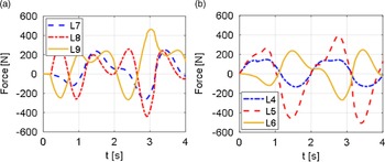
The driving force of the electric cylinder is deduced through simulation and the displacement of the electric cylinder is calculated. And the following results can be obtained, such as the driving diagram and displacement diagram of the electric cylinder of the front and rear feet of the robot shown in Fig. 11(a) and (b). Since the left and right sides of the robot structure are symmetrical, only the driving force and displacement results of the electric cylinder on the front and rear feet are displayed.
Driving force of the front and rear foot cylinders: (a) Driving force of the unilateral electric cylinder for the front foot. (b) Driving force of the unilateral electric cylinder for the rear foot.

According to the basic parameters of the electric cylinder, the maximum thrust is 1000N. After the results of dynamic simulation, it can be seen that the peak driving force is 500N-600N, which does not exceed the maximum thrust of the electric cylinder. The final driving force of the model can be transferred to the driving equipment.
5. Experiment
5.1. Simulation experiment
In this section, in order to verify the validity of kinematics optimization method based on PSO-CPG algorithm and the correctness of the dynamic model of this system, simulation experiments of parallel mobile rescue robot are carried out. At the same time, for reasons of better comparison and highlighting the superiority of this method, simulation results optimized through GA-CPG methods without involving dynamic model are also demonstrated.
5.1.1. Simulation based on GA-CPG algorithm
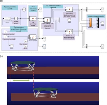
The co-simulation of ADAMS and Simulink is employed here, which can simultaneously control and simulate the motion of the parallel mobile rescue robot. Firstly, the model built in SolidWorks is directly imported into ADAMS software, and the ADAMS model can perform motion simulation according to the commands sent by Simulink, as shown in Fig. 12(a). The actions of the robot, such as start, stop, and motion, can be controlled in real time on Simulink’s platform. In the Simulink environment, basic parameters such as robot walking speed, step cycle, step distance, and stride can be adjusted, and real-time feedback data such as speed, displacement, force, etc. can also be read in ADAMS.
Robot motion simulation diagram in ADAMS-Simulink environment: (a) The control diagram in Simulink. (b) The motion simulation in ADAMS.

When the optimized gait has a 2
 $\rm s$
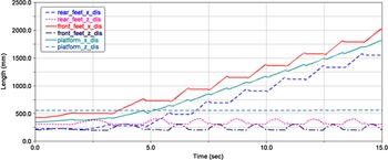
cycle, a 300 mm distance, and a 100 mm stride, the simulated motion in the X direction is shown in Fig. 12, and the data curves are shown in Fig. 13. After measurement, the forward distance in the X direction is 2250 mm. From Fig. 13, before 4
 $\rm s$
, the step distance and stride parameter values of the robot increase proportionally.
The displacements of the robot’s upper platform, front and rear feet.

The simulation results show that the robot moves relatively smoothly in the X direction within 15
 $\rm s$
, and the gait parameters reach the set value after 4
 $\rm s$
. As shown in the figure, the displacement of the upper platform in the Z direction is almost zero, and it only fluctuates slightly when the robot starts with the set step distance and stride. Moreover, as the optimization method has not yet involved a dynamic model, there will be an impact force when the robot’s feet touch the ground, causing the robot to experience slight bumps. There is an initial difference in the selection of measurement points between the front and rear feet. After the gait parameters reach the set values, the X and Z displacements of the feet are very close to the design displacement curve. In the X direction, the front and rear feet exhibit periodic and uniform motion, while in the Z direction, they move according to the CPG set pattern.
5.1.2. simulation based on PSO-CPG algorithm
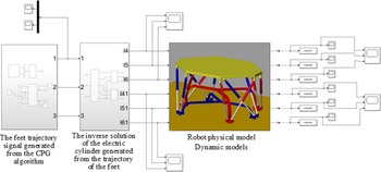
The SimMechanics application platform in Matlab software can provide convenient, reliable, intuitive, and efficient modeling and analysis methods for multi-body system dynamics and control. In this paper, a multi-body dynamic model and motion control model are established and simulated by using SimMechanics for a parallel mobile robot, which complete the verification and motion simulation of the dynamic equation of the robot system. Due to SimMechanics being built into Simulink applications, all multi-body system dynamics and motion control based on PSO-CPG are completed by dividing modules in Simulink. Firstly, a visualized physical model of the robot is obtained in SimMechanics and connected through constraints to form a dynamic model of the overall multi-body system. Then, in Simulink environment, the robot’s motion control is carried out employing the control method based on PSO-CPG algorithm and the dynamic model. Finally, all motion control modules are encapsulated to obtain the overall robot control system as shown in Fig. 14.
The overall motion control system of the robot.

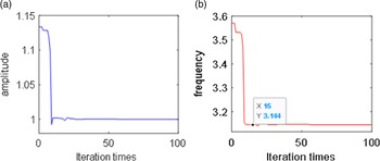
Through the simulation experiment, the optimal values of amplitude and frequency in the Hopf model optimized by PSO algorithm can be obtained, as shown in the following Fig. 15 and Table II.
Optimization results of the PSO: (a) optimal results of the amplitude and (b) optimal result of the frequency.

Parameter value after optimization.

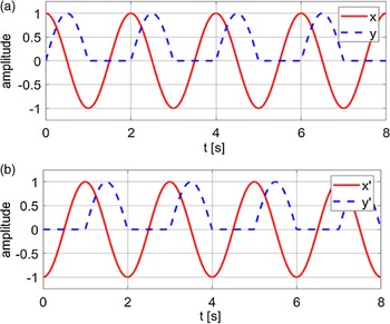
By substituting the optimized parameters back into the CPG model, the signal results can be obtained, as shown in Fig. 16. It can be seen from the figure that the output signal of the optimized Hopf model conforms to the set robot motion mode.
Optimized Hopf signal: (a) the optimized front foot Hopf signal and (b) the optimized rear foot Hopf signal (In the figure, x and y represent the displacement control signal in the Z direction of the robot’s foot end; x’ and y’ represent the displacement control signal in the X direction of the robot’s foot end).

After the optimized control signal is transmitted to the CPG model, the inverse kinematics solution is performed to obtain the displacement curve of the front and rear foot electric cylinders as shown in Fig. 17. It can be seen from the figure that the displacement variation value of the front and rear foot cylinders of the robot can reach the maximum value at the same time, which improves the displacement variation of the electric cylinder. The solution to the problem of displacement hysteresis and sudden change of the electric cylinder enables the platform on the parallel mobile rescue robot to move stably and horizontally.
Displacement curve of the electric cylinder after PSO-CPG optimization. (a) Displacement curve of the front leg electric cylinder and (b) displacement curve of the rear leg electric cylinder.

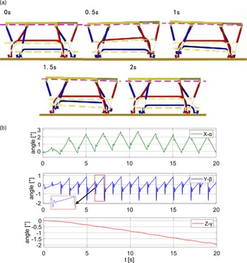
After applying the optimized Hopf model, the platform on the robot can move smoothly, as shown in Fig. 18(a). The swing amplitude of the upper platform is relatively small, as shown in Fig. 18(b), which the swing amplitude around X, Y, and Z axes is between
 $-2^{\circ }\sim 3^{\circ }$
.
Robot motion process of the optimized Hopf model. (a) Motion process of the robot and (b) Euler angle change of the robot.

Moreover, the simulation results based on PSO-CPG method and the dynamic model are significantly superior to the GA-CPG method, as it eliminates the fluctuation during the transition phase of the startup and motion cycle, as well as the contact impact with the ground. Thus, the robot can achieve excellent motion performance.
5.2. Real machine experiment
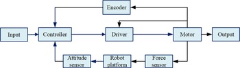
In this section, a physical experimental study on parallel mobile robots is conducted based on a self-developed prototype. Taking PLC as the core controller, TwinCAT3 as the software environment, and using EtherCAT bus technology, invariably horizontal control experiment of the robot is completed to verify the reliability of the dynamic model of the parallel mobile robot and the kinematics optimization method based on PSO-CPG algorithm. The rescue robot is supported by 12 motion electric cylinders to achieve the entire motion effect through the design of leg control system and multi-axis control strategy, the block diagram of the robot control system is shown in Fig. 19.
The block diagram of the robot control system.

The robot system consists of three closed-loop layers. The first layer, which is the innermost layer, is achieved by a current closed-loop between the driver and the motor. This part requires initial parameter tuning of the driver based on the load situation; The second layer is a position (or speed) closed-loop composed of position signals (speed) fed back by motor encoders or electric cylinder linear displacement rulers; The third layer is fed back by the attitude sensor of the robot’s upper platform to achieve closed-loop position and attitude control, ensuring invariably horizontal motion of the robot’s upper platform. The priority relationships of the three closed-loop systems are in descending order: current loop, speed/position loop, and attitude angle loop. The three closed-loop systems cooperate with each other to comprehensively ensure the safety and stability of the robot’s walking process.
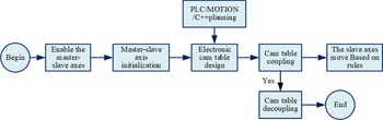
The basic principle of the leg control system is shown in Fig. 20, and the controller is responsible for communicating with all actuators and sensors. The controller communicates with the driver through the EtherCAT bus, including data feedback from various motor encoders and grating rulers, and reading of switch signals from the digital input module. Each driver outputs three UVW motor control signals and inputs one motor coding signal to achieve servo drive of each group of driving legs.
The control flowchart of electric cylinders.

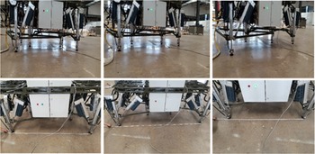
The following is the experiment of the robot prototype based on the above theoretical research. Figure 21 is the robot walking experiment scene after using the PSO-CPG algorithm. This experiment is carried out in a flat environment. The experimental results show that the platform of the robot can move at a constant level, which ensures the stability and safety of the robot.
Test environment of the parallel mobile rescue robot.

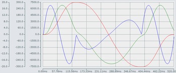
Figure 22 is the change curve of motor parameters on the robot. The red curve is the rotation angle curve of the motor, the green curve is the rotation speed curve of the motor, and the blue curve is the rotation acceleration curve of the motor. From the curve changes in Fig. 19, it can be found that there is no major abnormality in the motor of the robot during movement. The parameters of the motor change smoothly. It also shows that the proposed algorithm and the established dynamic model are feasible and the motion of the robot is stable and safe.
Parameter variation curve of the motor on the robot. (a) The red curve represents the rotational angle of the motor, (b) the green curve represents the rotational speed of the motor, and (c) the blue curve represents the rotational acceleration of the motor.

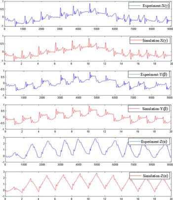
Figure 23 is a graph of the actual Euler angle change of the platform on the robot. The angle change curve of the upper loading platform swinging around the X, Y, and Z axes during robot movement are illustrated in detail in the figure. The odd-numbered rows (blue) represent the measured change angle in the experiment, and the even rows (red) represent the simulated measured change angle. The swing range of the platform on the robot is relatively small in the actual movement process and basically stable between −2
 $^{\circ }$
and 3
 $^{\circ }$
. The experimental results are basically consistent with the simulation results, indicating that the upper platform is basically in constant motion when the parallel mobile robot moves, and indicating the rationality of the dynamic model and the effectiveness of the kinematics optimization method based on PSO-CPG algorithm.
Euler angle variation curve of upper bearing platform.

6. Conclusion
The kinematics optimization method based on the PSO-CPG algorithm proposed in this paper effectively solves the hysteresis problem of the displacement change of each electric cylinder of the parallel mobile rescue robot. The dynamic model of the robot also provides the basis of force feedback for the invariably horizontal control system. Through experimental verification, the proposed kinematics optimization method and dynamic model ensure that the platform on the rescue robot moves at the invariably horizontal state, which also improves the safety.
It is worth noticing that there remains a lot of work to be done in the future. We will continue to conduct theoretical and experimental research and apply this method to uneven surfaces such as slopes and steps. At same time, in order to improve the overall stability of robot motion, the invariably horizontal control strategies will be improved to further adapt to various road surfaces, as well as mitigate the impact of contact with the ground. Next, attention should be paid to the obstacle avoidance and positioning navigation performance of robot, further improving its mobility.
Author contributions
Wenchang Zhang and Hang Wu conceived and designed the study; Xuefei Liu and Wei Chen presented the method and performed the simulation modeling and experiments; Xuefei Liu and Wenchang Zhang wrote the manuscript; Hao Cheng participated in the experiment of the test prototype, during the revision of the paper according to the reviewers’ comments; Wei Chen and Yutao Men embellished the paper and added the required contents.
Financial support
This work was supported in part by the Foundation of Tianjin Science and Technology Plan under Grant 19YFZCSN01150, in part by the Foundation of Science and Technology Innovation 20-163-12-ZT-006-002-09, and in part by the Academy of Sciences Equipment Scientific Research JK20191A010024.
Competing interests
The authors declare no competing interests.