


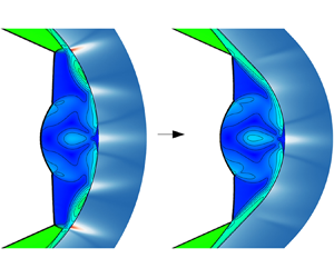

1. Introduction
Heating caused by shock interaction is a critical issue in the design of high-speed vehicles, as it can create extremely localized high-pressure regions with intense heat fluxes on the surface (Wieting & Holden Reference Wieting and Holden1989). One prominent example of this effect was the failure of the X-15-2 flight experiment in 1967, which resulted from an unexpected shock interaction that generated high heating loads and burned the engine mount (Watts Reference Watts1968). Given the widespread practical applications, comprehending and managing these shock interactions are crucial for designing high-speed vehicles. To comprehend the intricate physical mechanisms involved, Edney (Reference Edney1968a) established the first classification of shock interactions into six types, denoted as types I–VI. Based on this classification scheme, Edney (Reference Edney1968b) identified the generation mechanism of heating peaks caused by an oblique shock impinging on a bow shock (BS), which involves the shock wave–boundary layer interaction, the attachment of a shear layer and the impingement of a supersonic jet. Subsequently, Hains & Keyes (Reference Hains and Keyes1972) and Keyes & Hains (Reference Keyes and Hains1973) conducted systematic studies of the aerodynamic pressure/heating distributions on the wall under different types of shock interaction, using both experimental and theoretical analysis. The results showed that the most severe wall heating peaks occurred in types III and IV shock interactions, reaching up to 17 times and 14 times the heating at the undisturbed stagnation point, respectively. Following that, Grasso et al. (Reference Grasso, Purpura, Chanetz and Delery2003) confirmed that in type IV shock interaction, the wall heat flux is most severe when a supersonic jet impinges perpendicularly on the wall, through experiments. Building upon these foundations, researchers have conducted extensive studies over the past several decades into shock interactions induced by typical configurations, such as a double wedge (Ben-dor et al. Reference Ben-dor, Vasilev, Elperin and Zenovich2003; Durna, Barada & Celik Reference Durna, Barada and Celik2016), a double cone (Druguet, Candler & Nompelts Reference Druguet, Candler and Nompelts2005; Tumuklu, Levin & Theofilis Reference Tumuklu, Levin and Theofilis2018), a swept compression ramp (Vanstone et al. Reference Vanstone, Musta, Seckin and Clemens2018) and a curved wedge (Cheng et al. Reference Cheng, Yang, Zheng, Shi, Zhu and You2022; Zhang et al. Reference Zhang, Xu, Shi, Zhu and You2023b). These investigations have greatly enriched our comprehension of shock interactions and the accompanying thermal characteristics. Despite this, the evolving contours of hypersonic aircraft have given rise to new aerodynamic components, leading to increasingly complex and diverse heat generation mechanisms, which present fresh challenges for researchers.
In recent years, the three-dimensional inward-turning inlet has gained significant attention in aerospace due to its advantages, such as powerful capture ability, high compression efficiency and lower pressure losses (You Reference You2011; Gollan & Smart Reference Gollan and Smart2013; Bisek Reference Bisek2016). Concurrently, shock interactions on the engine inlet cowl of inward-turning inlets have attracted increasing interest as they have been found to result in extremely high heating loads (Xiao et al. Reference Xiao, Li, Zhang, Zhu and Yang2018; Li et al. Reference Li, Zhang, Wang and Yang2019; Zhang et al. Reference Zhang, Li, Li and Yang2019). Since the lip of the inward-turning inlet is formed at the intersection of the inlet capture curve and the shock surface in the internal basic flow field, it usually takes on a V-shape, as shown in figure 1 (the centre body is set up to prevent the formation of the Mach disk over the centreline Zhang et al. Reference Zhang, Hu, Da, Shi, Zhu and You2024a). When the leading edges are blunted to meet aerothermal protection requirements, the shocks are no longer attached to the body, resulting in a series of complex shock interactions and high aerodynamic thermal loads. It has been pointed out that under high-Mach-number conditions, the local heating may reach up to 24 times the undisturbed stagnation point level, which is even more severe than Edney's type IV shock interaction. To make matters worse, providing thermal protection for the V-shaped cowl is more challenging since simply increasing the bluntness of the leading edge does not have a positive impact (Xiao et al. Reference Xiao, Li, Zhang, Zhu and Yang2018).
V-shaped lip on inward-turning inlets.

To investigate the flow behaviour and heat flux generation mechanisms on a V-shaped cowl, Xiao et al. (Reference Xiao, Li, Zhang, Zhu and Yang2018) first proposed a simplified model of the lips, named a V-shaped blunt leading edge (VBLE), which is composed of a crotch and two swept straight branches. Through performing experiments and numerical simulations, they found that the shock interaction configurations on VBLEs can be classified into three distinct types: regular reflection (RR), Mach reflection (MR) and regular reflection from the same family (sRR), depending on the free stream and geometric parameters. Using this classification, they identified several causes of heating peaks on VBLEs, including the direct impact of supersonic flow on the surface, shock wave–boundary layer interactions, shear layer reattachment and the impingement of supersonic jets from opposite sides. By considering various mechanisms of heat flux generation, Li et al. (Reference Li, Zhang, Wang and Yang2019) established correlations between the heating and pressure peaks for VBLEs using simulation data. Meanwhile, a series of research results have shown that the pressure/heating loads on VBLEs are sensitive to the interaction configurations and that the sRR structure holds great potential in reducing wall heat flux (Wang et al. Reference Wang, Li, Zhang and Yang2020; Wang, Li & Yang Reference Wang, Li and Yang2021; Zhang, Wang & Li Reference Zhang, Wang and Li2022). Considering these factors, Zhang, Li & Yang (Reference Zhang, Li and Yang2021) established criteria for transition between different interaction types through a combination of shock tunnel experiments, numerical simulations and theoretical analyses, to inform the design of the VBLE. However, due to the subsonic region downstream of the Mach stem, the critical parameter determining the transition boundary, i.e. the position of the triple point in the primary MR configuration, cannot be theoretically resolved and can only be determined through numerical simulations. The issue persisted until Zhang et al. (Reference Zhang, Cheng, Shi, Zhu and You2023a) introduced a simplified continuity method, which enables the theoretical resolution of the triple point location and transition boundary. Later on, they further extended the method to VBLEs that feature variable cross-sections and crotches, significantly expanding the potential applications of this theoretical approach (Zhang et al. Reference Zhang, Zhang, Rao, Shi, Zhu and You2024b).
The purpose of investigating the flow mechanisms is to develop effective strategies for reducing heat flux. Currently, flow control methods aimed at reducing heat flux can be broadly classified into passive methods, such as aerospikes (Yadav, Velidi & Guven Reference Yadav, Velidi and Guven2014; Narayana & Selvaraj Reference Narayana and Selvaraj2020) and forward-facing cavities (Yuceil & Dolling Reference Yuceil and Dolling1995; Engblom et al. Reference Engblom, Goldstein, Ladoon and Schneider1997); and active methods, such as opposing jets (Warren Reference Warren1960; Finley Reference Finley1966; Li et al. Reference Li, Wang, Huang and Liu2016) and energy depositions (Hong et al. Reference Hong, Wang, Li and Ye2014; Sudarshan et al. Reference Sudarshan, Deep, Jayaram, Jagadeesh and Saravanan2020). Recently, some classical flow control methods have been applied to the VBLE for heat flux reduction. Liu et al. (Reference Liu, Yan, Kang, Jiang and Sun2023) developed a scheme using opposing jets to reduce heat flux on the VBLE and found that the local heating peak on the wall surface can be reduced by over 45 % with this approach. To guide the optimization of this scheme, they also conducted an uncertainty quantification analysis of free stream and jet flow parameters. Meanwhile, Kang et al. (Reference Kang, Yan, Liu, Wang and Jiang2023) introduced a shock control bump to address the issue of local heating peaks caused by the shock wave–boundary layer interaction on VBLEs. Under a high free stream Mach number, the shock control bump effectively suppressed the separation of the boundary layer and reduced the local heat flux peak by 66 %. Nevertheless, setting a shock control bump can lead to an elevation of the heating level at the stagnation point, particularly at lower free stream Mach numbers (Li et al. Reference Li, Yan, Kang, Liu and Jiang2023). To reduce the heat flux caused by the impingement of supersonic jets from opposite sides, Li et al. (Reference Li, Yan, Kang, Liu and Jiang2023) introduced a stagnation bulge, which changed the frontal collision of the two supersonic jets into an oblique collision and significantly reduced the collision intensity. In a subsequent study, Li et al. (Reference Li, Jiang, Kang, Tong and Yan2024) further proposed a combination scheme of the stagnation bulge with a secondary recirculation jet, resulting in the ability to reduce the heat flux peak by approximately 43 %. Although some progress has been made in the research of heat flux reduction schemes applicable to the VBLEs, there is a requirement for more exploratory investigations in future studies.
This paper is devoted to exploring the mechanisms of pressure and heating generations on VBLEs and propose an effective strategy for heating reduction. A shock-controllable design approach, enabling the inverse design of VBLEs with pre-determined shock configurations, is developed based on the simplified continuity method. The models designed with the approach achieved significant reductions in heat flux peaks, revealing the relationship between the shock configurations and pressure/heating characteristics. The rest of this paper is arranged as follows. Section 2 presents the VBLE model and its flow behaviour in hypersonic flow, including the shock configurations, and the pressure and heat flux distributions. In § 3, the shock-controllable design approach is developed for the VBLE, preceded by an introduction to the simplified continuity method. Section 4 validates the effectiveness of the design approach through numerical simulations and evaluates the aerothermal performance of the VBLE models designed based on different shock configurations. Section 5 outlines the conclusions drawn from this study. The computational model and numerical methods are provided in the Appendix.
2. Geometry of the VBLEs and the shock configurations
For clarity, we first present the geometry of the VBLE and the shock interaction configurations that occur on it in this section. Figure 2(a) depicts the VBLE model used in this study, which is symmetric about the  $x$–
 $y$ plane and the
 $x$–
 $z$ plane, with the origin of the coordinate system fixed at the centre of the crotch. The axes
 $x$,
 $y$,
 $z$ and
 $\varphi$ correspond to the directions of the free stream, transverse, spanwise and circumferential, respectively. As schematically illustrated in figure 2(a), the simplified model is characterized by a crotch radius
 $R$, a leading-edge radius
 $r$, a half-span angle
 $\beta$ and a straight branch length
 $L$. In this work, the parameters
 $R/r = 3.25$ and
 $\beta = 24^\circ$ were selected for the baseline case since the VBLE with these settings has been the focus of much attention in previous research (Wang et al. Reference Wang, Li, Zhang and Yang2020, Reference Wang, Li and Yang2021; Zhang et al. Reference Zhang, Wang and Li2022; Kang et al. Reference Kang, Yan, Liu, Wang and Jiang2023; Li et al. Reference Li, Yan, Kang, Liu and Jiang2023, Reference Li, Jiang, Kang, Tong and Yan2024; Liu et al. Reference Liu, Yan, Kang, Jiang and Sun2023). For clarity, the detailed values of the geometric parameters are presented in table 1. The length of the straight branch is prescribed as
 $L = 30r$.
VBLE model used in this study and the overall flow pattern: (a) schematic diagram of the simplified VBLE; (b) an overview of flow features in the  $x$–
 $z$ symmetry plane for the baseline VBLE under a free stream Mach number
 $M_0$ of 8.

Geometric parameters of the baseline VBLE.

To demonstrate the shock interactions that occurred on VBLEs and the resulting severe pressure/heating loads, a numerical simulation is conducted with the baseline case. As the peak heat flux is typically observed on the centreline of the model ( $y = 0$), the subsequent analysis will concentrate on the
 $x$–
 $z$ symmetry plane. The numerical approach used throughout this paper is described in detail in the Appendix, including a grid independence analysis to demonstrate that the grid set-up is sufficient to achieve the goals of the simulations. Figure 2(b) displays the overall flow features of the baseline VBLE in a hypersonic free stream with a Mach number
 $M_0$ of 8. The straight branches of the VBLE are essentially two swept cylinders, with a sweep angle equivalent to the half-span angle
 $\beta$ (Zhang et al. Reference Zhang, Li and Yang2021). As a result of the bluntness, two detached shock waves (DSs) are generated along the straight branches when the free stream velocity component perpendicular to the branches is supersonic. As the DSs progress downstream, they gradually become parallel to the straight branches with a constant standoff distance
 $l$ from the wall. At this point, we can regard the flow perpendicular to the straight branches as a two-dimensional supersonic flow around a cylinder, as shown in the A–A cross-section. In the
 $x$–
 $z$ symmetry plane, the fully developed DS can be approximated as an oblique shock with a shock angle of
 $\beta$. Within this paper, the straight branch is of sufficient length to ensure that the DS is fully developed before it reaches the crotch.
Further downstream, the shock configurations start to exhibit complexity when the DS reaches the crotch area. Figure 3 illustrates the flow structure in the crotch region, with the wall pressure ( $p$) and heat flux (
 $q$) distributions provided. The pressure and heat flux are normalized by the pressure
 $p_o$ and heat flux
 $q_o$ at the stagnation point of a cylinder with identical radius
 $r$ and free stream conditions, respectively. The value of
 $p_o$ is equivalent to the total pressure behind a normal shock (i.e. the Pitot pressure) and
 $q_o$ is calculated by the Fay–Riddell theory (Fay & Riddell Reference Fay and Riddell1958). In figure 3(a), the numerical schlieren is portrayed in the upper half, while the Mach number contours are depicted in the lower half. The wall is coloured with the heat flux contours. It is shown that the DSs originating from the two straight branches interact with each other in front of the crotch, leading to the formation of a large-scaled Mach stem (MS). As a result, this interaction configuration is referred to as the primary MR. Due to the specific stagnation and accumulation effects of the crotch, a large counter-rotating vortex pair (CVP) is formed behind the MS, causing the MS to exhibit an arched configuration in the centre.
Shock configuration along with the normalized wall pressure ( $p$) and heat flux (
 $q$) in the crotch area: (a) numerical schlieren, Mach number contours and wall heat flux contours; (b) a detailed view of the secondary shock interaction area downstream of the triple point; (c) the pressure and heat flux distributions along the centreline (
 $y = 0$).

Along with the MS, the primary MR also produces a triple point T, a transmitted shock wave (TS) and a shear layer (SL) at the intersection of the DS and the MS. Additionally, the inwardly curved wall initiates a sequence of compression waves, which converge to produce a curved shock wave (CS) behind the DS. Downstream of the triple point T, a secondary shock interaction occurs between TS and CS near the wall at point  ${\rm IP}_2$. This region is further magnified in figure 3(b), where the red lines denote sonic lines. The SL almost coincides with the sonic line that passes through the triple point, as it divides the supersonic jet located behind the TS from the subsonic flow that follows the MS. As the secondary transmitted shock
 ${\rm TS}'$ impinges the wall surface, it causes a shock wave–boundary layer interaction that leads to a separation bubble. At the reattachment point, the wall surface experiences a sharp rise in pressure and heat flux that forms the outermost peaks (labelled as OP). The pressure and heat flux distribution along the centreline, as displayed in figure 3(c), demonstrate that the outermost heating peaks can reach up to nearly 8.7 times the undisturbed stagnation value
 $q_o$, while the peak pressure is approximately 6.6 times the Pitot pressure
 $p_o$.
The flow passing through the shock wave/boundary layer region is still supersonic and travels further downstream surrounded by the shear layer SL. During the downstream motion, the inner pressure/heating peaks (labelled as IP) are produced by the supersonic jet impacting the wall surface. The supersonic jets on the opposite sides ultimately converge at the stagnation point O, thus giving rise to the formation of a central peak (labelled as CP). With the inner and central heating peaks being approximately 3.8 times higher than  $q_o$, the heating loads experienced at the outermost points are the most severe. Considering the high correlation between the heating generation and the shock interaction, it is theoretically feasible to fundamentally eliminate the outmost heating peaks by appropriately designing the shock configuration.
3. Shock-controllable design approach for VBLEs
The shock-controllable design approach for the VBLE is constructed based on the simplified continuity method, which was initially derived by Moeckel (Reference Moeckel1949) to forecast the form and location of DSs ahead of plane or axially symmetrical bodies. This method was later extended into a three-dimensional form by Zhang et al. (Reference Zhang, Cheng, Shi, Zhu and You2023a) for predicting the shock configurations on VBLEs. In this section, the simplified continuity method is introduced before the shock-controllable design approach is developed. The nomenclature follows that of Zhang et al. (Reference Zhang, Cheng, Shi, Zhu and You2023a).
3.1. Introduction to the simplified continuity method
In our previous research (Zhang et al. Reference Zhang, Cheng, Shi, Zhu and You2023a), a theoretical model has been established for describing the flow pattern on VBLEs based on the simply formed continuity equation, which is a prerequisite for achieving controllable shock configurations. As shown in figure 4, the simplified continuity method was originally proposed by Moeckel (Reference Moeckel1949) to predict the form and location of the detached shock DS ahead of two-dimensional blunt bodies. The solid black line in the figure represents the contour of the blunt body, while the solid red line represents the DS. The Cartesian coordinate system lies in the flow plane, with the  $x$-axis parallel to the free stream. The locations where the body and the DS intersect the
 $x$-axis are the respective leading edges, identified as points O and D. Point O is positioned at the coordinate origin, and the distance between these two points is referred to as the standoff distance
 $l$. At the foremost point D, the DS is a normal shock, and as it progresses downstream, it approaches the Mach wave asymptotically. Thus, it can be observed from the figure that the Mach line of the free stream, denoted by the red dashed line, acts as the asymptote of DS. The asymptote is inclined at the Mach angle
 $\alpha = \arcsin {(1/M_0)}$ and intersects the
 $x$-axis at point A. Given these features, the method hypothesizes the hyperbolicity of DS, which can be mathematically formulated as
 \begin{equation} y = k\sqrt {{{({x - {x_A}})}^2} - {{({{x_D} - {x_A}})}^2}}, \end{equation}
where  $k$ is the tangent of angle
 $\alpha$. Since the DS goes through the transition from a normal shock to a Mach wave, there is necessarily a sonic point S on it where the flow behind it is sonic. With the geometric equation (3.1) and classical oblique shock relations, the coordinates of point S and the corresponding flow deflection angle
 $\delta _S$ can be easily derived. Simultaneously, as the flow along the wall experienced the process of accelerating from zero speed at the stagnation point O to supersonic, a sonic point B is also present on the wall surface. The location of point B can be determined with the shock detachment angle
 $\delta _B$ (Busemann Reference Busemann1949). The blue dashed line that connects points B and S is designated as the sonic line. The inclination angle
 $\eta$ of the sonic line is approximated as the average of
 $\delta _S$ and
 $\delta _B$. In the region upstream of the sonic line, the flow behind the shock is subsonic and accelerates isentropically to reach the sound speed before exiting the line. This allows the derivation of the following simplified continuity equation:
 \begin{equation} {A_S} = \sigma {A_0}\frac{{{P_0}}}{{{P_C}}}. \end{equation}
Two-dimensional simplified continuity method for the detached shock (DS) ahead of plane or axially symmetrical bodies (Moeckel Reference Moeckel1949).

In this equation,  $\sigma$ represents the contraction ratio needed for the free stream to decelerate isentropically and achieve sonic velocity. Here,
 $P_0$ is the stagnation pressure of the free stream, whereas
 $P_C$ approximates the average stagnation pressure downstream of the DS. Additionally,
 $A_0$ represents the projected height of the shock DS below point S in the direction of the incoming flow, and
 $A_S$ is the length of the sonic line. These variables are functions of the standoff distance
 $l$ and the incoming flow conditions. By solving (3.2), the position of the DS can be theoretically predicted. Expressions of these variables and derivation details of (3.2) have been given by Moeckel (Reference Moeckel1949).
The two-dimensional simplified continuity method described above has previously been employed to predict the location of the swept DS generated on the straight branches of VBLEs (Zhang et al. Reference Zhang, Cheng, Shi, Zhu and You2023a). Further, by considering the spanwise flow, the method is extended to three-dimensional space to describe the flow structure in the crotch region, as depicted in figure 5. The figure illustrates a quarter of the primary shock configuration ahead of the crotch. The  $x$–
 $y$ and
 $x$–
 $z$ symmetry planes are coloured in light blue. The body contour (BC) of the VBLE is depicted by the grey surface, while the green, re, and purple surfaces around it represent the detached shock wave DS, Mach stem MS and transmitted shock wave TS, respectively. The orange-coloured side surface is parallel to the
 $x$–
 $y$ symmetry plane and intersects the triple point T. The MS is assumed to be linear on the
 $x$–
 $z$ symmetry plane and hyperbolic in the planes parallel to the
 $x$–
 $y$ symmetry plane. Disregarding the CVP-induced distortion of the MS, it is assumed to be linear in the
 $x$–
 $z$ symmetry plane and hyperbolic in planes parallel to the
 $x$–
 $y$ symmetry plane. Consequently, the intersection line DT between the MS and the
 $x$–
 $z$ symmetry plane is straight, and a sonic line
 ${\rm SS}_1$ exists on the MS outside the plane. On the wall surface, the sonic line is represented by
 ${\rm BB}_1$. Therefore, a sound throat ST exists between the wall and the MS, as coloured in blue. The subsonic flow behind the MS, as well as the flow entering from the side surface, will exit through the throat at the sound speed. Assuming that the process is isentropic gives the following three-dimensional continuity relation:
 \begin{equation} {A_{ST}} = \sigma {A_{MS}}\frac{{{P_0}}}{{{P_C}}} + {\sigma _{Side}}{A_{Side}}. \end{equation}
Three-dimensional simplified continuity method for shock configuration in the crotch region of VBLEs (Zhang et al. Reference Zhang, Cheng, Shi, Zhu and You2023a).

Here,  $A_{ST}$,
 $A_{MS}$ and
 $A_{Side}$ denote the projected areas of the sonic throat ST, the Mach stem MS and the side surface in the direction of flow through them. Additionally,
 $\sigma _{Side}$ is the isentropic contraction ratio required for decelerating the flow passing through the side surface to sonic speed. These variables are dependent on the geometric and free stream conditions. Solving (3.3) yields the triple point position
 $d$ (or the MS height
 $H_m$), which determines the primary shock configuration. The detailed derivation of (3.3) and its associated parameters have been presented by Zhang et al. (Reference Zhang, Cheng, Shi, Zhu and You2023a).
3.2. Shock-controllable design approach
The simplified continuity method-based theoretical model establishes an analytical relationship between the geometry of VBLEs and the shock configurations. Once the free stream and geometric conditions have been determined, the shock structures can be solved using the continuity equations (3.2) and (3.3). Similarly, by specifying the shock configuration and incoming flow, the corresponding VBLE geometry can be sketched out. Considering the great potential of the sRR structure in heating reduction (Wang et al. Reference Wang, Li, Zhang and Yang2020, Reference Wang, Li and Yang2021; Zhang et al. Reference Zhang, Wang and Li2022), we can designate the primary shock interaction as an sRR in the design of VBLEs.
Figure 6 presents schematic diagrams of the primary MR and sRR configurations in the  $x$–
 $z$ symmetry plane, along with the corresponding shock polars. The red numbers and curves represent the flow and shock states in the primary MR configuration, while the blue colour represents the state in sRR. The shared state is represented by black. The free stream is denoted as (0), and the subregions behind the DS and CS are indicated by (1) and (2), respectively. Table 2 provides the flow Mach number in each subregion. It should be noted that the two-dimensional shock polars are only used for qualitative analysis due to the complex three-dimensional flow features on VBLEs.
Schematic diagrams of (a) the primary MR and (b) sRR configurations in the  $x$–
 $z$ symmetry plane, along with (c) the corresponding shock polars.

Flow Mach number in each subregion.

The critical difference between the primary MR and sRR structures lies in the relative position of the triple point T and the curved shock CS. As depicted in figure 6(a), for the primary MR, the triple point T is positioned nearer to the upstream side and appears before the intersection of the DS and the CS. Due to the weak strength of the DS, a strong TS is emitted from the triple point, producing a subregion (3) to balance the high pressure in subregion (4) behind the MS. As the TS and CS interact downstream at point IP $_2$, the airflow is recompressed by the secondary transmitted shock TS
 $'$ and curved shock CS
 $'$, with the pressure rising to an extremely high value behind them in subregions (5) and (6). Subsequently, the shock wave–boundary layer interaction between the TS
 $'$ and the wall surface will continue to compress the flow, resulting in a further increase in the pressure. In certain scenarios, when the triple point is close to the downstream, the DS may initially intersect with the CS from the same branch to generate an sRR configuration, as displayed in figure 6(b). At the intersection point IP
 $_3$, the DS and CS converge into a stronger transmitted shock wave, referred to as a curved DS (CDS) (Zhang et al. Reference Zhang, Li and Yang2021). This produces a sequence of expansion waves (EWs) downstream of the CS. As the flow traverses through the EWs from subregion (2
 $'$) to (3
 $'$), the pressure experiences a certain level of decrease. Eventually, the pressure balances out with that of subregion (4
 $')$ located behind the CDS. Since the flow in subregion (4
 $'$) remains supersonic (as listed in table 2), Mach reflection still occurs at the triple point T downstream of the CDS, transforming it into an MS or a concave BS (Zhang et al. Reference Zhang, Zhang, Rao, Shi, Zhu and You2024b). Nevertheless, owing to the strong intensity of the CDS, only a weak transmitted shock TS emerges from the triple point, leading to a slight increase in pressure. When the weak TS impinges on the wall surface, it will not induce the separation of the boundary layer due to the minimal adverse pressure gradient. Consequently, the pressure can be kept at a reduced level in the sRR configuration, as shown by the point representing subregions (5
 $'$) and (6
 $'$) in figure 6(c).
Upon a brief review of figure 6(c), it is evident that the primary MR configuration results in significantly higher pressure when compared with the sRR configuration. As a matter of fact, the gap between the two configurations may be even more pronounced than that depicted in the figure, owing to the presence of the shock wave/boundary layer interaction in the former. Given the high correlation between the pressure and the heat flux (as shown in figure 3c), the MR configuration can result in an exceedingly more severe heating load than sRR.
From the aforementioned analysis, the adjustment of the relative position of the triple point T and the CS is the key to facilitating the transition of the interaction configuration from the primary MR to sRR. Accordingly, the shock-controllable design approach outlined in figure 7 is proposed. This approach involves the inverse design of the crotch sweep path based on predetermined shock configurations. In the figure, the bold line signifies the sweep path, which is aligned with the centreline of the VBLE. The junction of the straight branch and the crotch is denoted as the elbow. The intersection point between the wall-normal line at the elbow and the  $x$-axis is denoted as O
 $'$. The distance between O
 $'$ and the elbow is the radius R of the crotch in the baseline case (figure 2a). Due to the symmetry of the VBLE, the sweep curve is perpendicular to the
 $x$-axis at the stagnation point O. The sweep path of the crotch is divided into three parts: the pure supersonic segment SS (the solid red line), the linear transition segment LtS (the dashed blue line) and the rounded segment RS (the solid blue line). Each part of the sweeping curve is determined by the shock wave of the same colour. Thus, the contour of the curved shock CS and the position of the triple point T can be separately designed. Next, the design methods for different segments will be introduced.
Inverse design method of the crotch sweep path for given shock configurations.

Considering the dependence of the stagnation point O on the shock configuration, the point O $'$ is selected as the origin of the coordinate system. In this scenario, the sweep path of the straight branch can be expressed by the following equation:
 \begin{equation} z ={-} \tan \beta \left( {x - \frac{R}{{\sin \beta }}} \right). \end{equation}
As established in § 2, a fully developed DS can be regarded as an oblique shock parallel to the straight branch with a standoff distance  $l$, which can be calculated using the two-dimensional simplified continuity method. As such, it is appropriate to characterize the DS using the following equation:
 \begin{equation} z ={-} \tan \beta \left( {x + \frac{{l - R}}{{\sin \beta }}} \right). \end{equation}
With the shock angle  $\beta$, the Mach number immediately behind the DS, as well as other flow parameters, can be determined using the oblique shock relations. Assuming a linear decrease from
 $M_{n2}$ behind the DS to 0 at the wall surface along the stagnation line (Sinclair & Cui Reference Sinclair and Cui2017), the distributions of these parameters between the DS and the wall can be theoretically estimated. With these parameters available, once the shape of the curved shock CS is given, the corresponding wall SS can be solved inversely by the method of curved-shock characteristics (Shi et al. Reference Shi, Zhu, You and Zhu2021) since the flow behind the CS is typically pure supersonic. In practical calculations, the CS is discretized into a series of straight shocks. By solving the compatibility relations upstream along the right-running characteristics behind each shock segment, the post-shock flow field is obtained. The pure supersonic segment SS can be identified by the streamline that originates from the elbow. In this paper, the CS is defined as a circular arc, which is characterized by an initial shock angle
 $\theta _w$ and a radius of curvature
 $R_{CS}$,
 \begin{equation} {({x - {x_{O''}}})^2} + {({y - {y_{O ''}}})^2} = R_{CS}^2, \end{equation}
where the coordinates ( $x_{O''}$,
 $y_{O''}$) is the centre of the CS contour,
 \begin{equation} \left.\begin{gathered} {x_{O''}} = R\sin \beta - {R_{CS}}\sin ( {{\theta _w} + \beta }),\\ {y_{O''}} = R\cos \beta - {R_{CS}}\cos ( {{\theta _w} + \beta }). \end{gathered}\right\} \end{equation}
To ensure a smooth transition from the straight branch to the crotch, the initial shock angle  $\theta _w$ is set equal to the Mach angle of the flow on the wall surface. Therefore, under a fixed inflow condition, the intensity of the CS is completely determined by the curvature radius
 $R_{CS}$.
By solving the geometric equations (3.5) and (3.6), the intersection point IP3 of the CS and the DS (or its extended line) can be found. Based on the coordinates of IP $_3$, the triple point can be further specified. In this paper, the horizontal distance
 $d_T$ between T and IP
 $_3$ is defined as the relative position of the triple point. When
 $d_T$ is negative, it implies that the triple point is located upstream of IP
 $_3$, leading to a primary MR configuration. However, if
 $d_T$ is positive, it means that the triple point is located downstream of IP
 $_3$, as is the case for the position of T
 $'$ in the figure. In such a scenario, the CS will intersect with the DS first, giving rise to an sRR structure. To allow for freedom in the triple point position during design, the latter half of the sweep path (the blue part) is divided into a linear transition segment (LtS) and a rounded segment (RS). Since the starting coordinates and deflection angle of the LtS (i.e. the end of the SS) have already been determined, the blue part can be described using one single parameter, such as the radius
 $R_O$ of the RS. With the analytical relationship between the triple point and the geometry provided by the continuity equation (3), once the triple point is determined, the radius
 $R_O$ can be calculated. Combining this with the pure supersonic segment SS that is solved based on the CS provides the entire sweep path.
4. Results and discussion
In this section, the accuracy of the shock-controllable design approach is first demonstrated using several examples. Building upon this, two models with different types of shock interaction configurations are designed to reduce heat flux and their capabilities are evaluated through numerical simulations.
4.1. Verification of the design approach
This subsection presents four VBLE models (cases A–D) designed with pre-determined shock configurations. These models were subjected to numerical simulations to validate the effectiveness of the design approach.
Figure 8 displays the pre-designed shock configurations and the numerical simulation results for cases A and B, with the wall shaded in grey. The black lines are the numerical Mach number contours and the red solid lines represent the pre-designed shock waves. The  $x$- and
 $z$-axes are plotted in the main diagram and the coordinates are normalized using the radius
 $r$ of the cross-section. The secondary interaction region is magnified on the right-hand side, where dashed lines are used to extend some shock waves and better illustrate the locations of key points. The two models are designed under a free stream Mach number
 $M_0$ of 8 with the curvature radius
 $R_{CS}$ of the curved shock CS specified as
 $5r$. For case A (figure 8a), the relative position of the triple point T is set to
 $d_T = -0.16r$, which is situated upstream of the intersection point IP
 $_3$. As a result, a Mach reflection occurs at T before the DS intersects with the CS. According to the three-shock theory of von Neumann (Reference von Neumann1943, Reference von Neumann1945), the position of the transmitted shock TS emitted from the triple point is also determined. The TS intersects the curved shock CS downstream at point IP
 $_2$, resulting in a secondary RR. In some cases, a secondary MR may occur between the TS and the CS, which is difficult to predict theoretically at present due to the three-dimensional effect of the subsonic flow behind the secondary MS. Nevertheless, given the small size-scale of the secondary shock interaction, it is unlikely to have a significant impact on the design of the primary shock configuration (Zhang et al. Reference Zhang, Cheng, Shi, Zhu and You2023a). For case B, figure 8(b) displays an sRR configuration obtained by the DS intersecting with the CS. In this case, the relative position of the pre-determined triple point is
 $d_T = 0.24r$, which is downstream of the IP
 $_3$, as described by the point T
 $'$ shown in the figure. Due to the intersection, the DS does not extend downstream to point T
 $'$, but converges with the CS and forms a stronger shock wave CDS. The CDS produces a Mach reflection at point T, but the resulting transmitted shock TS is almost invisible due to the decrease in the post-CDS Mach number. For the two cases presented in figure 8, the numerical results exhibit excellent agreement with the pre-set shock configurations, highlighting the effectiveness of the shock-controllable design approach employed in this study.
Comparison of the pre-designed shock configurations with numerical simulations under a free stream Mach number  $M_0$ of 8: (a) Case A,
 $R_{CS} = 5r$,
 $d_T = -0.16r$; (b) Case B,
 $R_{CS} = 5r$,
 $d_T = 0.24r$.

In figure 9, the method is validated for a broader range of free stream Mach numbers and shock parameters using Cases C and D. Case C (figure 9a) is designed under a Mach number of 6. The curvature radius  $R_{CS}$ of the CS is
 $6.25r$, and the position of the triple point relative to IP
 $_3$ is
 $-0.39r$. This results in the primary shock configuration of Case C being MR. In the case of Case D (figure 9b), a higher free stream Mach number of 10 is implemented with an
 $R_{CS}$ of
 $4.17r$ and a
 $d_T$ of
 $0.19r$, resulting in an sRR configuration. The strong consistency between the numerical simulations and the design indicates that the shock configurations on the VBLE can be effectively controlled by the proposed method under different free stream Mach numbers.
Comparison of the pre-designed shock configurations with the numerical simulations under different free stream Mach numbers: (a) Case C,  $M_0 =6$,
 $R_{CS} = 6.25r$,
 $d_T = -0.39r$; (b) Case D,
 $M_0 =10$,
 $R_{CS} = 4.17r$,
 $d_T = 0.19r$.

4.2. The sRR case for reducing heating
In this subsection, a VBLE model will be designed to reduce the surface heat flux caused by shock interactions by properly configuring the shock structures. According to the analysis in § 3.2, the sRR configuration has significant potential for reducing the outermost heat flux caused by shock wave–boundary layer interactions. Nevertheless, transitioning from the primary MR configuration to sRR by moving the triple point downstream can result in a decrease in the curvature radius  $R_O$ at the stagnation point O, which is evident from figure 8. This may lead to an increase in the central heating peak at the stagnation point generated by the collision of opposing supersonic jets (Zhang et al. Reference Zhang, Zhang, Rao, Shi, Zhu and You2024b). Therefore, when designing the shock configuration as an sRR, it is advisable to position the triple point closer to IP
 $_3$. Given these considerations, we devised the model shown in figure 10 with
 $R_{CS} = 5r$ and
 $d_T = 0.14r$ under a free stream Mach number
 $M_0$ of 8. The model is referred to as the sRR case in this paper. The geometric details of the sRR case are available in the figure, showing that the curvature radius at the stagnation point decreases to approximately 4.1 mm in comparison to the baseline case of 6.5 mm.
Geometry of the sRR case designed for reduction heating ( $M_0 = 8$,
 $R_{CS} = 5r$,
 $d_T = 0.14r$).

In the rest of this subsection, a series of numerical simulations are conducted to comprehensively evaluate the heat reduction capabilities of the sRR case across various operational scenarios, including the design point (§ 4.2.1), wide-speed range (§ 4.2.2) and sideslip conditions (§ 4.2.3).
4.2.1. Performance at the design point
Figure 11 displays the numerical simulation results of the sRR case operating under the same incoming flow conditions as the baseline case (§ 2). Numerical schlieren and Mach number contours are shown in figure 11(a), where the wall is coloured by heat flux contours. The heat flux and pressure distributions along the centrelines of the sRR and the baseline cases are compared in figure 11(b,c). The heat flux and pressure distributions of the sRR case are represented by the solid black line, while those of the baseline case are shown by the dashed red line. It is observed that an sRR configuration is present, following the design parameters. Owing to this, the outermost pressure and heating peaks of the baseline case are significantly mitigated. Additionally, due to the absence of the pressure jump caused by the secondary shock interactions and the shock wave–boundary layer interaction, the pressure within the supersonic jets is also reduced. This leads to a decrease in the inner pressure and heating peaks that result from supersonic jets impacting the wall. However, in the sRR case, the central heating peak resulting from the collision of the opposing jets is slightly higher than that of the baseline case due to a decrease in the curvature radius  $R_O$ (figure 10). Nevertheless, significant improvements are still demonstrated in the sRR case, with a 50 % decrease in maximum heat flux and a 62 % decrease in maximum pressure. At the outermost points, the local heating peaks are reduced by nearly 80 %.
Shock configuration along with the normalized wall pressure and heat flux of the sRR case at the design point ( $M_0 = 8$): (a) numerical schlieren, Mach number contours and wall heat flux contours; (b) wall heat flux and (c) pressure distributions along the centreline of the sRR case and the baseline case.

In the previous study aimed at reducing the outermost heat flux, it was discovered that the shock control bump and opposing jets could result in the appearance of the heating peak outside the centreline (Kang et al. Reference Kang, Yan, Liu, Wang and Jiang2023; Li et al. Reference Li, Yan, Kang, Liu and Jiang2023). To address these concerns, further exploration of the heat flux across various  $z$-slices is conducted, as depicted in figure 12. As observed, the heat flux demonstrates an overall decreasing trend with an increase in distance from the
 $x$–
 $y$ symmetry plane, indicating that the design method used in this paper does not lead to heating peaks outside the centreline. These findings suggest that by pre-designing the shock interaction configuration as an sRR, a comprehensive reduction of wall heat flux on VBLE can be achieved under specified design conditions.
Wall heat flux distributions across various  $z$-slices of the sRR case.

4.2.2. Wide-speed range performance
For hypersonic vehicles, it is essential to possess the capability to operate across a wide range of speeds, rather than being restricted to ideal design conditions. Hence, investigating the flow features and heat flux distributions across different Mach numbers is crucial for improving the vehicle's performance under varying conditions.
Figure 13 illustrates the flow features of the sRR and baseline cases when the free stream Mach number drops below the design point. In each subfigure, the flow structures are displayed on the left-hand side and the normalized heat flux distributions along the centreline are plotted on the right-hand side. On the left-hand side, the upper and lower halves display the Mach number contours of the sRR and baseline cases, respectively, alongside heat flux contours on the wall. The flow fields near the outermost heating peaks are amplified and reproduced in the form of numerical schlieren to provide a clear visualization of the shock configurations. The red solid lines in the schlieren denote the sonic lines. Since the designed Mach number is 8, the analysis begins with the case where the free stream Mach number is 7, as displayed in figure 13(a). For the sRR case, it is observed that as the incoming Mach number decreases, the shock interaction configuration transitions into the primary MR, as in the baseline case. In both cases, the TS interacts with the CS to produce the secondary transmitted shock TS $'$, which impinges on the wall surface, leading to the generation of the outermost heating peaks. Nevertheless, the intensity of the TS
 $'$ in the sRR case is much weaker, which fails to induce the separation of the boundary layer. As a result, the outermost heating peaks produced in the sRR case are significantly lower than those in the baseline case. Examining the heat flux distributions along the centreline on the right-hand side, it is apparent that the sRR case still achieves a substantial thermal reduction effect under the operating condition of
 $M_0 = 7$. When the Mach number decreases further to 6, the triple points continue to move upstream, and the primary shock configurations of both cases remain in the MR state, as illustrated in figure 13(b). Under this condition, the secondary interaction between the TS and the CS in the baseline case is no longer an RR, but an MR. A secondary Mach stem MS
 $'$ is produced, followed by a subsonic pocket. In both cases, the impingement of the TS
 $'$ on the wall surfaces leads to a boundary layer separation, resulting in the separation bubbles. Despite this, the maximum heat flux in the sRR case remains considerably lower, with a reduction of 35 %, compared with that of the baseline case.
Flow features and wall heat flux distributions of the sRR case and the baseline case under lower free stream Mach numbers. Solid red lines in the schlieren depict the sonic lines. (a)  $M_0 = 7$, (b)
 $M_0 = 6$.

Figure 14 presents the flow features and heat flux distributions of the sRR and baseline cases when the free stream Mach number exceeds the designed value. As the Mach number increases to 9 (figure 14a), the triple point moves downstream compared with the designed state, allowing the sRR case to retain its original sRR configuration, without causing outermost heating peaks. In the case of the baseline model, although the triple point moves downstream, it does not result in a significant alteration of the flow structure since its initial location was too upstream. Therefore, it also remains in its original MR configuration. At the higher Mach number, the impingement of the TS’ in the baseline case only causes a slight thickening of the boundary layer instead of inducing a separation bubble on the wall surface. Nevertheless, the presence of multiple shocks in the secondary interaction area still leads to an incredibly high value of heat flux at the outermost points. Downstream of the outermost heating peaks, both cases exhibit comparable inner heating peaks as a result of supersonic jets impinging on the wall. As the incoming Mach number is increased to 10, figure 14(b) reveals little significant change in the overall shock configurations and heat flux distributions, which remain similar to observations at  $M_0 = 9$. An apparent variation is that in the sRR configuration, both inner and central heating peaks experience an increase compared with the baseline case.
Flow features and wall heat flux distributions of the sRR case and the baseline case under higher free stream Mach numbers. Solid red lines in the schlieren depict the sonic lines. (a)  $M_0 = 9$, (b)
 $M_0 = 10$.

Table 3 summarizes the heat reduction capabilities of the sRR case across various free stream Mach numbers. The results showcase the excellent wide-speed range performance of the VBLE model designed using the proposed shock-controllable design approach. Optimal performance is achieved at the design state. At a free stream Mach number deviation of 1 from the design point, reductions in the overall heat flux (i.e. the maximum heat flux) of up to 46 % and 47 % can be achieved. Even in the case of a deviation of 2 in Mach number, the overall heat flux can still be reduced by 35 % and 33 %, while the local heating peaks at the outermost points are reduced by 73 % when  $M_0 = 10$.
Heating reduction capabilities of the sRR case under various free stream Mach numbers.

4.2.3. Sideslip performance
Considering the cross-winds encountered during actual flight and the necessity of attitude adjustments, the impact of the sideslip angle is also evaluated. The sideslip angle  $\delta _0$ is defined as the angle between the free stream direction and the longitudinal vertical symmetry plane (the
 $x$–
 $y$ symmetry plane in this paper) of the vehicle. Therefore, sideslip typically leads to highly asymmetrical flow structures.
Figure 15 illustrates the flow characteristics and wall heat flux distributions of the baseline case and the sRR case at a sideslip angle of  $\delta _0 = 5^\circ$. The Mach number contours of the baseline case and the sRR case are presented in figures 15(a) and 15(b), respectively, with the wall coloured by heat flux contours. Since the incoming flow has an upward deflection angle, the upper half is referred to as the windward side, whereas the lower half is denoted as the leeward side. At a sideslip angle of
 $5^\circ$, the shock configurations of both cases exhibit obvious asymmetry. Owing to differences in the velocity components of the free stream perpendicular to the straight branches, the standoff distance of the detached shock DS differs between the windward and leeward sides. The DS on the windward side tends to be closer to the straight branch. In the baseline case, the two asymmetrical DSs interact in front of the crotch, leading to the primary MR configurations on both sides. In the sRR case, however, different interaction configurations are produced on each side. On the windward side, the triple point moves upstream and undergoes a transition to the primary MR, while the shock configuration on the leeward side remains in an sRR. The asymmetry of the flowfield is also apparent in the distributions of the heat flux along the centreline, as illustrated in figure 15(c). The heat flux generated on the leeward side is higher than that produced on the windward side, which can be explained by examining the shock polar, as outlined in our previous work (Rao et al. Reference Rao, Zhang, Shi, Zhu and You2024). For the baseline case, the outermost heating peak on the leeward side exceeds the maximum heat flux observed under the no-sideslip condition (figure 3b), reaching as high as 9.1 times the undisturbed stagnation value
 $q_o$. In the sRR case, given that the sRR configuration is retained on the leeward side, no outermost heating peak appears on this side. Although the MR configuration on the windward side triggers an outermost heating peak, the latter exhibits lower magnitudes. Furthermore, due to the different shock configurations on both sides and the specific geometry of the crotch, the CVP located behind the MS undergoes significant distortion. This prevents a frontal collision between the opposing supersonic jets, thereby minimizing the central heating peak. Consequently, at a sideslip angle of
 $\delta _0 = 5^\circ$, the overall heat reduction capacity of the sRR case is even better than the design state, reducing the maximum heat flux by nearly 65 %.
Flow features and wall heat flux distributions of the sRR case and the baseline case at a sideslip angle of  $\delta _0 = 5^\circ$.

As the sideslip angle increases to  $\delta _0 = 9^\circ$, the asymmetry property of the flowfield becomes more pronounced, as illustrated in figure 16. In the baseline case (figure 16a), although the primary shock configurations on both sides remain MRs, there are variations in their secondary interaction patterns. The windward side exhibits an RR-type secondary shock interaction, whereas the interaction on the leeward side transitions to a secondary MR configuration. Compared with the scenarios with no sideslip and a sideslip angle of
 $5^\circ$, the outermost heating peaks on both sides exhibit a decrease. Regarding the sRR case (figure 16b), the primary MR on the windward side persists, with the shock configuration on the leeward side transitioning from sRR to MR, too. This may be attributed to the rapid increase in the standoff distance of the DS on the lee side. As a result of the changes in shock interaction patterns, the sRR case exhibits an increase in the outermost heating peak on the leeward side, reaching 4.5 times that of the reference value
 $q_o$, as depicted in figure 16(c). Despite this condition, the sRR case continues to demonstrate a considerable reduction in wall heating load, with the maximum heat flux decreasing by roughly 46 %. The results suggest that the VBLE model designed in this study exhibits consistent and robust aerothermal performance even under sideslip conditions.
Flow features and wall heat flux distributions of the sRR case and the baseline case at a sideslip angle of  $\delta _0 = 9^\circ$.

4.3. The MR case for reducing heating
Although the sRR configuration can significantly reduce the local heat flux at the outermost region, the increase in heat flux at the stagnation point affects its overall thermal reduction performance. To achieve a balance between the outermost heating peak and the central heating peak, an MR case is designed, as shown in figure 17. The curvature radius  $R_{CS}$ of the CS is consistent with the sRR case, while the triple point is moved upstream to the relative position of
 $d_T = -0.01r$. Correspondingly, the curvature radius
 $R_O$ at the stagnation point O increases from 4.1 to 5.5 mm compared with the sRR case.
Geometry of the MR case designed for reduction heating ( $M_0 = 8$,
 $R_{CS} = 5r$,
 $d_T = -0.01r$).

Figure 18 presents the numerical results of the MR case operating at the design point ( $M_0 = 8$). In figure 18(a), numerical schlieren and Mach number contours are displayed, while heat flux contours are coloured on the wall. The secondary shock interaction area is enlarged in figure 18(b), where the sonic lines are plotted in red. Figure 18(c) compares the heat flux distributions along the centrelines of the MR case, the sRR case and the baseline case. The heat flux and pressure distributions of the MR case are highlighted with a green line. By placing the triple point T upstream before the intersection of the DS and the CS, it is observed that the flow ahead of the crotch exhibits a primary MR configuration. The resulting transmitted shock TS intersects with the CS at IP
 $_2$, producing a secondary transmitted shock TS
 $'$, which impinges on the wall surface, leading to the appearance of the outermost heating peak. Nevertheless, the weak intensity of the TS
 $'$ does not lead to the separation of the boundary layer. As a result, the outermost heating peaks in the MR case are much lower than those in the baseline case and do not exceed the central heating peak. Moreover, it should be pointed out that due to the increase of the radius
 $R_O$ of the rounded segment RS, both the inner and central heating peaks in the MR case are slightly lower than those in the sRR case. Therefore, despite the outermost heating peaks, the MR case demonstrates better overall aerothermal performance than the sRR case, with a maximum heat flux reduced by 54 %.
Shock configuration along with the normalized wall pressure and heat flux of the MR case at the design point ( $M_0 = 8$): (a) numerical schlieren, Mach number contours and wall heat flux contours; (b) a detailed view of the secondary shock interaction area; (c) wall heat flux distributions along the centreline of the MR case, the sRR case and the baseline case. Solid red lines in the schlieren depict the sonic lines.

Figure 19 presents the heat flux distributions of the MR case under undesigned free stream Mach numbers, compared with the sRR case and the baseline case. Figures 19(a) and 19(b) show the results under lower incoming Mach numbers ( $M_0 = 6$ and 7), while figures 19(c) and 19(d) provide the results under higher free stream Mach numbers (
 $M_0 = 9$ and 10). It is observed that as the Mach number decreases, the heating reduction ability of the MR case decreases rapidly because of the sharp rise in outermost heating peaks. At a Mach number of 6 (figure 19a), although the heat flux of the MR case is still lower than that of the baseline case, its thermal reduction effectiveness is markedly inferior to that of the sRR case, which only reduces the heat flux by approximately 15 %. In contrast, the MR case exhibits superior aerothermal performance under higher free stream Mach numbers. As the shock configuration transitions to sRR, the outermost heating peaks gradually disappear. Noticeably lower values for both the inner and central heating peaks are observed in comparison with the sRR case, and this discrepancy becomes increasingly prominent as the Mach number increases. Under the undesigned operating conditions of
 $M_0 = 9$ and 10, the heat reduction efficiency of the MR case can reach 52 % and 45 %, respectively.
Wall heat flux distributions of the MR and the baseline cases under undesigned free stream Mach numbers.

The results presented in this subsection illustrate that the MR case effectively mitigates the increase in the central heating caused by the reduction of the stagnation curvature radius  $R_O$. However, although the central heating level of the MR case is lower than the sRR case, it is still slightly higher than the baseline case. In practical design, the shock controllable design approach can be combined with the stagnation bulge developed by Li et al. (Reference Li, Yan, Kang, Liu and Jiang2023), to further reduce the central heating and improve the aerothermal performance of the VBLEs.
5. Conclusion
This paper focuses on the aero-heating problem caused by shock interactions on the VBLE in hypersonic flow. An in-depth analysis of the pressure/heating peak generation mechanisms is conducted, along with a shock-controllable inverse design method to achieve heating reduction. A baseline VBLE with  $R/r =3.25$ and
 $\beta = 24^\circ$ is numerically simulated under a free stream Mach number
 $M_0$ of 8. The flow field exhibits a primary MR configuration, with accompanying secondary shock–shock interactions and shock wave–boundary layer interactions leading to the outermost heating peak of up to 8.7
 $q_o$. The shock polars reveal a close association between the heating level and the primary shock interaction patterns. Upon the transition of the shock configuration from the primary MR to sRR, the near-wall pressure and surface heat flux can be substantially reduced.
Given the primary shock configuration is determined by the relative position of the triple point T and the CS, a shock-controllable design approach is proposed based on the simplified continuity method. The approach enables the inverse design of the crotch's sweep path by pre-determined shock configurations. Numerical simulations are conducted on the VBLEs designed with different shock parameters and under various inflow conditions. The numerical simulation results exhibit excellent agreement with the given shock configurations.
A VBLE model designed at a free stream Mach number of 8 with an sRR configuration is comprehensively investigated. Under the design conditions, the shock wave–boundary layer interaction is eliminated at the outermost point, with the local heating peak reduced by 80 % compared with the baseline case. Despite a slight increase in the central heating peak caused by the increased wall curvature at the stagnation point, the overall maximum heat flux is reduced by 50 %. The aerothermal characteristics of the sRR case are also evaluated across various free stream Mach numbers and sideslip angles. Under different undesigned conditions, the shock wave–boundary layer interactions are weakened to some extent, resulting in a decrease in heat flux. In the case of a deviation of  ${\pm }2$ in free stream Mach number from the design point, i.e. at
 $M_0 = 6$ and 10, the maximum heat flux can still be reduced by 35 % and 33 %, respectively.
To mitigate the increase of the central heat flux in the sRR case and improve the overall aerothermal performance of the VBLE, an MR case is designed. The simulation results indicate that, while the local heating reduction effect is not as significant as that of the sRR case, the MR case exhibits a higher overall heating reduction rate of up to 54 %. Additionally, the MR case tends to achieve more significant heat reduction effectiveness under higher free stream Mach numbers. In practical design, optimal design parameters can be selected according to particular flight requirements.
Funding
We would like to acknowledge the support of the National Natural Science Foundation of China (NSFC, grant numbers U20A2069, 12302389, 123B2037 and 12372295).
Declaration of interests
The authors report no conflict of interest.
Appendix. Numerical methods and grid resolution analysis
Numerical simulations are employed in this paper as a reference to verify the design method and evaluate the surface heat flux. The present study conducted numerical simulations via the three-dimensional ideal gas Reynolds-averaged Navier–Stokes equations, which were solved using the finite volume method. Considering the intensified turbulence generation caused by complex shock interactions at the crotch (Xiao et al. Reference Xiao, Li, Zhang, Zhu and Yang2018), a fully turbulent flow was assumed. The one-equation Spalart–Allmaras turbulence model (Spalart & Allmaras Reference Spalart and Allmaras1992) was employed to calculate the turbulence-averaged parameters. The inviscid convection flux was discretized by the Roe approximated Riemann method (Roe Reference Roe1981), and the viscosity terms were discretized through the second-order upwind difference scheme. The specific heat ratio  $\gamma$ was calculated by CHEMKIN format polynomials (Kee et al. Reference Kee, Rupley, Meeks and Miller1996), and the viscosity coefficient was determined by the Sutherland formula.
The schematics of the computational domain and the local structural grid are shown in figure 20. In the simulations performed, we considered three types of boundary conditions: inflow, outflow and solid wall. The inflow boundary was specified using static conditions and free stream Mach numbers ( $p_0 = 1247$ Pa,
 $T_0 = 122$ K,
 $M_0 = 6$–10). At the outflow boundary, the static pressure was prescribed and other flow quantities were extrapolated from the interior flow. The model surface is set as a non-slip, isothermal wall with a fixed temperature of 300 K. The present study employed structured hexahedral grids to discretize the computational domain. Figure 20(b) provides a depiction of the grid near the crotch with notation of
 $\xi$,
 $\zeta$ and
 $\psi$ to represent the grid point counts for the wall-normal, circumferential and spilling directions, respectively. In the current investigation, three-dimensional calculations were conducted without relying on any presumed symmetries. The symmetry planes depicted in the figure were solely added to enhance the display for clarity purposes.
(a) Computational domain and boundary conditions. (b) Grid near the crotch with a quarter of the domain removed.

To verify the grid independence, we conducted a simulation for the baseline case ( $\beta = 24^\circ$,
 $R/r = 3.25$) by using three sets of grid resolutions, namely, coarse, fine and refined grids. Details are provided in table 4. The surface cell thickness for the three grid scales was set to
 $1\times 10^{-6}$,
 $5\times 10^{-7}$ and
 $5\times 10^{-7}$ m, respectively, to ensure accurate simulation of the wall heat flux with
 $y+$ values below 0.2 (Brown Reference Brown2013). In figure 21(a), the surface heat flux distributions on the crotch centreline (
 $y = 0$) obtained from numerical simulations using different grid scales are displayed, along with the experimental measurements conducted by Zhang et al. (Reference Zhang, Li and Yang2021). The results reveal that the simulation results show good convergence as the grid resolution increases. The wall heat flux distributions obtained from fine and refined grids are remarkably analogous and agree well with the experiment results marked by square symbols. In figure 21(b), a comparison is made between numerical and experimental schlieren in the crotch area. It is observed that the shock configurations captured by the simulation also exhibit excellent agreement with the experiment results. Considering the higher resolution of the refined grid, it has been used throughout this paper.
Three sets of grids used in the grid resolution analysis.

Comparisons between the numerical simulations performed in this study and the experimental measurements conducted by Zhang et al. (Reference Zhang, Li and Yang2021). (a) Wall heat flux distributions on the centreline ( $y = 0$) of the crotch with various grid resolutions. (b) Numerical and experimental schlieren.



