I. INTRODUCTION
Instrumented indentation is an efficient and convenient tool for probing mechanical properties of viscoelastic materials, such as polymers and biomaterials. Due to the time-dependent behavior of viscoelastic materials, the widely used Oliver-PharrReference Oliver and Pharr1 method is not suitable here.Reference Ngan and Tang2–Reference Cheng, Cheng and Ni8 Robust methods for characterization of mechanical properties of viscoelastic materials via instrumented indentation are therefore required. Over the past decade, a number of researchersReference Lu, Wang, Ma, Huang and Viswanathan9–Reference Cheng and Yang17 have proposed methods for determining shear creep compliance and shear relaxation modulus from load-depth curves of indentation tests. A common limitation of these methods is that only the data of loading or holding segments, where contact area is nondecreasing, are used. Because they are based on the solution first obtained by Lee and RadokReference Lee and Radok18 as following equations
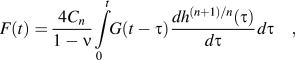
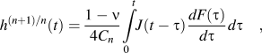
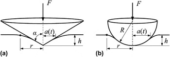
where G(t) and J(t) are the shear relaxation modulus and shear creep compliance, respectively; v is the time-independent Poisson’s ratio; Cn is a constant related to indenter shape, n = 1, C 1 = tan α/π for conical indenter, and α is the included half-angle [see Fig. 1(a)]; n = 2,  for spherical indenter, and R is the radius of spherical indenter [see Fig. 1(b)]. Lee and RadokReference Lee and Radok18 pointed out their solution is valid only for cases that contact area does not decrease with time. Which means Lee-Radok solution is valid during loading and holding, but fails for unloading.
Schematic illustration of indentation; (a) conical indenter and (b) spherical indenter.

Hunter,Reference Hunter19 Graham,Reference Graham20 and TingReference Ting21 addressed the viscoelastic contact problem when contact area has a single maximum. They derived the solution for unloading. When contact area passes through the maximum, the solution is written as
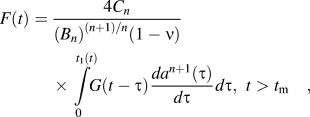
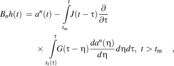
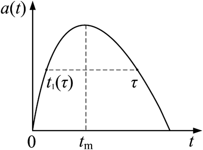
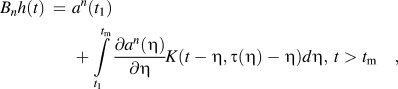
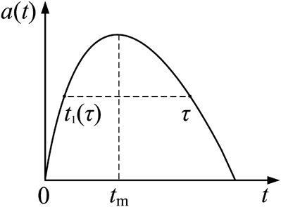
where a(t) is the contact radius at time t; t 1(t) is the instant at which a(t) = a(t 1) (see Fig. 2); t m is the instant at which the contact radius is maximum; Bn is a constant related to indenter shape, for conical indenter, n = 1, B 1 = 2 tan α/π; for spherical indenter, n = 2, B 2 = R. Moreover, GreenwoodReference Greenwood22 recently gave a more convenient form for the variation of the depth during unloading, so Eq. (2b) can be replaced by
Contact radius with a single maximum.
where

Theoretically, when contact radius a(t), load on sample F(t) and depth into sample h(t) are known, shear creep compliance J(t) and shear relaxation modulus G(t) can be determined from unloading segment by using either Eqs. (2a) and (2b), or Eqs. (2a) and (3). However, since shear creep compliance and shear relaxation modulus are coupled in Eq. (2b) and Eq. (3), it is difficult to obtain the explicit formula of shear creep compliance. The determination of shear creep compliance is very complicated in practice. Thus there is a need for finding a more convenient form for determination of shear creep compliance.
In the present work, a large number of finite element (FE) simulations demonstrate that Lee-Radok solution can be regarded as approximately valid for cases of reducing contact area. Base on this finding, three semiempirical methods, which are convenient for determination of shear creep compliance by using the data of both loading and unloading segments, are derived from Eq. (1b). After verification using FE simulations and performance of a typical experiment, these methods have been demonstrated to be reliable within certain tolerance limits.
II. DEMONSTRATION BY NUMERICAL EXPERIMENTS
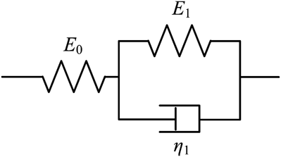
In this section, a large number of FE simulations are implemented to verify the validity of Eq. (1b) when the contact area has a single maximum. Assuming that the shear creep compliance J(t) and loading history F(t) are known, if Eq. (1b) can accurately predict the variation of depth for unloading, then it demonstrates that Eq. (1b) can be applied to cases of decreasing contact area. A three-parameter linear viscoelastic model (see Fig. 3) with time-independent Poisson’s ratio is adopted here, and its shear creep compliance can be expressed as

Three-parameter linear viscoelastic model.
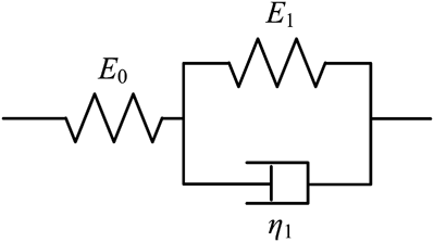
where  indicates the long-term compliance; τ c = η 1/E 1 stands for the retardation time.
A. Prediction of depth
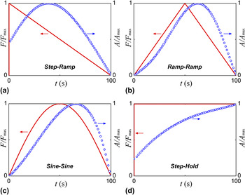
We consider three loading profiles, i.e. Step-Ramp load, Ramp-Ramp load and Sine-Sine load, which will cause the contact area to possess a single maximum [see Fig. 4(a)–4(c)].
Loading profiles (solid lines) and the corresponding normalized contact area (open circles); (a) Step-Ramp load, (b) Ramp-Ramp load, (c) Sine-Sine load and (d) Step-Hold load. The contact area is the fitting result of the calculated contact area from FE simulation.

For Step-Ramp load, a step load is suddenly exerted in indentation and then unloads to zero linearly [See Fig. 4(a)], the indentation load is represented by

where F 0 is the maximum load; V F denotes the unloading rate; and H(t) is the Heaviside unit step function. By inserting Eqs. (5) and (6) into Eq. (1b), the variation of depth can be expressed as
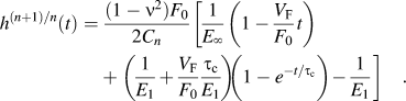
For Ramp-Ramp load, a symmetric triangular load function [See Fig. 4(b)] is used. Let the indentation load be

where V F is the loading or unloading rate and t R is the loading time. By inserting Eqs. (5) and (8) into Eq. (1b), it comes to
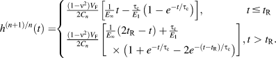
For Sine-Sine load, the load changes with the first half cycle of the sine function as shown in Fig. 4(c), it can be expressed as

where F 0 is the maximum load; and T is the period of a loading cycle. By substituting Eqs. (5) and (10) into Eq. (1b), we get
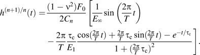
Equations (7), (9) and (11) can be used to predict the variation of depth of both loading and unloading for Step-Ramp load, Ramp-Ramp load and Sine-Sine load, respectively.
B. FE simulations
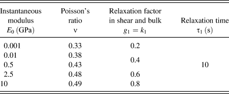
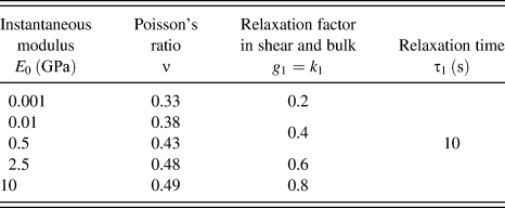
The three-parameter linear viscoelastic model shown in Fig. 3 is implemented in the commercial finite element program ABAQUS.23 We consider a wide range of mechanical properties of polymers that cover the majority of rubber [such as natural rubber (NR), styrene/ butadiene rubber (SBR) and butadiene rubber (BR)] and engineering plastics [such as polymethyl methacrylate (PMMA), polycarbonate (PC) and polypropylene (PP)]. Table I lists the mechanical parameters input into ABAQUS for defining different materials. Since the Poisson’s ratio is time-independent, the relaxation factor in shear should be equal to the relaxation factor in bulk. The instantaneous modulus takes 5 values, the Poisson’s ratio takes 5 values, the relaxation factor takes 4 values and the relaxation time takes one value. So the combination of these parameters leads to 100 (5 × 5 × 4 × 1) different “materials.”
Mechanical parameters input into ABAQUS for defining materials.
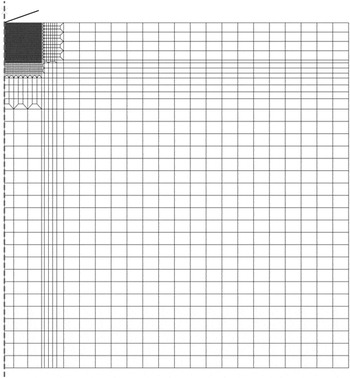
First, tensile tests are simulated to determine the shear creep compliance of the 100 “materials” to verify the material model. Second, we consider a frictionless, rigid conical indenter of included half-angle α = 70.3º indenting isotropic linear viscoelastic solid with four different loading profiles, Step-Ramp load, Ramp-Ramp load, Sine-Sine load and Step-Hold load, as shown in Fig. 4. The Step-Ramp load, Ramp-Ramp load and Sine-Sine load cause the contact area to possess a single maximum, whereas the Step-Hold load leads to a monotonic increasing contact area. For Step-Ramp load, a step load is applied within 0.001 s and then decreased linearly to zero in 100 s. For Ramp-Ramp load, a symmetric triangular load with the same loading and unloading time of 50 s is used. For Sine-Sine load, a load changes with the first half cycle of the sine function  whose period is 200 s. For Step-Hold load, a step load is applied within 0.001 s and then held for 100 s. Since it is an axisymmetric problem, axisymmetric linear quadrilateral elements are adopted. The finite element mesh that consists of a fine-mesh with 2736 elements and a coarse-mesh with 1031 elements is displayed in Fig. 5. The size of the sample is ten times larger than the radius of contact region, so that the sample can be considered as an infinite half-space.
Finite element mesh of indentation.

C. FE results
For conical indenter, n = 1, and  should be replaced with
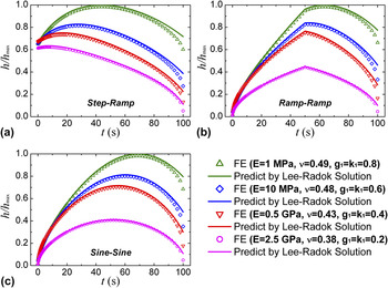
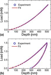
 in Eqs. (7), (9) and (11). The variation of depth predicted by Eq. (7), Eq. (9) or Eq. (11) is compared with the corresponding depth-time curve extracted from the FE simulation. Parts of the results are plotted in Fig. 6, which shows that the predicted depth agrees well with the corresponding FE depth-time curve except for the final section of unloading segment. After viewing all the results of the 100 “materials,” we find out that the relative error is less than 10% for the first 90% of unloading segment, and increases rapidly only in the last 10% of unloading segment. Though the prediction of depth for unloading induces error, the error is in the acceptable range. It demonstrates that within certain tolerance, Lee-Radok solution could be regarded as approximately valid for cases of reducing contact area.
The variation of depth predicted by Lee-Radok solution is compared with that extracted from FE simulation. (a) Step-Ramp load, (b) Ramp-Ramp load and (c) Sine-Sine load.

III. METHODS
As Lee-Radok solution has been demonstrated to be approximately valid for cases of reducing contact area. In this section, three methods which make use of both loading and unloading data to determine shear creep compliance are derived from Eq. (1b). The three methods are named Step-Ramp method, Ramp-Ramp method and Sine-Sine method, respectively, according to the loading profiles [see Fig. 4(a)–4(c)].
A. Methods for determination of shear creep compliance
The Step-Ramp load, Ramp-Ramp load and Sine-Sine load are expressed in Eqs. (6), (8) and (10), respectively. Substituting these equations into Eq. (1b) respectively, after several derivative and integral steps, we get
Step-Ramp method
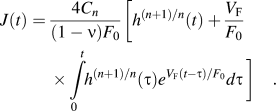
Ramp-Ramp method

Sine-Sine method
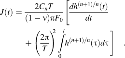
Equations (12), (13) and (14) can be used to compute the shear creep compliance. However, as the measured data is discrete, the computation of the derivative  in Eqs. (13) and (14) will induce error. In order to avoid the computation of
 , a fitting method is adopted to determine the shear creep compliance.
According to the generalized Kelvin model, the shear creep compliance can be written in the form of Prony series
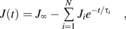
where  is the long-term creep compliance; Ji and τi are compliance constant and retardation time, respectively; N is a positive integer.
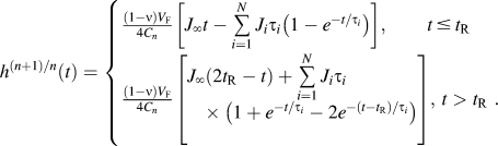
By substituting Eqs. (10) and (15) into Eq. (1b), we obtain the fitting formula for Sine-Sine method
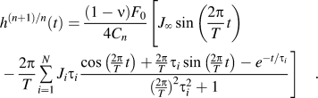
If we fit Eq. (16) or Eq. (17) into the measured depth-time curve using the least squares method, we can find a set of best-fit parameters  ,
 and
 . Then the shear creep compliance can be determined by substituting these parameters back into Eq. (15). In practical applications, Eqs. (13) and (14) are replaced with Eqs. (16) and (17), respectively.
B. Verification of methods by FE simulations
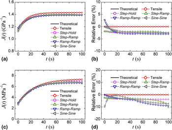
The FE simulations are the same as that implemented in Sec. II. B. For each “material,” the shear creep compliance is determined by uniaxial tensile test and indentation tests with Step-Ramp load, Ramp-Ramp load, Sine-Sine load and Step-Hold load. These testing results of each “material” are compared with the theoretical results, which can be computed using Eq. (5). Typical results are displayed in Fig. 7.
Shear creep compliance determined by different methods are compared with the theoretical result. (a) The shear creep compliance and (b) the relative errors of the “material”  ,
 ,
 ,
 ; (c) the shear creep compliance and (d) the relative errors of the “material”
 ,
 ,
 ,
 .

First, the fact that the tensile test result overlaps perfectly with the theoretical result indicates that the material model used in ABAQUS is correct. Second, the results determined by indentation with different loading profiles also coincide with the theoretical result, but with a maximum relative error of 10.3%. After viewing all the results of the 100 “materials,” we find out the maximum relative error is 13.2%. Though the Step-Ramp method, Ramp-Ramp method and Sine-Sine method are not accurate enough for determination of shear creep compliance, they can be used to approximately determine shear creep compliance. If the relative error of 13.2% is acceptable, the three methods can be regarded as reliable. The most important fact is that the three methods can make use of both loading and unloading data to determine shear creep compliance, whereas the prevalent methods cannot do the same.
IV. EXPERIMENTS
The tests are performed at room temperature (24 °C) using the MTS Nano Indenter XP system (MTS Nano Instruments, Oak Ridge, TN) with the Berkovich indenter, which can be modeled as an equivalent cone with an included half-angle of 70.3°. The material used in the test is PMMA (Anheda Plastic Products Co., Ltd., Suzhou, China). The PMMA specimen is annealed at 120 °C for 2 h in the air and is cooled down slowly to room temperature by switching off the power of the temperature chamber. The Ramp load and Ramp-Ramp load are used in the tests. The Ramp load leads to a monotonic increasing contact area, whereas the contact area of Ramp-Ramp load has a single maximum. For Ramp load, the load increases linearly to the maximum load (1.5 mN) in 100 s. For Ramp-Ramp load, the load increases linearly to the maximum load (1.5 mN) in 50 s and then decreases to zero in 50 s. The peak load is set to be 1.5 mN to make sure the indentation depth is less than 780 nm, because Lu9 pointed out that the indentation depth of 780 nm is the limit of linear viscoelasticity for PMMA by experimental observation. Each indentation test is repeated 5 times and only typical values are presented here.
V. RESULTS AND DISCUSSION
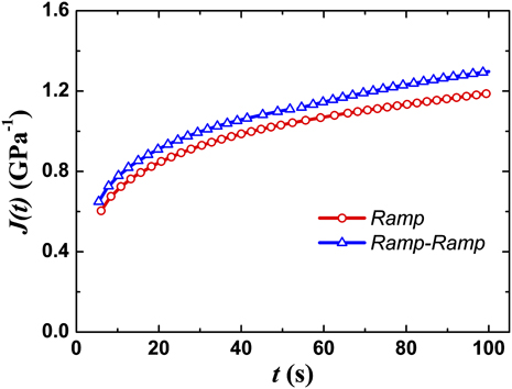
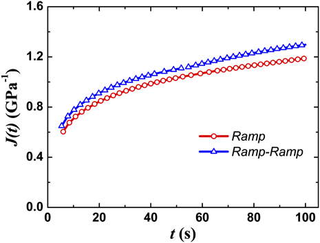
The Ramp method extracts shear creep compliance using the loading data only, but Ramp-Ramp method can determine shear creep compliance using the data of both loading and unloading segments. For Ramp method, Eq. (15) and the upper formula of Eq. (16) are used. The shear creep compliance of PMMA determined by Ramp method and Ramp-Ramp method are plotted together in Fig. 8, so that the results can be compared. As the Ramp method has been proved to be accurate and robust by several researchers,Reference Lu, Wang, Ma, Huang and Viswanathan9, Reference Oyen11 the result of Ramp method can be regarded as the nominal reference value here. The result of Ramp-Ramp method coincides with the result of Ramp method, and the maximum relative error is 12.4%. If 12.4% relative error is in the acceptable range, the reliability of Ramp-Ramp method is acceptable. The shear creep compliance determined by Ramp-Ramp method is discontinuous at the end of loading. And the reason for this discontinuity is that the depth-time curves of loading and unloading segments are fitted respectively with different formulas [see Eq. (16)].
Shear creep compliance of PMMA determined by Ramp method and Ramp-Ramp method.
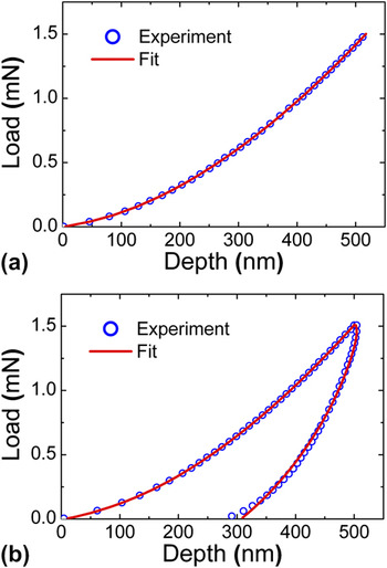
In addition, the shear creep compliance of PMMA determined by Ramp method and Ramp-Ramp method are substituted into Eq. (16) to fit the load-depth curves [see Fig. 9]. It is obvious that the fitting curves overlap well with the experimental curves during loading segment. During unloading segment, the fitting curve also coincides well with the experimental curve except for the last 10% of unloading, as shown in Fig. 9(b). Since the Ramp-Ramp method is derived from Eq. (1b), it indirectly demonstrates that Eq. (1b) is approximately valid for cases of decreasing contact area.
Indentation load-depth curves for (a) Ramp load and (b) Ramp-Ramp load.

VI. CONCLUSIONS
A large number of FE simulations and one typical experiment demonstrate that Eq. (1b) is approximately valid for cases of reducing contact area. It can be used to approximately predict the variation of depth for unloading and determine shear creep compliance using the data of unloading segment. Under the premise that Eq. (1b) is approximately valid for cases of reducing contact area, three semiempirical methods, i.e., Step-Ramp method, Ramp-Ramp method and Sine-Sine method, are proposed for determination of shear creep compliance using the data of both loading and unloading segments. Within certain tolerance, these methods can be regarded as reliable.
ACKNOWLEDGMENTS
The authors would like to thank Prof. Y-T. Cheng for helpful discussion. The support from NSF of China (Project No. 11025212, 10872200, 11172305, 11021262) is also gratefully acknowledged.