1. INTRODUCTION
Several file formats exist for the description of three-dimensional (3-D) information. Most of these file formats are developed for usage in a well-defined application domain. Some of them are designed to contain animation data, some can describe building components, others are used for interactive Web applications, and so forth. As each of these application domains has its own specifications and characteristics, these file formats all have their own way of describing geometry. Each tends to use a partly unique schema with an equally unique syntax and semantics, making it difficult to compare geometric information described in different file formats.
This has an inevitable impact on 3-D design processes in the architecture, engineering, and construction (AEC) domain. A design process in this domain namely involves many parameters stemming from very diverse application domains. As each of these application domains tends to be supported by different specialized software applications, 3-D information describing the design tends to be exchanged continuously between these applications. In this continuous switching back and forth between applications, a designer most often relies on the available conversion processes to translate between the different schemas describing one and the same 3-D model representation.
Many problems arise because of these conversion processes. For example, parts of the information may vanish when converting a file that contains both geometry and product model data to a geometry-only file format. Semantic structures may be lost completely or the geometry may be oversimplified because of the translation process. Meaningful geometric entities, such as spheres, boxes, and so forth, may lose their semantics because they are all converted into a set of triangles or a separately identified mesh object. When a designer thus switches between different applications and file formats, an increasing amount of information gets lost as every conversion process uses the output of the previous conversion. Even when converting back to the original file format, the loss of information is irreversible.
Because only one 3-D model lies at the basis in a design process, this clearly is an interoperability issue. Several systems are seemingly unable to exchange information appropriately so it can be reused directly and without a significant amount of information loss. An important amount of research has already concentrated on this interoperability issue, but in most cases this seems to result in yet another standard or “neutral format” for 3-D information on top of the already existing formats and standards. Examples include STEP, DXF, IGES, X3D, IFCs, and several other formats for 3-D information. Over time, these standards merely tend to turn into yet another file format the user needs to convert information to or from, and the actual conversion issue is not resolved.
One of the latest approaches gaining a lot of support in the AEC domain is the building information modeling (BIM) approach, in which one central 3-D building model is built up and used by several applications (Eastman et al., Reference Eastman, Teicholz, Sacks and Liston2008). This works great when one works with applications that are part of the same product suite, because these applications tend to use more or less the same information structure to describe the building model. As soon as one wants to exchange 3-D information with applications outside the product suite, however, one typically relies again on a file-based exchange, resulting again in the original interoperability problem explained above. Notwithstanding its great merits for the AEC domain, BIM appears to address only interoperability issues of 3-D information within one and the same product suite, and not in general.
Suggested alternative approaches, such as kernel-level interoperability or object-linking technology, such as windows object linking and embedding technology, do not seem to provide for an adequate solution either, because, in most cases, the translation issue between object syntax and semantics is merely shifted to another level and not really addressed.
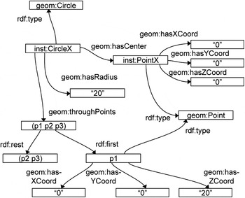
As semantic web technology enables a logic-based description of information with respect for its inherent syntax and semantics, this may well provide for an alternative approach on this file conversion process. Using the resource description framework (RDF; Manola & Miller, Reference Manola and Miller2004) and the Web Ontology Language (OWL; McGuinnes & van Harmelen, Reference McGuinness and van Harmelen2004), one is able to describe information in a directed labeled graph (Fig. 1), thereby making its inherent syntax and semantics explicit. Because this description is based on a specific kind of logic, most often description logic (Baader & Nutt, Reference Baader, Nutt, Baader, Calvanese, McGuinness, Nardi and Patel-Schneider2003), a considerable reasoning process can be developed based on the information contained within this directed labeled graph. Using an appropriate rule language, one can finally describe which new information can be derived from which existing information in rules that can be processed by a reasoning or inference engine (Berners-Lee et al. Reference Berners-Lee, Connolly, Kagal, Scharf and Hendler2008).
A directed labeled graph describing three-dimensional information.

A semantic web approach was already suggested to improve the interoperability of computed-aided design (CAD) information, for instance, by Abdul-Ghafour et al. (Reference Abdul-Ghafour, Ghodous, Shariat and Perna2008). Using semantic web technology, one should be able to describe 3-D information, which is otherwise contained in a file according to a schema, in a directed labeled graph, thereby describing its syntax and semantics in basic logical terms. This graph description allows the description of relations between different schemas. Abdul-Ghafour et al. (Reference Abdul-Ghafour, Ghodous, Shariat and Perna2008) indicates how this allows the combination of information from several different knowledge domains, enabling a seamless coupling of 3-D information with nongeometric information, such as design intent and domain-specific product features. We similarly presented in Pauwels et al. (2011) how semantic web technology enables the integration of various architectural design information to the AEC and 3-D information available through the IFC schema. Using a rule language, one can reuse this information logically and generate new information, for instance, to retrieve semantic relationships between features (Abdul-Ghafour et al., Reference Abdul-Ghafour, Ghodous, Shariat and Perna2008) or to make an acoustic performance calculation for a building design (Pauwels et al., Reference Pauwels, De Meyer and Van Campenhout2010).
Whereas these researches give a general overview of how semantic web technology might be an appropriate alternative track to enable the interoperability of information between different application domains in the AEC field, they do not really handle the combination of multiple different schemas for the description of the same 3-D information. Many important issues in the exchange and conversion of 3-D information are, however, typically caused by the presence of multiple schemas for the same information, mainly corresponding to the 3-D kernel used and to the application domain at hand. We argue that, instead of suggesting extra alternative standards or neutral formats for describing 3-D information, a way should instead be found to connect these diverse ways of describing 3-D information directly and consistently, a goal that may be achieved using semantic web technologies. Using a rule language, one can, for instance, explicitly describe how a description of a sphere according to one schema should be converted into a description of a 3-D mesh in another schema, and how a description of a 3-D mesh in the latter schema can be converted into a description of a sphere in the former schema, and so forth. This information may be inferred just in time, or stored explicitly as an addition to the original semantic graph, as a separate semantic graph, or maybe as a part of the global linked data cloud, explicitly connected to lots of other relevant information (Bizer et al., Reference Bizer, Heath and Berners-Lee2009).
In this paper, we will document our investigation of the applicability of semantic web technologies for the conversion of 3-D information in the light of design practices in the AEC domain and its inherent file conversion scenarios. In this investigation, we survey the schemas underlying 3-D file formats and 3-D modeling kernels often used in this domain, explicitly focusing on the syntax and semantics of the 3-D information. This survey is compared with existing approaches regarding the conversion of 3-D information, thereby pointing to important challenges that may be addressed with semantic web technologies. A new approach is proposed for file format conversions based on semantic web technologies. This approach is tested within two test cases, which will be documented in this paper. We stress that only a preliminary first investigation is documented here, and more research needs to be done to indicate the practical feasibility of using semantic web technologies for 3-D information management. The documented test cases are in this first step meant as an indication of how the conversion process could ideally take place, and they are therefore deliberately kept fairly simple. Whereas the theoretical feasibility seems clear from the test cases, more complex and in-depth test cases are needed to conclude the practical usability of the suggested semantic web approach, which is out of scope for this paper.
2. CHALLENGES IN THE EXCHANGE OF GEOMETRIC INFORMATION
2.1. A survey of schemas describing 3-D information
To improve our understanding of the exchange of geometric information, we started a survey of schemas describing, among other information, 3-D geometry. This survey did not target an exhaustive investigation of these schemas, but instead aimed at investigating the schemas most often relied upon in the AEC domain, in the light of understanding the nature of the situation in general. In this survey, we considered the schemas underlying both file formats (e.g., DXF, DWG, FBX, etc.) and 3-D modeling kernels (e.g. ACIS, PARASOLID, etc.).
An appropriate investigation of the schemas used by 3-D modeling kernels is of considerable importance. Because they lie at the core of all major applications for CAD and other CAx applications, they are always the first to describe geometry and thus also the most original source in a range of conversions of 3-D information. This paper solely documents the conversion of explicitly geometric information, leaving out as much as possible information like product data, building information, and so forth, because this was studied before in Abdul-Ghafour et al. (Reference Abdul-Ghafour, Ghodous, Shariat and Perna2008) and Pauwels et al. (2010), for example.
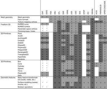
The results of the survey on schemas for 3-D information are summarized in Figure 2. One can see how each schema has its own set of supported geometric entities, which causes problems when converting geometric information from one schema to another. When an entity of the source schema is not supported by the target schema, a translation process is needed, often resulting in a loss of information due to reinterpretation and rephrasing of both syntax and semantics.
A selection of geometric entities that can be described within several different schemas. Blank fields indicate entities that are not defined in the specifications.

The OBJ schema, for instance, is often used as a neutral file format to store 3-D information independently for future reuse in 3-D applications. As can be found in Figure 2, the OBJ file format mainly supports a 3-D mesh description of geometric information. The information that the mesh might, for instance, be a sphere, is thus inevitably lost when converting it to the OBJ schema. This reduction to a 3-D mesh description is a common approach taken in the design and implementation of conversion processes on 3-D information. Because nearly every 3-D object can be described in terms of a 3-D mesh, almost no effort is needed in imagining and implementing this specific conversion process, allowing the loss of useful information to occur at least as frequently.
Figure 2 also shows that modeling kernels have their own sets of supported geometric entities, different from the ones supported by file formats. Therefore, information loss can already occur when saving a file in the 3-D modeling application, because a conversion has to be made from the schema of the modeling kernel to that of the file format. Saving geometric information described in the open cascade kernel to the DWG schema, for instance, inevitably leads to a loss of the concepts that have no equivalent in the DWG schema (e.g., hyperbola, parabola).
2.2. A matter of syntax and semantics
The schemas deployed when describing geometric information each show a unique semantics and syntax. In converting between these schemas, one has to cope with these differences. This inevitably leads to a loss of syntax and/or semantics due to misinterpretations and/or necessary reductions. Four scenarios can be distinguished concerning semantics and syntax, each with its corresponding approaches in handling these syntactic and/or semantic similarities and differences.
1. Same semantics, same syntax: An exact mapping of the 3-D information is possible. The converted description defines the object with exactly the same semantics and syntax. Unfortunately, this almost never occurs.
2. Same semantics, different syntax: If both schemas have exactly the same semantic understanding of a concept, however expressed within a different syntax, the information can easily be converted just by mapping the information to the correct information structure. This does not occur often either.
3. Different semantics, different syntax: In most cases, both semantics and syntax are different. In this case, the geometric information needs to be interpreted and rephrased into a description that is supported by the target schema. This conversion needs to be done with as much fidelity as possible to the original semantics and syntax, and not merely as a “best possible attempt” at the most resembling visual representation. This is a hard process, because many interpretations may be identified and even more translations of these interpretations can occur.
4. No possible equivalent: If a schema allows the description of information that is entirely not considered in a second schema, then conversion of this information is impossible. In this case, a complete loss of information is inevitable.
2.3. Dealing with semantics and syntax in the exchange of 3-D information
The ways in which the above similarities and differences in semantics and syntax are handled are diverse and have their respective consequences. We give a brief and general overview of the approaches commonly followed and their respective consequences on the information exchange.
2.3.1. One to one approach
In a one to one or point to point conversion approach ontology engineers generally focus on only two schemas that need to be mapped, and design and implement the implementation process of this particular conversion process. They are required to handle the similarities and differences in semantics and syntax in this design and implementation. Because they are limited to two schemas only, a very specialized conversion process may be designed without needing to keep in mind consequences with regard to other schemas. A description in DWG of a primitive concept such as a box, may, for instance, be converted into a 3-D mesh description in stereo lithography format (STL), because the ontology engineer assumes that the STL model is not to be reused any further than in a STL environment (e.g., rapid prototyping application). When dealing with a difference in both semantics and syntax, the interpretation and rephrasing of the geometric description is thus not influenced by requirements indirectly imposed by other schemas.
A major disadvantage is the number of conversion processes required for a sufficient effectiveness. Considering the rate in which new schemas and versions of those schemas emerge, this may require an unrealistic amount of engineering work. This is typically solved by concentrating on the major conversion processes used and needed, while leaving out the other processes. A second disadvantage emerges when a user goes through several conversions in a row. The more conversion processes are gone through, the more information gets reinterpreted and rephrased according to the design of the ontology engineer, inevitably leading to an increased information modification and information loss. This may be encompassed by searching for alternative “conversion routes,” which may have, however, its consequences on other parts of the 3-D description and so forth.
2.3.2. One to many approach
As a result of the disadvantages found in the one to one approach, one may choose to engineer a universal or “neutral” data format, able to describe all the information that may occur in each of the required schemas. This may prove an optimal approach when a “standard” procedure is followed, with an equally rigidly following conversion process, or when not that many schemas are used. However, this seldom occurs in the AEC domain, in which a significant amount of specialized application domains are addressed, each following their own sets of schemas, and in which almost never a “standard” design procedure is followed, let alone an equally rigidly following conversion process.
Consequently, the neutral data format tends to grow to inefficient sizes, incorporating too many possible, alternative descriptions for what is actually the same thing. This makes it extremely difficult for specialized applications in equally specialized application domains to import and export to this neutral data format, let alone be completely compliant with it. Many “bad import/export implementations” inevitably result, converting information with a highly elaborated semantics and syntax to a neutral, but not reusable geometric description.
An example of this situation can be found in the BIM approach (Eastman et al., Reference Eastman, Teicholz, Sacks and Liston2008), possibly in combination with the IFC standard (Liebich et al., 2009). As long as one stays within “the standard track,” or within one and the same BIM product suite, everything goes fine. As soon as one leaves the standard track and uses more specialized applications or perhaps more “exotic” applications, which is often the case in a design and construction context, enormous difficulties arise to keep the “central” BIM model appropriately up to date, let alone to efficiently and correctly communicate all the available information between the specialized applications and the BIM model.
2.4. Back to the roots
As is outlined by Gerbino (Reference Gerbino2003) and as was concluded from our survey on schemas for 3-D information, import or export processes always involve a conversion process to the internal structure of the 3-D modeling kernel of the 3-D application. Because this kernel deploys its own internal structure and algorithms with its inherent proprietary semantics and syntax, an in-house translation of any neutral or proprietary schema to this kernel structure is needed. A good strategy would thus be to use applications that rely on one and the same modeling kernel, and then to exchange 3-D information in this kernel's native format (e.g., SAT for ACIS).
A major drawback is the absence of detailed feature information in a kernel's native format, such as object classification details (e.g., wall objects, car wheel attributes, etc.), which is available in specialized schemas and neutral data formats. As an alternative, one would most probably choose to follow one product suite from one product vendor, assuming that this vendor uses one modeling kernel and has a sufficient knowledge of mapping geometric information between its own schemas. This limits, however, the user in choosing the “more appropriate” application for the task, and it essentially brings us back to the initial one to one approach documented above, although relying on only a limited number of schemas.
2.5. Let us go over the Web
An alternative approach suggested for enhancing the exchange and reuse of 3-D information is to follow an approach that is not file based. By storing all 3-D information in an online repository, several different applications could refer to this central location and provide modeling functionality based on this information. Subsequent applications for visualization or simulation, for instance, could refer to the same repository, and provide alternative modeling functionality based on this information.
Several 3-D shape repositories are currently available online, including the AIM@SHAPE repository (AIM@SHAPE Website, 2010), the 3-D CAD browser repository (3-D CAD browser Website, 2010), the Stanford 3-D Scanning Repository (Stanford Repository Website, 2010), and the Princeton Shape Benchmark (Shilane et al., Reference Shilane, Min, Kazhdan and Funkhouser2004). These repositories host a whole range of 3-D models and 3-D shapes, and make them available online through the appropriate browse and query functionality. Most of these 3-D geometry repositories appear to store information in one central file format and possibly refer to the appropriate 3-D conversion tools to obtain the same geometry in a different file format. The Stanford 3-D Scanning Repository, for instance, offers 3-D models mainly in their in-house file format, namely, the polygon file format. The 3-D models in the Princeton Shape Benchmark were retrieved from the World Wide Web through several automated Web crawls targeting specific file formats (e.g., VRML, 3-D studio, Autocad, Wavefront, Lightwave). The retrieved models were converted to a central schema, namely, the object file format, and stored as such in their repository for information retrieval and geometry matching (Shilane et al., Reference Shilane, Min, Kazhdan and Funkhouser2004). Notwithstanding the several benefits of these online 3-D repositories, they do not provide an answer to the issues encountered when exchanging 3-D information between several 3-D modeling applications, as providing a 3-D description in a single or only a limited number of schemas does not solve any issues in the conversion between schemas. Other 3-D geometry repositories, such as the 3-D CAD browser and the AIM@SHAPE repositories, provide 3-D models in a range of file formats (e.g., MAX, 3DS, DXF, OBJ, and WRL). However, for each of the 3-D models only one of these representations appears to be made available, instead of supplying the user with diverse, interlinked 3-D information schemas for each of the 3-D models. Consequently, the conversion problem is merely shifted back to the user, who is still forced to rely on third-party conversion tools if the required 3-D format is not available, and no significant improvements are thus generated regarding the reusability of 3-D information in diverse CAD applications.
The AIM@SHAPE repository nonetheless deploys semantic web technology to improve similarity matching and querying functionality. By annotating the 3-D models semantically with nongeometric information, for instance, regarding the classification of parts of the model (e.g., arms and legs on a human body), an improved search over the information is possible. In this approach, semantic web technologies are deployed to link specific parts of a 3-D model to semantic web information, thereby adding meaningful information to purely geometric concepts (Biasotti et al., Reference Biasotti, Giorgi, Marini, Spagnuolo and Falcidieno2006; Attene et al., Reference Attene, Robbiano, Spagnuolo and Falcidieno2007). These semantic web technologies may also address the challenges identified earlier regarding the exchange of 3-D information itself. By describing the diverse schemas for geometry information semantically, one obtains a universal and logical structure of the semantics and syntax of each of these schemas, which may then be linked explicitly. One description of a 3-D model is then implicitly available in other schemas as well, because the relations between these schemas are described explicitly.
3. THE SEMANTIC WEB
In this section, an overview is given of common semantic web technologies. Because extensive documentation on these technologies exists elsewhere (Berners-Lee et al., Reference Berners-Lee, Hendler and Lassila2001; Brickley & Guha, Reference Brickley and Guha2004; Grant & Beckett, Reference Grant and Beckett2004; Manola & Miller, Reference Manola and Miller2004; McGuinness & van Harmelen, Reference McGuinness and van Harmelen2004; W3C Semantic Web Portal, 2010), this overview will be kept brief and limited to the concepts needed for understanding the following sections.
The semantic web was conceived in Berners-Lee et al. (Reference Berners-Lee, Hendler and Lassila2001) as a semantic network that describes the meaning of its concepts through a directed labeled graph (Fig. 1). Each node in this graph represents a concept or object in the world and each arc in this graph represents the logical relation between two of these concepts or objects. In this way, the graph represents a set of logic-based declarative sentences. By describing information in a single directed labeled graph, a uniform description of information is targeted, both syntactically and semantically, making information reusable by both humans and computers. The semantic web is often referred to as a web of linked data (Bizer et al., Reference Bizer, Heath and Berners-Lee2009), implying all kinds of data to be linked together resulting in World Wide Web of information that both humans and machines can understand.
3.1. Resource description framework
The semantic web relies on the RDF as a language to represent its graph structure as an RDF graph (Manola & Miller, Reference Manola and Miller2004). An RDF graph is constructed by applying a logical AND operator to a range of logical statements containing concepts or objects in the world and their relations. The directionality of the RDF graph is realized through the “RDF triple” structure, and the graph is labeled with unique resource identifiers (URIs) for both concepts and relations. An RDF graph can be converted into a textual representation that follows a specific syntax, such as RDF/XML, N-Triples (Grant & Beckett, Reference Grant and Beckett2004), Turtle (Beckett & Berners-Lee, Reference Beckett and Berners-Lee2011), SPARQL (Prud'hommeaux & Seaborne, Reference Prud'hommeaux and Seaborne2008), and Notation-3 (N3; Berners-Lee & Connolly, Reference Berners-Lee and Connolly2011). We use the N3 syntax because it focuses on human readability and the possibility to express both data and logic in the same language (Berners-Lee & Connolly, Reference Berners-Lee and Connolly2011).
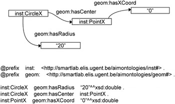
Figure 3 illustrates how a circle may be described using N3. The first two statements define two prefixes (“inst:” and “geom:”) that enable the abbreviation of the URIs used in the RDF statements below. Using the “inst:” prefix, for instance, one can reconstruct the URI of the resource “inst: CircleX” into “http://smartlab.elis.ugent.be/aimontologies/inst#CircleX.” The lower lines describe two statements about the concept “inst:CircleX,” concatenated by a point as a representation of the logical AND operator. The predicates “geom:hasRadius” and “geom:hasCenter” label the logical relations attached to the “inst:CircleX” concept.
Semantic web description of a circle, both in a visual graph and an N3 representation.

3.1.1. Web ontology language
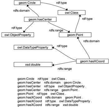
RDF graphs can be given an improved semantic structure using RDF vocabularies or ontologies. The most basic elements to describe such ontologies are available in the RDF Schema (RDFS) vocabulary (Brickley & Guha, Reference Brickley and Guha2004). More expressive elements to describe ontologies are available within the OWL (McGuinness & van Harmelen, Reference McGuinness and van Harmelen2004), which uses RDFS concepts as a subset. The RDF graphs constructed with OWL concepts are called OWL ontologies, and they can be used as an available vocabulary when making other, more complex RDF statements (see Fig. 1, Fig. 3, and Fig. 4). By extending an RDF graph with this OWL functionality, virtually any kind of information can be described semantically.
An OWL ontology for describing parts of a circle.

3.1.2. Rule languages
The available RDFS and OWL concepts enable only a basic, standard level of reasoning, limited to a certain level of complexity. When a more complex logical reasoning is necessary, one should describe rules explicitly in a more dedicated rule language. Using a specific rule language, one is able to define custom rules and subsequently use them in a rule-based reasoning process. Several rule languages have been developed to express such logic. Three of the most notable initiatives in the semantic web domain are the semantic web rule language (SWRL; Horrocks et al., Reference Horrocks, Patel-Schneider, Boley, Tabet, Grosof and Dean2004), the rule interchange format (RIF Working Group Website, 2010) and N3Logic (Berners-Lee et al., Reference Berners-Lee, Connolly, Kagal, Scharf and Hendler2008).
These rule languages aim to do for logical information what RDF does for data: to provide a common data model to express globally sharable information on logic. They enable information with a far greater expressive power, such as rules, to be shareable similarly to the way in which RDF is sharable. Having one rule described in such a rule language, any other agent should be able to understand this rule and possibly apply it within a completely different situation and environment.
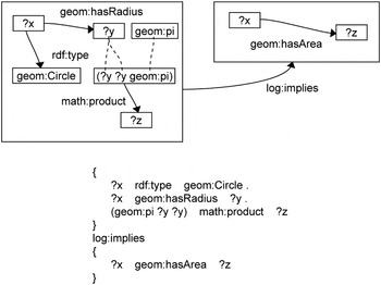
We are currently using N3Logic to describe rules. A rule in N3Logic contains hypothetical “formulae.” Every hypothetical formula thereby uses curly brackets in its syntax to describe a subgraph, that is, a logical conjunction of the statements between the curly brackets (Berners-Lee et al., Reference Berners-Lee, Connolly, Kagal, Scharf and Hendler2008; Fig. 5). Rules typically represent an IF–THEN relation, thereby following the syntax of an RDF triple statement. The rule in Figure 5, for instance, specifies that IF an entity can be found that is of type “geom:Circle” AND that has a “geom:hasRadius” property that may be reused in a calculation π*requested output. The engine starts from the given requested output and applies only the inference rules that have the requested output in their THEN clause (Berners-Lee et al., Reference Berners-Lee, Connolly, Kagal, Scharf and Hendler2008).
N3Logic rule in its normative N3 notation.

3.2. Rule inference engines
Using rules and RDF graphs, a semantic rule engine or inference engine may infer new information. These reasoning applications typically return a conclusion consisting of a set of newly inferred triples or a proof that a certain statement is true or false. There are several types of semantic rule engines, depending on the inference method deployed. The CWM engine (Berners-Lee, Reference Berners-Lee2010), for instance, is a forward chaining reasoning engine, whereas the EYE reasoning engine (De Roo, Reference Van Ackere and De Roo2010) is actually a backward–forward–backward chaining engine (De Roo, Reference De Roo2009). We are currently using the EYE reasoning engine because of its backward chaining capabilities. Instead of just inferring all possible information that may be inferred from the rules and RDF graphs, this reasoning engine is able to determine which rules are necessary to provide a requested output. The engine starts from the given requested output and applies only the inference rules that have the requested output in their THEN clause (Berners-Lee et al., Reference Berners-Lee, Connolly, Kagal, Scharf and Hendler2008).
4. SEMANTIC WEB TECHNOLOGIES APPLIED TO THE EXCHANGE OF 3-D INFORMATION
From the background study on the exchange of 3-D information in the AEC domain and on semantic web technologies, we started an investigation of the adoption of semantic web technologies for the exchange of 3-D information between 3-D modeling applications. Instead of trying to convert a description of 3-D information according to one schema into a description in another schema, semantic web technologies could enable the coexistence and explicit interlinking of 3-D information in different schemas following explicit, logically described rules.
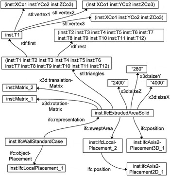
If the schemas used to describe geometric information can be converted into OWL ontologies, anyone could describe geometry according to these schemas in the semantic web graph, possibly as a part of the linked data cloud mentioned earlier (Bizer et al., Reference Bizer, Heath and Berners-Lee2009). As was indicated in Abdul-Ghafour et al. (Reference Abdul-Ghafour, Ghodous, Shariat and Perna2008) and Pauwels et al. (Reference Pauwels, De Meyer and Van Campenhout2010), this enables the coupling of the 3-D information with virtually any kind of information, including feature data, cost information, production details, material information, geographical information, design intent, historical references, and so forth. What we focus on in this paper, however, is that one may also be able to describe geometry according to several different schemas and link the descriptions together explicitly. A circle, as an easy example, may be explicitly described through its center and its radius, while in a second schema, it may be described as a circular line through three points. Similarly, a cube may in one schema be described by a location, an orientation and an edge length, while in a second schema, it may be described as a 3-D triangle mesh (Fig. 6).
A semantic web graph that links representations in the STL, X3D, and IFC schema.

Because the geometric information has several parallel descriptions, it will most probably be very difficult to modify the geometry and keep all parallel descriptions up to date. If a user wants to change the radius of the circle mentioned earlier, for example, he also needs to recalculate three points on this circle and update this information in the parallel description following the second schema.
The usage of rules may, however, solve this issue. One may consider a one to one conversion approach for several schemas, in which the one to one conversions are described explicitly using N3Logic rules. From the moment that a description of 3-D geometry is available in one schema, a description is also available in each of the schemas linked through the explicitly described conversion rules. Because the presence of these rules and an inference engine suffices for calculating the required descriptions, these descriptions may not have to be stored explicitly, but can be inferred just in time.
5. TEST CASE: CONVERTING IFC OVER X3D TO STL AND BACK
5.1. Objectives of the double test case
We investigated the suggested semantic web approach and its implementation details in the twofold test case documented here. Note that we deliberately do not focus on the integration of feature information or any other nongeometric information that might be relevant in the AEC field, because this is already handled elsewhere (Abdul-Ghafour et al., Reference Abdul-Ghafour, Ghodous, Shariat and Perna2008; Pauwels et al., Reference Pauwels, De Meyer and Van Campenhout2010). Instead, we focus solely on the conversion and integration of diverse schemas describing the same 3-D information. In addition, we limit the double test case to a fairly simple example just to indicate the suggested conversion methodology. A full in-depth study of a whole range of more complex test cases is required to indicate the practical feasibility of the approach, which is out of scope for this paper and subject to ongoing research. Of course, only part of the rules can be documented here; therefore, the interested reader is referred to Van Ackere and De Roo (Reference Van Ackere and De Roo2010) for a full overview of the rules deployed.
The first test case investigates the adoption of semantic web technologies in a file conversion process starting from a semantically “rich” schema to a semantically “poor” schema, whereas the second test case essentially aims at going back. In the distinction between semantically rich and poor, we mean that the concepts in the poor schema are all present in the rich schema and are extended with extra concepts. Where the first schema is, for example, only able to describe triangles through their vertices, the other adds information regarding primitive types or geometric topology, and so forth. The first test case, from rich to poor, should therefore be easier than the reverse test case.
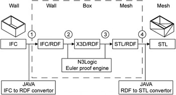
Conversion of 3-D information in IFC into 3-D information in STL.

In our test cases, we chose the geometry schema of the IFC as representative for the rich schema and the STL as representative for the poor schema. Both test cases went through an intermediate step, namely, over an extensible 3-D (X3D) description of the information, in order to evaluate how intermediate steps may influence the overall conversion processes. The overall conversion process is presented for the first test case in Figure 7. It comprises the four conversion steps given below.
1. IFC to IFC/RDF: The native IFC description is converted into an IFC/RDF description using our in-house IFC to RDF service (UGent Multimedialab, 2010a).
2. IFC/RDF to X3D/RDF: Conversion through a dedicated N3Logic rule set as part of the test case.
3. X3D/RDF to STL/RDF: Conversion through a dedicated N3Logic rule set as part of the test case.
4. STL/RDF to STL: The conversion of the STL/RDF information to a native STL description is done by a JAVA rewriting application.
5.2. Brief description of the schemas used
The formal EXPRESS schema of IFC (Liebich et al., 2009) enables a description of construction-related information through a network of entities, select types, enumerations, attributes, collections, relations, and so forth. As such, it contains far more information than just 3-D geometry, including product data about building walls, window types, and so forth. It is usually generated as an export of BIM environments, which combines all kinds of information on a building design in one BIM model (Eastman et al., Reference Eastman, Teicholz, Sacks and Liston2008). The IFC description generated for such a BIM model can subsequently be used as an input for a range of simulation, calculation, and visualization applications.
The X3D schema is an XML-based schema for the description of computer graphics information, designed as a successor of the Virtual Reality Modeling Language (VRML) by the Web3D consortium (Web3DConsortium Website, 2010). It is an open standard for real-time 3-D graphics communication on the World Wide Web. It provides support for many different types of information, including material and lighting information, for instance, making the format usable for many domains, such as architecture, entertainment, multimedia, and engineering.
The STL schema was originally designed by 3-D systems to be used by their stereo lithography machines. These machines are basically 3-D printers that can reproduce any solid model as a series of slices, resulting in a printed physical model. Because these machines only need a raw description of the 3-D geometry, it suffices to describe the solid model as a closed triangulated surface. Although this file format is outdated, many CAx systems still use it for data exchange, because the limited amount and simplicity of information largely prevents misinterpretation of information and thus a wrong import or export of information.
5.3. Test case 1: IFC to STL
5.3.1. IFC to IFC/RDF
A simple 3-D model was created using a standard BIM environment, namely, Autodesk Revit Architecture 2010, only containing four connected wall objects with a boxlike shape. From the BIM environment, an IFC description was exported using the standard available export functionality provided by Autodesk. The resulting IFC description describes our model as a combination of four “IfcWallStandardCase” concepts with both purely geometric (e.g., position, representation, etc.) and extra product information (e.g., material, cost, etc.) attached. This IFC description is then converted into an IFC/RDF graph by our IFC to RDF Web service (UGent Multimedialab, 2010a) and made accessible through a SPARQL endpoint (UGent Multimedialab, 2010b). The IFC to RDF service relies on an OWL ontology for IFC that is designed as an exact reflection of the original EXPRESS schema (Liebich et al., 2009), similar to how it was suggested by Beetz et al. (Reference Beetz, van Leeuwen and de Vries2009). This implies an almost identical syntax and semantics, which in turn enables the most optimal conversion process possible with a minimal amount of information loss. Further design and implementation details of the IFC to RDF Web service are out of scope for this paper, but can be found in Pauwels et al. (Reference Pauwels, De Meyer and Van Campenhout2011).
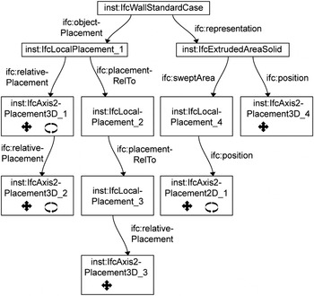
The geometry of the “IfcWallStandardCase” concepts is described in the resulting IFC/RDF graph through “IfcExtrudedAreaSolid” concepts that are each in turn described by an extruded direction, a depth and a rectangular profile defining the base profile or “swept area.” The positions of the wall objects are described by a series of rotations and translations, all relative to each other, following the overall structure displayed in Figure 8.
Overview of how the location of an “IfcWallStandardCase” is described in the IFC/RDF graph as a series of relative rotations and translations.

5.3.2. IFC/RDF to X3D/RDF
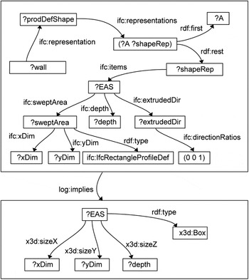
The resulting IFC/RDF graph may then be converted into an X3D/RDF graph through a set of N3Logic rules. Starting from the IFC/RDF description found, we searched for the most appropriate concepts in the X3D specifications to rephrase the IFC/RDF information with. The schema of X3D does not include any notion of a wall object, let alone its product data. This information therefore needs to be disregarded in the conversion process. As 3-D primitives were found to be part of the X3D schema, the descriptions of the wall objects are converted into the corresponding descriptions of X3D boxes and linked to the original IFC/RDF descriptions. A rule describing part of this conversion process is displayed in Figure 9. Note that for other IFC concepts, such as doors, windows, floors, railings, and so forth, a similar process can be followed and rules can be obtained for the conversion of these IFC objects to the appropriately corresponding X3D objects. An analogous conversion process can presumably be followed for the further conversion into an STL description and an overview of this process is consequently left out of this paper.
N3Logic rules creating a box description according to the X3D specifications with its additional dimensions.

The X3D schema describes the position of objects differently from how it is described in IFC. Instead of defining the position of a point through a whole set of relative transformations of both the position and orientation of the object (Fig. 8), X3D describes the location of an object through a combined translation matrix and rotation matrix relative to the world coordinate system used. These translation and rotation matrices can be inferred from the sequence of relative transformations of both the position and orientation as described in IFC. For each relative transformation, a rotation and translation matrix is calculated iteratively by the backward-chaining reasoning engine using specific N3Logic rules, after which another rule set in N3Logic performs the required matrix calculation on these matrices (Van Ackere & De Roo, Reference Van Ackere and De Roo2010). The eventually resulting translation and rotation matrices are added to the X3D/RDF graph.
5.3.3. X3D/RDF to STL/RDF
A third step comprises the conversion of the X3D/RDF graph into a STL/RDF graph. A similar methodology is followed as in the previous conversion step, starting with a search over the X3D and STL specifications for the appropriate STL concepts to be used for representing the available X3D concepts. Because the STL schema allows the description of geometry only through its triangles, the X3D/RDF box description needs to be converted into a 3-D mesh description in STL/RDF.
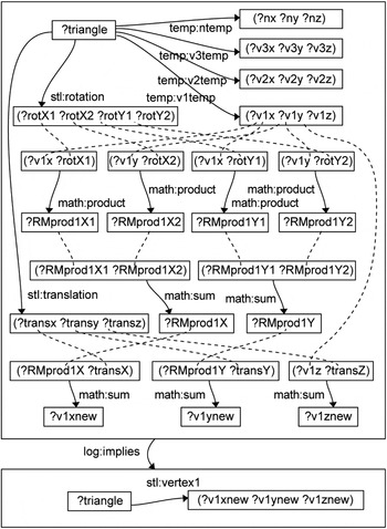
This mesh description refers to a set of triangles, each in turn described by its normal and vertices. This is again a completely different description compared to the description of a primitive box in the X3D schema. The conversion rules go through a whole range of matrix calculations to obtain these coordinates and convert these in a correct description of all the triangles in the mesh. One of these rules is given for reference in Figure 10.
N3Logic rules describing the recalculation of the normal vector coordinates and of the vertex coordinates of one triangle in the STL mesh.

5.3.4. STL/RDF to STL
In a final phase, the STL/RDF graph is converted into a STL file, using a JAVA rewriting application. Because the STL/RDF ontology follows the syntax and semantics of the schema of STL, an easy one to one mapping can be followed. Importing the resulting STL file in a 3-D modeling application, such as Rhinoceros 3-D, indicated a correct conversion of the 3-D information. Tests with several other simple models indicated an equally successful process, as long as the concepts with which they were described are incorporated in the rule set.
5.4. Test case 2: STL to IFC
The second test case concentrated on the backward conversion process. Note that in the above test case, the newly inferred information is added to the original information and stored in the same graph as the original IFC/RDF graph. This implies that one knows that the STL/RDF triangles actually represent IFC wall objects or an X3D box object and also the once available product data, such as cost and material information, is still available in an STL context. In this case, no backward conversion process is needed because all the original information describing the IFC wall object according to the schema of IFC, is still present and can be used (Fig. 6). This is already an important improvement over the existing approaches toward 3-D information exchange in the AEC domain, as these approaches almost always lose or distort this information during the conversion processes.
However, if only the STL/RDF graph is available, no explicit statement exists saying that part of the STL/RDF graph, for instance, represents an IFC wall object or an X3D box object. This second test case investigated whether semantic web technologies could also provide help in this situation. The original test model was therefore remodeled inside a Rhinoceros 3-D modeling environment, and exported into an STL format. This was then converted into a semantic STL/RDF graph using the same JAVA application previously used. From this STL/RDF graph we tried to describe rules that can infer that this set of STL triangles actually represents a set of four IFC wall objects or four X3D box objects. The original description is thus semantically enriched using these rules.
These rules explicitly describe interpretations, or presumptions based on specific conditions. The description of these rules is therefore crucial and should be handled with extreme caution and care. It might seem correct to infer that a geometrically closed object bounded by three pairs of parallel faces, can be considered a box object or an “IfcExtrudedAreaSolid” based on a rectangular profile. Inferring that a box with a certain height, width, and depth actually represents an “IfcWallStandardCase” concept is quite another matter. This requires contextual information if a sufficiently reliable result is needed, which is often not available in the original 3-D model description and thus needs to be added by a human user.
We nevertheless proceeded with the test case to see how far it goes. Starting from the STL/RDF graph, we went through the following steps for adding extra semantics based on the geometric representation solely.
1. extending the geometric information (e.g., identification of edges, adjacent triangles, etc.);
2. geometry recognition: infer the attributes required to describe the geometry according to a specific schema (e.g., depth and width attributes); and
3. feature recognition: infer extra information, such as identification of wall objects and door objects.
5.4.1. Extending the geometric information in the STL graph
The STL/RDF graph describes 3-D geometry through a set of unrelated triangles, described uniquely by the coordinates of the vertices of these triangles. The STL/RDF graph does not describe which triangles are neighboring, let alone over which edge they might be neighboring; neither is it known whether some of the edges are parallel to each other, and so forth. This information, however, may be inferred from the explicit STL/RDF graph. This information is thus implicitly present in the STL/RDF graph and may be retrieved using a set of N3Logic rules, similar to how it was done in the first test case.
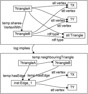
An example of how one may infer if a triangle has a common edge with another triangle, including naming this particular common edge, is given in Figure 11. The triangles that were previously identified as possibly adjacent triangles are checked and identified as neighboring triangles if they have two vertices in common. In addition, the common edge is explicitly named through its two vertices and two adjacent triangles. In a similar fashion, one can easily describe rules able to infer whether faces are parallel to each other, for instance (Van Ackere & De Roo, Reference Van Ackere and De Roo2010).
N3Logic rules for inferring which edges are neighboring with which edges.

Once all adjacency information is added, this information can be used to derive separate objects described by the triangles. In our rules, we defined such an object as a set of triangles each having at least one neighboring triangle (Van Ackere & De Roo, Reference Van Ackere and De Roo2010). Using these rules, the EYE inference engine loops through all the triangles and finds such objects instantaneously. This process repeats until each object is found and described through its triangles. As one can conclude from the definition, these objects are both closed and open meshes of triangles. The explicit distinction between these objects is nevertheless possible using additional rules that identify objects of which the triangles all have exactly three adjacent edges or neighboring triangles (Van Ackere & De Roo, Reference Van Ackere and De Roo2010).
A rule set similar to the one used to identify objects, allows the identification of separate faces in these objects. A face is in this regard considered as a set of triangles all having at least one neighboring triangle within the set of triangles identifying an object AND having the same normal vector or orientation as this neighboring triangle. Based on the information available at this point in the RDF graph, also extra information may be inferred about the faces in the model. Each face has the same normal vector as the ones linked to the triangles that are part of these faces. An appropriate interpretation of these vectors, for instance, allows the identification of parallel faces, similar to how parallel triangles were identified (Van Ackere & De Roo, Reference Van Ackere and De Roo2010).
5.4.2. Geometry recognition
Using the extended geometric information derived in the previous steps, one may describe rules that enable the recognition of 3-D primitives. In this test case, these geometry recognition rules were developed only for a box primitive. A 3-D object in the STL/RDF graph is considered a box primitive if the object consists of exactly three pairs of parallel faces. The lengthy rule set used can be found in Van Ackere and De Roo (Reference Van Ackere and De Roo2010).
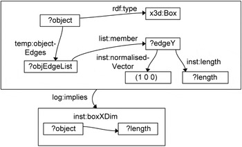
Because the edges of the faces of this box differ from the edges of the STL triangles, the respective length of each of these edges cannot be inferred directly. It requires the explicit identification of these face edges, linked to the coordinates of the triangles they consist of. The length of each of the edges of this box object can be inferred as the sum of the lengths of all triangle edges that are part of the face edge. This inference requires a lengthy rule set that is not described here for reasons of brevity. One of the rules for inferring the eventual dimension along the x-axis is displayed in Figure 12. At this time, we were only able to infer this information for boxes oriented according to the world coordinate system. More complex rules are normally able to infer this information for other box objects as well.
N3Logic rules for inferring the dimension of a box along the x axis.

From this information, one may easily infer an RDF graph following the X3D schema. However, the elaborate set of rules that resulted from this test case for the quite simple inference that this 3-D model actually represents a box primitive should be taken into account when considering the recognition or identification of more complex geometry through semantic web technologies. Note also, on the other hand, that once the above rules are available, a lot of implicit information is available automatically for any STL/RDF graph, which can be reused or extended as wished.
5.4.3. Feature recognition
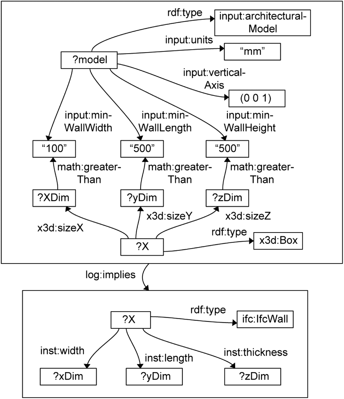
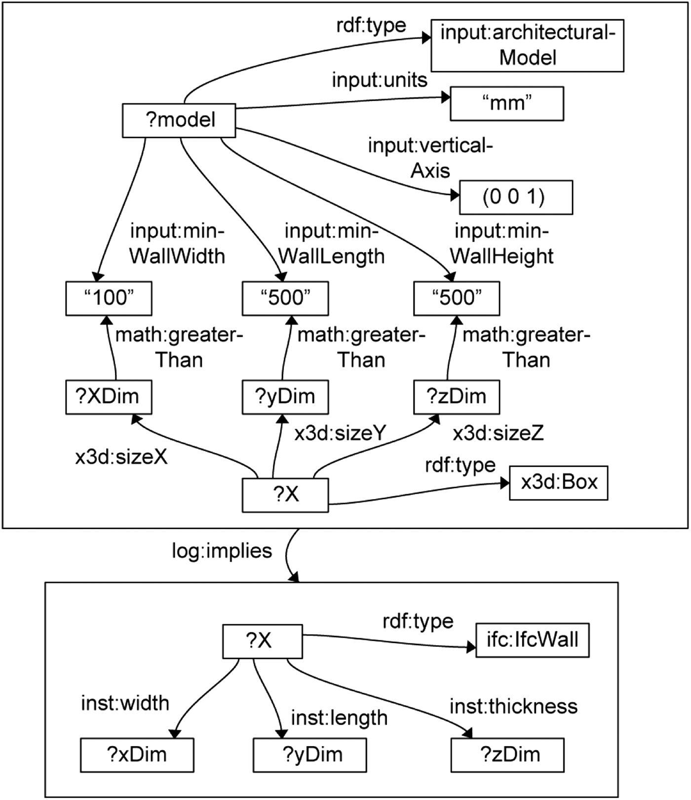
The inference that the box described through the X3D/RDF graph inferred through the rules documented above actually represents a wall object seems a more challenging inference. Not a lot of information in the X3D/RDF and STL/RDF graphs at this stage of the inference process indicates that the model described is even part of a building, let alone that it represents a wall object. Only the information on the dimensions of the 3-D objects might give an indication that the object described actually is a wall object. One might decide, for instance, that any box object that is approximately 2 m high, 30 cm wide, and more than 1 m long is a wall object. In addition, one can define upper limits for these dimensions as well. This may enable the distinction between wall entities and other building entities, such as doors, columns, windows, floors, and so forth. Note, however, that any building entity that differs from its description in the rules, cannot be recognized. For instance, a wall object wider than the indicated 30 cm or shorter than 1 m, will not be recognized as a wall object. In addition, one has to be aware that blindly following this kind of assumptions can undoubtedly lead to very strange and incorrect results.
This inference may be enhanced significantly with the explicit confirmation of certain assumptions. An assumption that might easily be provided by the user, is that the object in question is part of an architectural model. Additional assumptions that may be confirmed explicitly by the user include the definition of a vertical orientation, a connection to a horizontal floor or ceiling element, explicit material information, and so forth. A user may confirm, for instance, that he or she is sure that no wall object wider than 30 cm or shorter than 1 m is present.
Figure 13 shows how a rule may rely on this kind of information to recognize a wall feature in the available RDF graph. This rule may be extended with more criteria in order to detect more specific types of walls. Once walls are recognized in this test case, enough information should be available in the RDF graph to convert it to a representative IFC file.
N3Logic rules describing how one may infer whether or not an X3D box represents a wall object.
6. DISCUSSION AND FUTURE WORK
This paper mainly targets a good indication of how the exchange and conversion of 3-D information could be enhanced using semantic web technologies. Therefore, the double test case was deliberately kept fairly simple. We are aware that far more complex examples are needed to fully test the practical feasibility of the suggested approach. Notwithstanding the simple example used throughout the double test case promising results were indicated for the indicated challenges in converting 3-D information. We want to stress here that the most important of these challenges essentially lies in the conservation of all information in its original schema, which was handled in the first part of the test case, and not in the successful automatic addition of semantic information, which was handled in the second part of the test case. The main issue is that 3-D information is in many cases (partly) changed or lost when it is introduced in another application. Part one of the test case indicates how the most original description can be maintained and kept available successfully in an RDF graph structure after the conversion of the 3-D information. When going back to the original application, it may rely on this description to restore the original.
The second, backward test case essentially attempts at adding information that is not available in the original description. This is a whole other objective, which has always required additional input from human users. The reasons why have become clear in the test case. When rules are described to identify a wall entity—or a door, window, floor, or any other entity for that matter—they define explicitly what a wall entity should conform to, whereas in real life very different interpretations may exist on what a wall really is. The example of a wall object defined by its maximum dimensions (Fig. 13) seems a good example in this respect: a wall may be defined by these dimensions, whereas another might distinguish a wall through its material structure. This indicates why blindly trusting the available rule set may result in curious, unexpected results, and why one may want to explicitly confirm some of the assumptions that are implicit in the rules.
Fortunately, the most important challenge in the conversion and exchange of 3-D information lies in the conservation of all information in its original schema, while other, parallel descriptions are generated. Although more complex examples are needed to fully confirm the approach, the semantic web approach appears able to meet this challenge, as was shown in the first test case.
The most important challenge to be handled in future research might be the conversion back to the original schema after changes are made in an alternative application. One can imagine how even a simple boxlike wall object that is described as an extruded rectangle in one application (e.g., AutoDesk DWG), needs to be converted to a 3-D mesh by the reasoning engine to be accepted by a second application (e.g., Google SketchUp). Because the wall entity is understood as a 3-D mesh in the second application, a completely different set of interactions is available on the object that might not be compliant with the interactions available in the original application, such as the addition of vertices or the free rotation and translation of edges in the 3-D mesh. When returning to the original 3-D modeling application, the original description in the RDF graph needs to be modified according to the changes made, which undoubtedly has its own challenges and implications. Should the new 3-D mesh information be semantically enriched using rule sets, similar to how it was presented in the second test case? Should the application use the original information in the semantic web for unchanged objects and rely solely on the 3-D mesh description of the second application for the changed objects? Are there other alternatives? These and other questions need to be handled in future research on the topic.
7. CONCLUSION
The inevitable conversion processes required to communicate 3-D information among CAx applications still generate significant burdens and limitations in the AEC domain. 3-D information is transformed into representations that are not reusable, parts of the 3-D information are lost, and so forth. As a result, designers and engineers in the AEC domain need to remodel the 3-D model into the description schema required, resulting in a loss of efficiency and an increased occurrence of construction errors.
We have investigated this situation through a survey of the schemas underlying several frequently used file formats and 3-D modeling kernels. This survey pointed out how each schema defines its own syntax and semantics, in many cases different from any other schema. Conversion processes need to map between the concepts deployed in the schemas considered. This requires a considerable effort from the ontology engineers designing these conversion processes. In many cases, the syntax and semantics of two schemas are considerably different. In this case, information needs to be reinterpreted and converted correctly in a different description.
An overview is given of approaches typically deployed in handling such mapping processes. Approaches discussed include the usage of neutral data formats, an exchange of 3-D information between the native 3-D modeling kernels and an exchange of 3-D information over the Web. Instead of adequately addressing the problem, they tend, however, to shift the conversion problem to somewhere else in the design process.
A new approach has subsequently been suggested in this paper, based on semantic web technology. This technology enables the description of information in a directed labeled graph, with the explicit inclusion of the syntax and semantics of the schema deployed using OWL ontologies. Because one can describe 3-D geometry following different schemas (e.g., STL, X3D, and IFC) within one and the same semantic web graph, no explicit conversion process needs to be gone through. If a representation following a certain schema is not available, one can deploy a rule engine and a set of conversion rules to infer this description from the information that is available. The mapping process that is normally designed and implemented in the traditional conversion processes, is now thus present in a set of rules explicitly following logic.
Through two test cases, we tested this semantic web approach. The first test case focused on the conversion from a semantically rich schema to a semantically poor schema, whereas the second test case focused on the backward conversion process. A simple building model was exported to the IFC schema and then converted into a semantic IFC/RDF graph. Rules were described to enable a successful conversion of this IFC/RDF information into X3D/RDF and STL/RDF information. In the second test case, rules were described enabling the reasoning engine to infer that a set of STL triangles represents an object with separately identified faces and edges, that it represents an X3D box object with specific dimensions, and subsequently that it represents a wall object.
The investigation documented in this paper indicates significant improvements to traditional conversion processes. 3-D information can be described following several schemas in one and the same semantic web graph, in addition, allowing the explicit description of links between these descriptions. The information that an STL triangle is, for instance, part of the description of a wall object is consequently not lost, as is normally the case in traditional approaches, but remains available in the semantic web graph. The usage of rule languages in addition enables the explicit description of the mappings followed in a conversion process. This explicit description of mappings in a set of rules enables an improved description of this mapping process compared to traditional procedural approaches, in addition, enabling ontology engineers to focus more in depth on this mapping process and improve it appropriately.
This paper has documented only an initial investigation of the deployment of semantic web technologies for the conversion of 3-D information in the AEC domain. Obviously, a further in-depth investigation is needed of the practical feasibility of this approach for a domain that incorporates lots of other, more complex geometric concepts next to the ones investigated in our test cases. This presumably requires the design of lots of additional rule sets, which may pose its own challenges as well. Nonetheless, the given overview provides a good insight in the improvements that might be generated when following this approach.
ACKNOWLEDGMENTS
This research is a combined effort of the UGent SmartLab and Multimedia Lab research groups, supported by the Interdisciplinary Institute for Broadband Technology and both the Department of Electronics and Information Systems and the Department of Architecture and Urban Planning of Ghent University. The project team gratefully acknowledges the funding support from the Research Foundation–Flanders.
Pieter Pauwels graduated from Ghent University as an engineer–architect in 2008 with theoretical research on the ICT conception of an integrated architectural design environment. He is currently preparing a PhD dissertation at the Department of Architecture and Urban Planning and the Department of Electronics and Information Systems of Ghent University. His PhD research focuses on how information may be deployed within ICT applications to generate useful support for the architectural designer in his design task. A framework is targeted for architectural information modeling (AIM), which is based on semantic web technology and 3-D modeling techniques.
Davy Van Deursen is currently a postdoctoral researcher at Ghent University—IBBT (Ghent, Belgium), where he is working for the Multimedia Lab research group. He received his MSc and PhD degrees in computer science from Ghent University, Belgium in 2005 and 2009, respectively. Between 2007 and 2009, he was involved in Siruna, a spin-off of IBBT and Ghent University. Since 2008, he has been actively participating within the W3C Media Fragments Working Group. His research interests and areas of publication include video coding, media content adaptation and delivery, multichannel publishing, media content presentation, semantic web technologies, advanced reasoning techniques, e-learning, and standardization.
Jos De Roo is researcher at Agfa Healthcare and doing advanced development of components to realize semantic web-oriented architectures for healthcare imaging applications, healthcare enterprise integration, and medical decision support. He graduated in 1979 as Master of Science and did a doctoral study on image computing from 1979 till 1982. He was Cofounder of ICOS (Image Computer Systems) and worked there until 1985. Since then, he has worked at Agfa. He is also involved in Euler proof mechanism open source development and in W3C Semantic Web Activity Working Groups.
Tim Van Ackere graduated at Ghent University as an engineer–architect in 2010 with a master's dissertation on geometric data exchange in architectural design practice where he explored the possibilities of semantic web technologies for use in geometric data conversion processes.
Ronald De Meyer is a Senior Lecturer in the Department of Architecture and Urban Planning of Ghent University and a Lecturer in the Department of Architecture and Design at the Provinciale Hogeschool Limburg. He graduated from the Hoger Architectuurinstituut van het Rijk, Antwerp, in 1978 and received his PhD with a dissertation on the development of the 19th century Antwerp town district Het Zuid from Catholic University Leuven in 1993. Dr. De Meyer's research involves 19th and 20th century construction history, more specifically, the role of concrete and iron structures in Belgium, and the intelligent deployment of ICT technology within the architectural design task.
Rik Van de Walle is a Professor of multimedia systems and applications and Head of the Multimedia Lab at Ghent University. He received his MS and PhD degrees in engineering from Ghent University in 1994 and 1998, respectively. After a visiting scholarship at the University of Arizona Tucson, he returned to Ghent University. Dr. Van de Walle's current research interests include multimedia content delivery, presentation and archiving, coding and description of multimedia data, content adaptation, and interactive (mobile) multimedia applications.
Jan Van Campenhout is Head of the Department of the Electronics and Information Systems Department (ELIS) of the Faculty of Engineering at Ghent University, where he teaches courses in digital design. He received a degree in electromechanical engineering from the University of Ghent in 1972 and MSEE and PhD degrees from Stanford University in 1975 and 1978, respectively. Dr. Van Campenhout's research interests include the study and implementation of various forms of parallelism in information processing systems, currently focused upon the modeling and design of short-range parallel optical interconnects from a systems perspective.