Introduction
Ultra-wideband (UWB) communications have high-frequency bandwidth with high data transmission speed, use of short pulse modulation to reduce fading effects due to the multipath received signal, and low power consumption due to low power spectrum density [Reference Saha, Siddiqui and Antar1, Reference Sarkar, Srivastava and Saurav2]. UWB technology can be widely used in impulse radio, high speed communications over short distances, medical applications, radars, sensors, positioning, and imaging [Reference Saha, Siddiqui, Freundorfer, Shaik and Antar3]. Printed broadband antennas are inexpensive and affordable, small in size, less complexity, and light in weight [Reference Saha, Shaik, Muntha, Antar and Siddiqui4]. UWB signals need to be protected against a higher power and low bandwidth interferences located within the UWB spectrum [Reference Sarkar, Saha, Shaik, Siddiqui and Antar5]. Elimination of interference is possible by placing different types of parasitic elements, stubs, slits, and gaps individually or in combination with the radiation patch, feedline, or ground plane [Reference Vyas and Yadav6]. Electromagnetic bandgap (EBG) structures are widely used to stop unwanted response, improve radiative properties, and reduce cross-coupling [Reference Kadu and Rayavarapu7]. Also, mushroom EBG cells are widely used to eliminate interference in UWB antennas with the advantage of low effects on radiation profile and accurate determination of stop band frequencies with dispersion plots.
In [Reference Amani and Jafargholi8], by using the main resonance and far higher resonances of the EBG cell, more than one stop band is obtained from an EBG cell. A pair of slitted EBG cells were investigated to eliminate WiMAX and WLAN band interference with the slow selectivity of stop bands [Reference Ghahremani, Ghobadi, Nourinia, Ellis, Alizadeh and Mohammadi9]. In [Reference Abdalla, Al-Mohamadi and Mohamed10], the elimination of interference with sharp selectivity at the frequencies of 5.2 and 5.8 GHz was achieved by utilizing two pairs of compact EBGs with two inverted U-shaped gaps. In [Reference Thakur, Jaglan and Gupta11], with a compact single asymmetric EBG cell with two inverted C-shaped slots, a square slot, and two via connections, three interfering bands were removed. In [Reference Ghosh, Mandal and Das12], with an asymmetric slitted EBG cell with a rectangular patch and via connection in the lower corner of the patch near the feedline, three stop bands are achieved. With the help of two different EBG cells in the shape of the meander line and three U-shaped slits of different sizes in the radiation patch, five interference bands were removed [Reference Modak, Khan and Laskar13]. In [Reference Trimukhe and Hogade14], with two via connections with coupling from the sides and connecting the vector diodes in an EBG cell with fractal structure, it is possible to continuously tune the stop bands by changing the bias voltage of the diodes independently of each other. In [Reference Kapure, Bhavarthe and Rathod15], by placing a compact multi-via EBG cell near the feedline and using a single p-i-n diode, a switchable UWB antenna with triple-band notched and dual-band notches capability is provided.
This paper provides a compact EBG cell loaded with a new meander open slot configuration to eliminate narrow bandwidth interferences in the UWB spectrum used in personal LANs, high-speed area communications, and imaging sensors. By studying modal currents in the EBG cell, it is possible to disclose the behavior of eigenfrequencies. To increase the matching quality and bandwidth of the proposed small UWB antenna, a semicircular ground plane with a square slit below the taper feedline is used. Reduction of the dimensions of the reference antenna reduces the size of the proposed antenna by 48%. The built-in antenna has a bandwidth of −10 dB from 2.73 to 13 GHz with stop bands at 3.51 GHz (440 MHz) and 5.34 (770 MHz). The designed wideband antenna has a small structure, simplicity of design, low manufacturing cost, and a stable radiation characteristic in all directions.
Antenna design
Small UWB antenna designed with two stop bands is shown in Fig. 1 that includes a circular patch, an incomplete semicircular ground plane with a wide square slit below the feedline, and an EBG cell with a new open meander slot coupled to the tapered feedline. The low-cost dielectric used is FR4 with ɛr = 4.4, tanδ = 0.02, and thickness 1.6 mm. All simulations were performed with ANSYS HFSS. Parametric study was used to finalize the value of the parameters. That is, only one design parameter changes each time. Design parameters are: Wsub = 15 mm, Lsub = 35 mm, w 1 = 3 mm, dg = 12.9 mm, d 1 = 20 mm, g = 0.2 mm, ds = 5 mm, dc = 2 mm, we = 8 mm, le = 8 mm, l 1 = 2.5 mm, l 2 = 2 mm, l 3 = 1.5 mm, l 4 = 1.5 mm, lv = 4 mm, dv = 0.4 mm, ws = 0.5 mm, lg = 1 mm.
Small UWB antenna designed with two stop bands.

Figure 2 shows the miniaturization process of the suggested UWB antenna. Further minimization can be achieved by halving the reference antenna (#1) along the axis of symmetry. By halving the reference antenna, the width of the feedline is also halved, which almost doubles the feedline impedance. This mismatch of impedance in antenna #2 increases the level of |S 11|. In antenna #2, instead of halving the feedline, you can use a full-width feedline. In the reduced antenna (#3), the impedance matching is not disturbed and the resulting |S 11| is similar to the reference antenna (#1). Since the electrical lengths of antennas #1 to #3 are equal, the lower edge of the working band and the location of the resonances in the three antennas are approximately the same. In antenna #3, by halving and modifying the reference antenna, a 48% reduction in the antenna area is achieved. In addition, as of the |S 11| results clearly indicate, the first resonant frequency of the minimized antenna (#3) is lower than that of the reference antenna (#1). The reason for this downward shift toward the first resonance is to create a longer current path along the edges of the feedline and the semicircular patch of minimized antenna, while in the reference antenna, currents flow is more concentrated along the edges of the circular patch.
Miniaturization process of the suggested UWB antenna.

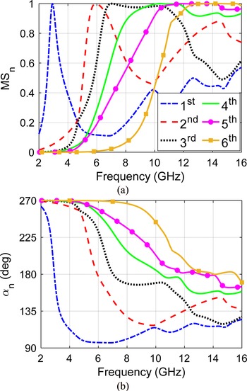
To fully grasp the performance of the proposed antenna and EBG unit cell, characteristic mode analysis (CMA) is used [Reference Chen and Wang16]. With the help of the modal currents, the role of each mode in the function of structure can be observed. CMA is the study of an eigen set of orthogonal modal currents for a conductive structure. CMA is source-independent and related to the geometry of the conductor. Two factors for better representation of CMA are modal significance (MSn) and characteristics angles (αn). MSn is equal to |1 + jλ n|−1 where λ n is an eigenvalue. At the resonance frequency is λ n = 0 and MSn = 1. For n < 0 or n > 0, the structure is in capacitance-mode or inductive-mode. Further, $\alpha _n = 180-{\rm ta}{\rm n}^{{-}1}_n$ which at eigenfrequency λ n = 0 and α n = 180. The α n indicates energy storage close to 90° or 270°.
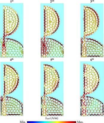
Figure 3(a) shows the modal significances of the first six resonant modes for the proposed halved UWB antenna. In the simulation, conductive surfaces in the form of PEC with zero thickness and a substrate with zero dielectric loss are used. It can be perceived that when the modal significance approaches one in this figure and the characteristic angle equals 180° in the following figure, namely Fig. 3(b), an eigenfrequency will occur. Therefore, the eigenfrequencies of the first six modes are obtained respectively at 2.93, 5.92, 7.03, 10.36, 13.12, and 14.07 GHz. The corresponding eigencurrents are plotted and also shown in Fig. 4 where current paths were marked with black arrows. Based on the state of eigencurrent in each mode, we can determine the contribution of each part of the antenna to the total performance of designed antenna, for example, at the state of 1st and 2nd modes, it is obvious that the contribution of circular patch itself outweighs the effects of ground plane. The difference between 1st and 2nd modes, however, is in the longitude of the currents which later is not in-phase with the feedline, hence 2nd mode occurs relatively at higher frequency. It is worth mentioning that the modal bandwidth for 1st and 2nd modes is much less than the modal bandwidth for higher modes. This happens due to two factors; one is the appearance of higher modes of patch and the latter is due to the huge effect of defected ground plane on the performance of antenna. This is clearly observable at eigencurrents of the 3rd and 4th modes, where two equal currents form at the edges of the ground plane thanks to the cut under feedline. The nature of 3rd and 6th modes seems to be the same and their contribution to the radiation pattern should be small; however, they have a significant role on the impedance matching. The presence of 4th and 5th modes is simply due to the existence of higher modes of the circular patch, where the antenna is expected to maintain its relatively stable pattern characteristics, albeit slightly distorted at higher frequencies.
Mode significances and characteristic angles of the first six modes of the proposed minimized UWB antenna. (a) Mode significances. (b) Characteristic angles.

Current distributions at eigenfrequency of each mode: M 1 at 2.93 GHz, M 2 at 5.92 GHz, M3 at 7.03 GHz, M 4 at 10.36 GHz, M 5 at 13.12 GHz, and M 6 at 14.07 GHz.

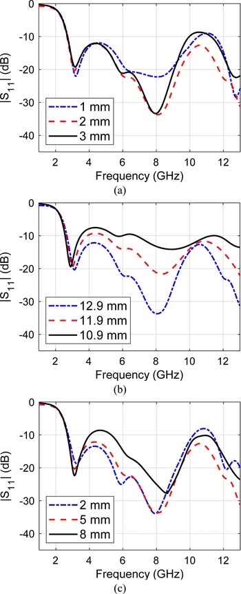
To have a better interpretation of antenna UWB performance, in Fig. 5, a parametric study has been carried out for dc, dg, and ds. Figure 5(a) shows the simulation results for different values of dc. It is observed that by etching a square under the feedline, the bandwidth and impedance matching are improved at frequencies above 9 GHz. Figures 5(b) and 5(c) depict the simulate |S 11| for dg and ds. It is clear that by shaping the ground plane, the signal reflection at the middle and lower operating band of the antenna can be minimized or improved. In fact, by manipulating the ground plane, the electromagnetic coupling between the ground plane and the radiation patch can be tuned. It should be noted that the truncated ground plane has no effect on the lower edge of the impedance bandwidth at 2.7 GHz.
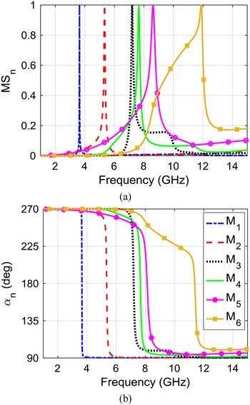
For the first six modes of the proposed open slotted meander line EBG unit cell: (a) mode significances, (b) characteristic angles.

Figure 6 shows the CMA properties of the open slotted meander line EBG unit cell. Eigenfrequency in any curve is when MSn = 1 and α n = 180. Using an optimization process, the initial dimensions of the EBG can be easily determined. In the simulation, conductive surfaces in the form of PEC with zero thickness and a substrate with zero dielectric loss are used. Within 1–15 GHz, there are six resonant frequencies at 3.64, 5.33, 7.21, 7.65, 8.62, and 11.89 GHz, respectively. The bandwidths of MS > 0.707 for all modes are very narrow. This especially can be seen in the case of the first-order mode (M 1) of the EBG and its higher mode M 2 and M 3. In addition, the slotted meander line also resonates at a narrow band in its main mode which is M 2 but this is not quite true for its upper mode, M 6, where it resonates with slightly higher bandwidth. To expand the bandwidth, it is possible to introduce lossy components to the structure of either via or slot, such as resistors. Modes M 4 and M 5 are the degenerative modes of the patch which can be found when there is no slot on the EBG patch. These modes normally overlap; however, due to the existence of the two embedded slots, this symmetry has lost and the M 4 mode is slightly shifted toward the lower frequencies.
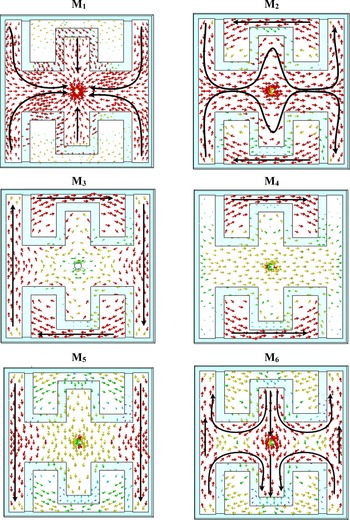
Eigencurrent distributions of the first six resonant modes of the proposed EBG at the eigenfrequency of each mode: M 1 at 3.64 GHz, M 2 at 5.33 GHz, M 3 at 7.21 GHz, M 4 at 7.65 GHz, M 5 at 8.62 GHz, and M 6 at 11.89 GHz.

To reach a better understanding, the normalized current distribution of the first six modes of this slotted EBG structure is shown in Fig. 7. For this case, we have used CST Studio Suite's field monitor to acquire the surface currents of the proposed structure with the same scale. In Fig. 7, current paths were marked with black arrows. From Fig. 7, it is obvious that in the studied frequency range, there is one mode related to the zeroth-order resonance of the EBG structure, namely M 1, which is directly associated with the existence of via in the middle of the mushroom. As seen, the current flow on the patch is directly toward the center of the EBG patch and to the location of the via, as if it plays the role of a current vacuum. M 3 is also related to M 1 with the difference that the surface currents are exiting the via toward the edges of the EBG patch, so its influence is not prevalent. The current distribution for the state of the unit cell at modes M 2 and M 6 is along the length of the slot, with the difference that for M 2, the first resonance of the slot is excited while for M 6, it is the higher resonance. As the order of the modes increases, the length of the current paths becomes shorter and current nulls appear. The wider bandwidth of M 6 also can be explained within this frame. It is important to note that modes M 4 and M 5 are the interstice modes of the square patch, and since the rotational symmetry at x and y directions is not satisfied, the current distribution at mode M 4 occurs prior to M 5.
Radiation patterns of the modal electric fields of the first six modes at: M 1 at 3.64 GHz, M 2 at 5.33 GHz, M 3 at 7.21 GHz, M 4 at 7.65 GHz, M5 at 8.62 GHz, and M 6 at 11.89 GHz.

This is mainly because only modes M 1 and M 2 are efficiently excited through coupling to the feedline. On the other hand, the modes M 3, M 4, and M 5 have equal amplitudes at some points while the characteristic angles have a near 180° phase difference, i.e. the eigencurrents weaken and nullify each other out at these areas. The effects of partial excitation of the less significant mode of M 6 are still traceable in Fig. 6, however lacks the requirement of an effective removal band due to insufficient coupling. Also, the characteristic modes of the halved patch antenna fall exactly at this range that these modes are present where the ground plane and higher order modes are both the main contributors to the performance of the antenna. Therefore, the filtering process of the unwanted frequencies of the patch at this range becomes somewhat pointless unless the structure of the ground plane is modified so that it resonates at much higher or lower frequencies.
Figure 8 shows the steps for the development of the stop bands for the suggested downsized UWB antenna. Antenna #1 has an impedance matching from 2.67 to 13 GHz. In antenna #2, the first stop band is created at 3.6 GHz by adjusting the EBG patch dimensions and via connection diameter. In antenna #3, by loading two open meander slots in the EBG square patch, an additional stop band is created at 5.33 GHz. The length of the meander open slot is about half the stop frequency wavelength. An open meander takes up less space than a straight slot. To reduce mutual coupling between meander open slots, they are positioned in the opposite directions. The designed minimized antenna has two elimination bands at 3.6 GHz (3.29–3.71 GHz, 12%) and 5.33 GHz (5.07–5.76 GHz, 12.7%). Figure 9 shows the surface current distribution. In Fig. 9(a), at 3.5 GHz, the current is concentrated around the via connection. Therefore, the little current reaches the patch for radiation. In Fig. 9(b), the current at 5.5 GHz is more intense along the edges of the loaded meander slots. In addition, by changing the length and width of the open meander slots, the location and bandwidth of the second stop band can be adjusted, respectively. In Fig. 9(c), the minimum current distribution in the EBG cell at 4 GHz is depicted. This indicates that in the working bands, the coupled EBG cell has little effect on the performance of the proposed antenna.
Design steps for two stop bands of the proposed minimized UWB antenna.

Surface current distribution at: (a) 3.5 GHz, (b) 5.5 GHz, and (c) 4 GHz.

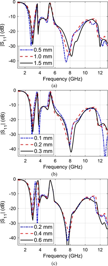
To have a better interpretation of antenna band stop performance, in Fig. 10, a parametric study has been carried out for EBG position (lg), the gap between EBG cell and feedline (g), and via diameter (dv). Figures 10(a) and 10(b), respectively, represent the simulated |S 11| results for lg and g variations. It is clear that by reducing the electromagnetic coupling between the tapered feedline and the EBG cell, the filtered bandwidth and peak value of |S 11| are reduced, while the effect of these changes on the location of stop frequencies and the selectivity of stop bands is negligible. It can be seen that changes in EBG location have less effect on stop bands. In Fig. 10(c), as the diameter of the via increases, the lower stop frequency increases, and on the other hand, the position of higher stop frequency remains almost constant. Therefore, with the dv changes, the first deletion band can be controlled.
Simulated results of suggested minimized UWB antenna with two stop bands for different: (a) lg, (b) g, (c) dv.

Fabrication and measurements
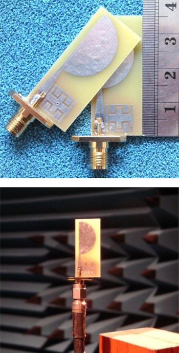
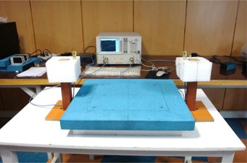
Figure 11 shows a sample of the minimized UWB antenna with two stop bands inside the anechoic chamber. In Fig. 12, the measured |S 11| shows a −10 dB impedance matching from 2.73 to 13 GHz with two stop bands with sharp selectivity at 3.51 GHz (440 MHz, 12.9%) and 5.34 GHz (770 MHz, 14.1%). However, a frequency shift is perceived in the measured response in the upper working band. As shown in Fig. 11, the antenna specification is acquired with a long 50 Ω cable and an SMA connector where the leaky current of the cable affects the measurement results. It is best to print small UWB antennas on substrates with low loss and low permittivity. Generally, the difference between the simulation and measurement results is due to the accuracy of the printing process, the accuracy of the substrate profile, the measurement outside the chamber, the wide simulation range, and the soldering of the connector. Figure 13 shows the S 21 measurement setup. The S 21 was measured through connecting two similar antennas to a PNA E83363C. PNA is calibrated on the antenna ports. A 5 cm-thick absorber was used to reduce the effects of outdoor space between the two antennas. The distance between the antennas is 60 cm, which is almost six times the smallest operating frequency. Figure 14 shows the measured transmission parameters for the suggested antenna in both face-to-face and side-to-side positions. In Fig. 14(a), a large drop is spotted in the stop bands and little change outside of it. In Fig. 14(b), the phase is linear along the working band except in the stop bands. In Fig. 14(c), group delay is almost unchanged except in stop bands. This indicates that the suggested minimized UWB antenna is capable of sending and receiving short pulses without distortion.
Prototype of suggested minimized UWB antenna with two removal bands.

Simulation and measurement results |S 11| of suggested antenna.

Measurement of S 21 for the suggested antenna.

Measured transmission parameters for the suggested antenna: (a) |S 21|, (b) phase, (c) group delay.

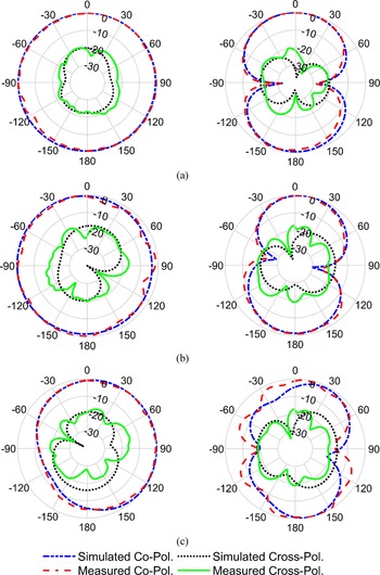
Figure 15 shows the radiation pattern in the principal planes. As the frequency increases, the antenna pattern becomes slightly more oriented due to the asymmetry of the antenna. At 12 GHz, in Fig. 15(c), there is eventually a greater difference between the measurement and simulation results. In fact, the effects of cable, connector, and soldering on the ground plane of the small antenna at high frequencies are greater. Also, as the frequency increases, the electrical length of the ground plane increases, which makes the antenna pattern more inclined toward the x-axis. Compared to the reference antenna (#1 in Fig. 2), the cross-polarization level increases with the increase of frequency are due to the symmetry of the current on the ground plane of the reference antenna along the x-axis, and also the current being out of phase which, in turn, cancel each other out. By shrinking the reference antenna, one side of these currents on the ground plane is removed and the other side increases cross-polarization. To reduce cross-polarization at high frequencies in the minimized antenna, it is recommended to reduce the width of the ground plane.
Radiation patterns in xz (left) and yz (right) planes at: (a) 3 GHz, (b) 7 GHz, and (c) 12 GHz.

Figure 16 shows the measured peak gain for the suggested antenna. Maximum and average gains are 2.5 and 1.95 dBi, respectively. Compared to the reference antenna (#1 in Fig. 2), the gain of the reduced antenna is lower due to the reduction of the antenna dimensions. In addition, at higher frequencies, the gain of two antennas is similar, owing to the pattern of the reduced antenna which is more directional. The simulated total efficiency of the suggested antenna is presented in Fig. 17 that is higher than 78% at all the operating band. The antenna total efficiency is expressed as η t = η i × η r [Reference Huang, Chen, Liu, Nakano, Qing and Zwick17]. The η i indicates the antenna impedance mismatch, which is equal to η i = 1 − |S 11|2 and η r is the radiant efficiency of the antenna, which is equal to the ratio of the total radiated power to the total power accepted by the antenna.
Measured gain for the suggested antenna.

Simulated efficiency for the suggested antenna.

To prove the improvement of the present design over the state of the art, a comparison with some of the latest designs of band stops UWB antennas by mushroom-type EBG cells is listed in Table 1. It can be seen that compared to [Reference Amani and Jafargholi8–Reference Kapure, Bhavarthe and Rathod15], the size of the proposed antenna is almost halved. Compared to [Reference Abdalla, Al-Mohamadi and Mohamed10] and [Reference Modak, Khan and Laskar13, Reference Trimukhe and Hogade14], fewer EBGs have been used to create two stop bands. Furthermore, compared to [Reference Amani and Jafargholi8] and [Reference Ghahremani, Ghobadi, Nourinia, Ellis, Alizadeh and Mohammadi9], the proposed patch area of EBG is smaller. The fewer number of the employed EBG cells and the lower the amount of EBG area is, the less impact the EBG has on the antenna radiation pattern and the easier it is to match the impedance. Compared to [Reference Thakur, Jaglan and Gupta11] and [Reference Trimukhe and Hogade14, Reference Kapure, Bhavarthe and Rathod15], the number of vias per EBG cells is fewer, which leads to less costly construction and less complexity. In addition, the selectivity of the stop bands is higher compared to [Reference Ghahremani, Ghobadi, Nourinia, Ellis, Alizadeh and Mohammadi9], which is due to the squareness of the EBG patch, the location of the EBG cell, and the proposed slits structure. In the long run, the proposed open meander slit structure allows easier reconfigurability and tunability compared to [Reference Amani and Jafargholi8–Reference Modak, Khan and Laskar13]. Finally, although the EBG presented in [Reference Thakur, Jaglan and Gupta11] has three removal bands by one cell, the proposed EBG has a lower number of vias, a simpler structure, and no slot at the ground plane of the EBG cell.
Comparison of the proposed antenna with other band stops UWB antennas by mushroom type EBG cells

l, Lowest frequency of the operating band; h, substrate thickness, f c, center frequencies of notches; antenna bandwidth: |S 11|<−10 dB.
This antenna can be used in many portable consumer electronics for high speed and short-range communications such as personal computers, printers, scanners, speakers, wireless USB hub, video recorder, automotive, and home networks. Also, small UWB antennas can be used in wireless sensor networks for environmental monitoring, traffic control, and healthcare. Another application of UWB antenna is in location and ranging awareness, i.e. for accurate positioning inside large buildings or commercial stores. To increase the performance of UWB antennas, the use of several elements in the form of multiple-input and multiple-output (MIMO) is recommended, which can also be used in 5G systems. Therefore, it is more appropriate to use a single UWB element with minimized layout area.
Conclusion
In this paper, a small UWB antenna with two stop bands, wide bandwidth, simple structure, and stable specifications for radiation pattern, gain, group delay, and transmission function in the working frequency range was presented. Two stop bands with sharp selectivity were created by coupling a compact EBG cell loaded with open meander slots to the feedline. The designed compact slotted EBG cell had little effect on the characteristics of the UWB antenna and is easy to switch. The proposed EBG cell was examined by the CMA, which helps to grasp the behavior of the band stops. Halving and modifying the reference antenna reduces the size of the designed antenna by 48%. Practical results were done and showed a −10 dB impedance matching from 2.73 to 13 GHz with stop bands at 3.51 GHz (3.20–3.64 GHz, 12.9%) and 5.34 GHz (5.08–5.85 GHz, 14.1%) to eliminate WiMAX, C-band communications, and WLAN. The suggested small UWB antenna with two stop bands was considered to be suitable for compact portable integrated systems such as chip transceivers and medical imaging.
 Farzad Alizadeh obtained his bachelor's degree in Communication Engineering in 2012 from the University of Tabriz. He obtained his M.Sc. degree in RF and Microwave Engineering at Urmia University in 2014. His research interests include electrically small antennas, multi-functional antennas, metamaterial designs, and their applications.
 Changiz Ghobadi obtained his B.Sc. degree in Electrical Engineering and M.Sc. degrees in Electrical Engineering Telecommunication from Isfahan University of Technology, Isfahan, Iran, and Ph.D. degree in Electrical Telecommunication from the University of Bath, Bath, UK, in 1998. He is currently a Professor in the Faculty of Engineering of Urmia University, Urmia, Iran. He established Northwest Antenna and Microwave Research Laboratory (NAMRL) at the Urmia University with the focus on microwave, antennas, and propagation devices characterization, design, and fabrication. He has supervised and administered more than 130 M.Sc. and 32 Ph.D. students and their thesis. He has authored and coauthored over 320 scientific publications including accredited journals and conferences. His papers have been cited over 4500 times. He has been included in the Top One Percent of the World's Scientists and Academics according to Thomson Reuters' list in 2017 and 2020. His primary research interests are in antenna, radar, and adaptive filters.
 Javad Nourinia obtained his B.Sc. degree in Electrical and Electronic Engineering from Shiraz University, M.Sc. degree in Electrical and Telecommunication Engineering from Iran University of Science and Technology, and Ph.D. degree in Electrical and Telecommunication from the University of Science and Technology, Tehran, Iran, in 2000. He was on the Faculty of the Department of Electrical Engineering as an Assistant Professor from 2002 to 2006 and an Associate Professor from 2007 to 2012, and has been a Full Professor since 2013. He has been the Head of the Faculty Engineering Department from 2013 to 2017 and a Distinguished Professor at Urmia University. He has coauthored over 350 scientific publications. His papers have been cited over 4700 times. He has been included in the Top One Percent of the World's Scientists and Academics according to Thomson Reuters’ list since 2016. His research interests include small antennas, filters, MIMO antennas, periodic structures, and measurement.