I. INTRODUCTION
Nanocrystalline (nc) metals and ceramics exhibit outstanding mechanical characteristics that attracted great interest currently.Reference Liu, Zhou, Shen and Hui1–Reference Koch10 However, in spite of their superior mechanical properties, such as superstrength, superhardness, and good wear resistance, nc solids typically display a brittle behavior, low tensile ductility, and low fracture toughness, which severely limit their practical applications.Reference Khan, Farrok and Takacs11–Reference Koch, Ovid’ko, Seal and Veprek15 Experimental studies find that some nc metals with the face-centered-cubic lattice show a ductile-to-brittle transition with the decreasing grain size, which is different to the conventional coarse-grained materials. Nevertheless, some other nc materials, such as nc ceramics, exhibit the enhancement of fracture toughness compared with those of their microcrystalline counterparts. The difference in fracture behavior lies in their different structural features, so it arouses strong interest to explore special toughening mechanisms for nc materials. Some specific deformation modes, such as diffusion-assisted creep, dislocation slip, twinning, shear banding, grain boundary sliding, grain rotation, etc., have been theoretically described as the specific toughening mechanisms in nc materials.Reference Bobylev, Mukherjee, Ovid’ko and Sheinerman16–Reference Ovid’ko, Skiba and Mukherjee20 In particular, following the experimental data, computer simulations, and theoretical models, stress-driven grain boundaries migration is treated as rotational deformation mechanism effectively performed in nc materials.Reference Demkowicz, Argon, Farkas and Frary21–Reference Ovid’ko and Sheinerman23 The special rotational deformation is formed in nanograin through the formation of immobile wedge disclination quadrupole at nanograin boundary junctions, and it is characterized by a gradual increase of strengths of the immobile disclinations during their formation process conducted by grain boundary sliding and diffusion. A wedge disclination represents a rotational line defect located at a triple junction of grain boundaries and characterized by disclination strength.Reference Fang, Liu, Jiang and Li24, Reference Wu, Zhou and Nazarov25
In general, there will be ultrafine defects in nc materials during the manufacturing process, such as cracks, nanoholes, dislocations, etc. Therefore, the understanding of the interaction between these microdefects is of vital importance. The stress intensity factor (SIF) of the crack tip is a common and effective way to investigate the fracture behavior of nc materials. When the SIF of the crack tip becomes large enough, the crack can induce plastic shear through the emitting of edge dislocations from the crack tip, which will cause the crack blunting and then hinder the crack propagation and finally improve the toughness of nc materials. Most of previous research, including experimental study and theoretical derivation, are focus on the contribution of the rotational deformation to the toughening of nc materials but seldom to quantitatively investigate the effect of the special rotational deformation on the emission of lattice dislocations from the crack tips. Fang et al.Reference Fang, Feng, Liu, Lin and Zhang26 have theoretically described the effect of special rotational deformation on the dislocation emission from a line crack tip in deformed nc materials. However, a real crack in a material is always of finite length, and the radius of curvature of the crack tip is never small enough to be zero, having a curvature radius of several Burgers vectors due to the removal of atoms via diffusion or mechanical and chemical erosions. On the other hand, the emission of dislocations from the crack tip will result in crack blunting, and then, the stresses near the crack tip zone will be relaxed. Hence, crack blunting plays an important role in the fracture process, so it is important to investigate the interaction between dislocations and the blunt crack.Reference Huang and Li27 Fischer and BeltzReference Fischer and Beltz28 analyzed the effect of crack blunting on competition between dislocation nucleation and cleavage. Li et al.Reference Li, Lia and Sun29 investigated the shielding effect of dislocation near elliptically blunted crack. Huang et al.Reference Huang, Rivera Díaz del Castillo and Li30 studied the dislocation emission criterion from a crack tip. Ovid’ko and SheinermanReference Ovid’ko and Sheinerman31, Reference Ovid’ko and Sheinerman32 investigated the combined effect of grain boundaries and blunting of cracks on the fracture toughness of nc materials and found that nc metals exhibit a ductile-to-brittle transition with decrease grain size. After that, they proposed a theoretical model to describe generation and growth of nanoscale cracks near tips of blunt crack in nc solids and discussed the effects on toughness of nc solids. In this paper, a theoretical model is established to discuss the interaction between a wedge disclination quadrupole produced by the special rotational deformation and a semielliptical blunt crack tip in deformed nc materials under mode I and mode II loads, and a comparison with the sharp crack behavior is also presented.
II. PROBLEM STATEMENT AND THE BASIC EQUATIONS
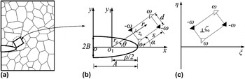
Let us consider a deformed nc solid consisting of nanoscale grains divided by grain boundaries and containing a long slit with blunted head. The solid is assumed to be elastic and isotropic, whose shear modulus is μ and Poisson’s ratio is ν and is subjected to remote mode I loadings and mode II loadings. A two-dimensional (2D) section of a typical fragment of the solid is schematically shown in Fig. 1(a), and the defect structure is assumed to be the same along the coordinate axis z perpendicular to the xyplane. Therefore, for simplicity, we restrict our consideration to a 2D problem. Certainly, the 2D description reflects the key aspects of the problem. The length of slit is longer than the grain size, so it can be treated as a semielliptical blunt crack.
The special rotational deformation in a plastic deformed nc solid containing a semielliptic blunt crack: (a) general view, (b) the magnified inset highlights the special rotational deformation near the blunt crack tip, and (c) ζ-plane after conformal mapping.

Introducing a Cartesian system (x, y) shown in Fig. 1(b), a free surface x = 0 contains the semielliptical blunt crack whose center is located at the origin o with the semimajor axis length A and the semiminor axis length B. Then, let us introduce a polar coordinate system (r, θ) with origin at o 1 that ρ/2 behind the notch root, and the parameter ρ = B 2/A is the radius of curvature of the elliptically blunted crack tip. A wedge disclination quadrupole, representing the special rotational deformation, consists of two positive disclinations with strength ω at z 1 = (A − ρ/2) + r 1 ${\rm{e}}^{{\rm{i\theta }}_{\rm{1}} } $ and z 3 = z 1 + seiα + dei(α + π/2) and two negative disclinations with the same strength at z 2 = z 1 + seiα and z 4 = z 1 + dei(α + π/2), respectively. Here, s and d represent the quadrupole arms (the grain size); α represents the angle between the crack plane and one of the quadrupole arms s.
For the plane strain problem, stress fields can be expressed in terms of two Muskhelishvili’s complex potentials ϕ(z) and ψ(z)Reference Muskhelishvili33:
 $${\rm{\sigma }}_{xx} \, + \,{\rm{\sigma }}_{yy} \, = \,2\left[ {\varphi \prime(z)\, + \,\overline {\varphi \prime(z)} } \right]\quad,$$
 $$<![CDATA[$${\rm{\sigma }}_{yy} \, - \,{\rm{i\sigma }}_{xy} \, = \,\varphi \prime(z)\, + \,\overline {\varphi \prime(z)} \, + \,z\overline {\varphi \Prime(z)} \, + \,\overline {{\rm{\psi \prime}}(z)} \quad,$$
with z = x + iy. The superposed bar denotes a complex conjugate, and the prime denotes differentiation with respect to the argument z. And the stress components σxx, σyy, and σxycan be written as:
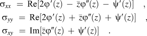 $$<![CDATA[$$\matrix{ {{\rm{\sigma }}_{xx} \,\, = \,{\mathop{\rm Re}\nolimits} [2\varphi \prime(z)\, - \,\bar z\varphi \Prime(z)\, - \,{\rm{\psi \prime}}(z)]\quad,} \cr {{\rm{\sigma }}_{yy} \, & \, = \,{\mathop{\rm Re}\nolimits} [2\varphi \prime(z)\, + \,\bar z\varphi \Prime(z)\, + \,{\rm{\psi \prime}}(z)]\quad,} \cr {{\rm{\sigma }}_{xy} \, & & \, = \,{\mathop{\rm Im}\nolimits} [\bar z\varphi \Prime(z)\, + \,{\rm{\psi \prime}}(z)]\quad.} \cr } $$
Introducing the following mapping functionReference Huang and Li27:
 $$z\, = \,{\rm{\omega }}({\rm{\zeta }})\, = \,{{A\sqrt {{\rm{\zeta }}^2 \, + \,A^2 } \, + \,B\sqrt {{\rm{\zeta }}^2 \, + A^2 \, - \,C^4 P^2 } } \over {C^2 P}}\quad,$$
with ζ = η + iξ,  $P\, = \,{A \over {A^2 - B^2 }}$, and
 $C\, = \,\sqrt {A^2 - B^2 } $, which maps the surface of blunt crack in the z-plane into half-space in the ζ-plane (ξ > 0), as shown in Fig. 1(c).
With the mapping Eq. (4), Eqs. (1) and (2) can be rewritten in the ζ-plane as follows:
 $${\rm{\sigma }}_{xx} \, + \,{\rm{\sigma }}_{yy} \, = \,2\left[ {\Phi ({\rm{\zeta }})\, + \,\overline {\Phi ({\rm{\zeta }})} } \right]\quad,$$
 $${\rm{\sigma }}_{yy} \, - {\rm{i\sigma }}_{xy} \, = \,\Phi ({\rm{\zeta }})\, + \,\overline {\Phi ({\rm{\zeta }})} \, + \,{{{\rm{\omega }}({\rm{\zeta }})} \over {\overline {{\rm{\omega \prime}}({\rm{\zeta }})} }}\overline {\Phi \prime({\rm{\zeta }})} \, + \,\overline {\Psi ({\rm{\zeta }})}\quad ,$$
where Φ(ζ) = ϕ′(ζ)/ω′(ζ),  $\Phi \prime({\rm{\zeta }}) = {{\varphi \Prime({\rm{\zeta }}){\rm{\omega \prime}}({\rm{\zeta }}) \,-\, \varphi \prime({\rm{\zeta }}){\rm{\omega \Prime}}({\rm{\zeta }})} \over {[{\rm{\omega \prime}}({\rm{\zeta }})]^2 }}$, and Ψ(ζ) = ψ′(ζ)/ω′(ζ).
The boundary condition of the crack for the problem can be written as:
 $${\rm{\sigma }}_{yy} (t)\, - \,{\rm{i\sigma }}_{xy} (t)\, = \,0,\,\,\,\,t\,\, \in \,\,{\rm{blunt}}{\kern 1pt} {\kern 1pt} {\rm{crack}}{\kern 1pt} {\kern 1pt} {\rm{surface}}\quad{\rm{.}}$$
Referring to the work of Fang et al.Reference Fang, Liu, Jiang and Li24, Reference Liu and Fang34 and Song et al.,Reference Song, Fang and Liu35 and using the superposition principle, the complex function ϕw(ζ) and ψw(ζ) can be obtained as:
 $$\varphi _w ({\rm{\zeta }})\, = \,{{D{\rm{\omega }}} \over 2}\mathop\sum\limits_{k\, = \,1}^4 {( - 1)^k [ {{{\bar \omega }}({\rm{\zeta }})\ln ( { - {\rm{\zeta }} - \overline {{\rm{\zeta }}_k } } ) - z_k \ln ( { - {\rm{\zeta }} - \overline {{\rm{\zeta }}_k } } ) - H_k ({\rm{\zeta }} - {\rm{\zeta }}_k )\ln ({\rm{\zeta }} - {\rm{\zeta }}_k )} ]\quad,} $$
 $$\eqalignb{{\rm{\psi }}_w ({\rm{\zeta }})\, = \,{{A\sqrt {{\rm{\zeta }}^2 \, + \,A^2 } + \,B\sqrt {{\rm{\zeta }}^2 \, + \,A^2 - C^4 P^2 } } \over {{{A{\rm{\zeta }}} \over {\sqrt {{\rm{\zeta }}^2 + A^2 } }} + {{B{\rm{\zeta }}} \over {\sqrt {{\rm{\zeta }}^2 + A^2 - C^4 P^2 } }}}}{{D{\rm{\omega }}} \over 2}\mathop\sum\limits_{k = 1}^4 {( - 1)^k [ {{{\bar \omega '}}({\rm{\zeta }})\ln ( { - {\rm{\zeta }} - \overline {{\rm{\zeta }}_k } }) - {{{{\bar \omega }}({\rm{\zeta }})} \over { - {\rm{\zeta }} - \overline {{\rm{\zeta }}_k } }} - H_k \ln ({\rm{\zeta }} - {\rm{\zeta }}_k ) - H_k { + {{z_k } \over { - {\rm{\zeta }} - \overline {{\rm{\zeta }}_k } }}} ] + {{D{\rm{\omega }}} \over 2}\sum\limits_{k = 1}^4 {( - 1)^k [ {{\rm{\omega }}({\rm{\zeta }})\ln ({\rm{\zeta }} - {\rm{\zeta }}_k ) + \overline {z_k } \ln ({\rm{\zeta }} - {\rm{\zeta }}_k ) + \overline {H_k } ( { - {\rm{\zeta }} - \overline {{\rm{\zeta }}_k } })\ln ( { - {\rm{\zeta }} - \overline {{\rm{\zeta }}_k } } )} ]\,\,} \cr , \cr} $$
where D = μ/2π(1 − v), 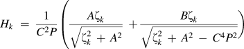 $H_k \;= \;{1 \over {C^2 P}}\left( {{{A{\rm{\zeta }}_k } \over {\sqrt {{\rm{\zeta }}_k^2\, +\, A^2 } }} \;+ {{B{\rm{\zeta }}_k } \over {\sqrt {{\rm{\zeta }}_k^2 \,+\, A^2\, -\, C^4 P^2 } }}} \right )$, and zk = ω(ζk).
III. THE EMITTING OF LATTICE DISLOCATIONS FROM BLUNT CRACK TIP
Let us consider the emitting of lattice dislocation form the blunt crack tip. For simplicity, we just focus on the situation that the dislocations are of edge character and their Burgers vectors lie along the slip plane making an angle θ0 with x axis. Supposing that the first dislocation is located at z 0 = (A − ρ/2) + r 0 ${\rm{e}}^{{\rm{i\theta }}_0 } $, the elastic fields of edge dislocation can be calculated by the complex potential ϕe(ζ) and ψe(ζ)Reference Fang, Song and Liu36:
 $$\varphi _e ({\rm{\zeta }})\, = \,\varphi _{e0} ({\rm{\zeta }})\, + \,\varphi _e^* ({\rm{\zeta }})\quad,$$
 $${\rm{\psi }}_e ({\rm{\zeta }})\, = \,{\rm{\psi }}_{e0} ({\rm{\zeta }})\, + \,{\rm{\psi }}_e^* ({\rm{\zeta }})\quad,$$
where ϕe(ζ) = wln(ζ − ζ0),  ${\rm{\psi }}_{e0} ({\rm{\zeta }})\, = \,\bar w\ln ({\rm{\zeta }} - {\rm{\zeta }}_0 ) - {{w{\kern 1pt} {\kern 1pt} {\kern 1pt} {\kern 1pt} \overline {{\rm{\omega }}({\rm{\zeta }}_0 )} } \over {H_0 ({\rm{\zeta }} \,-\, {\rm{\zeta }}_0 )}}$,
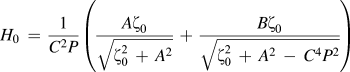 $H_0 \, = \,{1 \over {C^2 P}}\left( {{{A{\rm{\zeta }}_0 } \over {\sqrt {{\rm{\zeta }}_{\rm{0}}^{\rm{2}} \, + \,A^2 } }}\, + \,{{B{\rm{\zeta }}_0 } \over {\sqrt {{\rm{\zeta }}_{\rm{0}}^{\rm{2}} \, + \,A^2 \, - \,C^4 P^2 } }}} \right)$, and
 $w\, = \,{{\rm{\mu }} \over {4{\rm{\pi }}(1 - \nu )}}(b_y - {\rm{i}}b_x )$.
Referring to the work of Fang et al.,Reference Fang, Song and Liu36 we can obtain:
 $$\varphi _e ({\rm{\zeta }})\, = \,w\ln ({\rm{\zeta }} - {\rm{\zeta }}_0 )\, - \,{{\bar H\bar w} \over { - {\rm{\zeta }} - \overline {{\rm{\zeta }}_0 } }}\, - \,w\ln \left( { - {\rm{\zeta }} - \overline {{\rm{\zeta }}_0 } } \right)\quad,$$
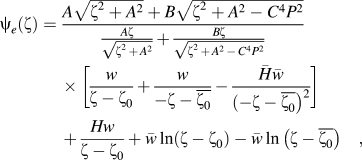 $$\eqalignb{ {\rm{\psi }}_e ({\rm{\zeta }}) = \,{{A\sqrt {{\rm{\zeta }}^2 + A^2 } + B\sqrt {{\rm{\zeta }}^2 + A^2 - C^4 P^2 } } \over {{{A{\rm{\zeta }}} \over {\sqrt {{\rm{\zeta }}^2\, +\, A^2 } }} + {{B{\rm{\zeta }}} \over {\sqrt {{\rm{\zeta }}^2 \,+\, A^2 \,-\, C^4 P^2 } }}}} [ {{w \over {{\rm{\zeta }} - {\rm{\zeta }}_0 }} + {w \over { - {\rm{\zeta }} - \overline {{\rm{\zeta }}_0 } }} - {{\bar H\bar w} \over { ( { - {\rm{\zeta }} - \overline {{\rm{\zeta }}_0 } } )^2 }}} ]\, + {{Hw} \over {{\rm{\zeta }} - {\rm{\zeta }}_0 }} + \bar w\ln ({\rm{\zeta }} - {\rm{\zeta }}_0 ) - \bar w\ln ({\rm{\zeta }} - \overline {{\rm{\zeta }}_0 } )\quad, } $$
where  $H\, = \, - \,{{A\sqrt {{\rm{\zeta }}_0 ^2 \,+\, A^2 } \, + \,B\sqrt {{\rm{\zeta }}_0 ^2 \,+ \,A^2 \,- \,C^4 P^2 } } \over {{{A{\rm{\zeta }}_0 } \over {\sqrt {{\rm{\zeta }}_0 ^2 \,+ \,A^2 } }}\, + \,{{B{\rm{\zeta }}_0 } \over {\sqrt {{\rm{\zeta }}_0 ^2 \,+ \,A^2 \,- \,C^4 P^2 } }}}}\, - \,{{A\sqrt {\overline {{\rm{\zeta }}_0 } ^2 \, + \,\,A^2 } \, + \,B\sqrt {\overline {{\rm{\zeta }}_0 } ^2 + \,A^2 \, - \,C^4 P^2 } } \over {{{A{\rm{\zeta }}_0 } \over {\sqrt {{\rm{\zeta }}_0^2 \, \,+ \,A^2 } }}\, + \,{{B{\rm{\zeta }}_0 } \over {\sqrt {{\rm{\zeta }}_0^2 \, + \,A^2 \, - \,C^4 P^2 } }}}}$.
Then, the force acting on the edge dislocation consists of three parts: (i) the image force, (ii) the force produced by the wedge disclination quadrupole, and (iii) the external force.
First, the image force can be expressed by using the Peach–Koehler formulaReference Fang, Liu, Jin and Wen37, Reference Hirth and Lothe38:
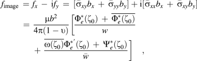 $$f_{{\rm{image}}} \, = \,\,f_x \, - \,{\rm{i}}f_y \, = \, [ {{\rm{\mathord{\buildrel{\lower3pt\hbox{$\scriptscriptstyle\frown$}}\over \sigma } }}_{xy} b_x \, + \,{\rm{\mathord{\buildrel{\lower3pt\hbox{$\scriptscriptstyle\frown$}}\over \sigma } }}_{yy} b_y } ]+ {\rm{i}} [ {{\rm{\mathord{\buildrel{\lower3pt\hbox{$\scriptscriptstyle\frown$}}\over \sigma } }}_{xx} b_x \, + \,{\rm{\mathord{\buildrel{\lower3pt\hbox{$\scriptscriptstyle\frown$}}\over \sigma } }}_{xy} b_y } ]\, = \,{{{\rm{\mu }}b^2 } \over {{\rm{4\pi }} ( {1- \upsilon } )}} [ {{{\Phi _e^* ({\rm{\zeta }}_0 )\, + \,\overline {\Phi _e^* ({\rm{\zeta }}_0 )} } \over w}\, + \,{{\overline {{\rm{\omega }}({\rm{\zeta }}_0 )} \Phi _e^{*\prime } ({\rm{\zeta }}_0 )\, + \,\Psi _e^* ({\rm{\zeta }}_0 )} \over {\bar w}} ]\quad,$$
where  ${\rm{\mathord{\buildrel{\lower3pt\hbox{$\scriptscriptstyle\frown$}}\over \sigma } }}_{xx} $,
 ${\rm{\mathord{\buildrel{\lower3pt\hbox{$\scriptscriptstyle\frown$}}\over \sigma } }}_{yy} $, and
 ${\rm{\mathord{\buildrel{\lower3pt\hbox{$\scriptscriptstyle\frown$}}\over \sigma } }}_{xy} $ are the components of the perturbation stress,
 $\Phi _e^ * ({\rm{\zeta }}_0 )\, = \,\varphi _e^{ * \prime } ({\rm{\zeta }}_0 )/{\rm{\omega \prime}}({\rm{\zeta }}_0 )$,
 $\Phi _e^{ * \prime } ({\rm{\zeta }}_0 )\, = {{\varphi _e^{ * \Prime } ({\rm{\zeta }}_0 ){\rm{\omega \prime}}({\rm{\zeta }}_0 ) \,- \,\varphi _e^ * ({\rm{\zeta }}_0 ){{\omega \Prime}}({\rm{\zeta }}_0 )} \over {[{\rm{\omega \prime}}({\rm{\zeta }}_0 )]^3 }}$, and
 $\Psi _e^ * ({\rm{\zeta }}_0 )\, = \,{\rm{\psi }}_e^{ * \prime } ({\rm{\zeta }}_0 )/{\rm{\omega \prime}}({\rm{\zeta }}_0 )$.
Second, the force produced by disclination quadrupole on dislocation can be denoted as:
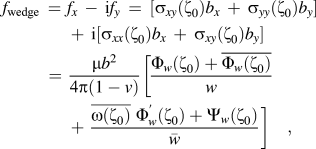 $$\eqalignb{ f_{{\rm{wedge}}} \, = \,\,f_x \, - \,{\rm{i}}f_y \, = \, [ {{\rm{\sigma }}_{xy} ({\rm{\zeta }}_0 )b_x \, + \,{\rm{\sigma }}_{yy} ({\rm{\zeta }}_0 )b_y } ]\, + \,{\rm{i}} [ {{\rm{\sigma }}_{xx} ({\rm{\zeta }}_0 )b_x \, + \,{\rm{\sigma }}_{xy} ({\rm{\zeta }}_0 )b_y } ] \cr {\kern 1pt} {\kern 1pt} {\kern 1pt} {\kern 1pt} {\kern 1pt} {\kern 1pt} {\kern 1pt} {\kern 1pt} {\kern 1pt} {\kern 1pt} {\kern 1pt} {\kern 1pt} {\kern 1pt} {\kern 1pt} {\kern 1pt} {\kern 1pt} {\kern 1pt} {\kern 1pt} {\kern 1pt} {\kern 1pt} {\kern 1pt} \,{\kern 1pt} {\kern 1pt} {\kern 1pt} \!\!\!\!\!\!\!\!= \,{{{\rm{\mu }}b^2 } \over {{\rm{4\pi }} ( {1 - v } )}} [ {{{\Phi _w ({\rm{\zeta }}_0 ) + \overline {\Phi _w ({\rm{\zeta }}_0 )} } \over w}\, + \,{{\overline {{\rm{\omega }}({\rm{\zeta }}_0 )} {\kern 1pt} {\kern 1pt} {\kern 1pt} \Phi _w^\prime ({\rm{\zeta }}_0 ) + \Psi _w ({\rm{\zeta }}_0 )} \over {\bar w}} ]\quad, \cr} $$
where σxx, σyy, and σxy are the components of the stress field produced by the wedge disclination quadrupole,  $\Phi _{\rm{\omega }} ({\rm{\zeta }}_0 )\, = \,\varphi{ \prime}_{\rm{\omega }}({\rm{\zeta }}_0 )/{\rm{\omega \prime}}({\rm{\zeta }}_0 )$,
 $\Phi {\prime}_{\rm{\omega }} ({\rm{\zeta }}_0 )\, = {{\varphi {\Prime}_{\rm{\omega }}({\rm{\zeta }}_0 ){\rm{\omega \prime}}({\rm{\zeta }}_0 ) - \varphi {\prime}_{\rm{\omega }} ({\rm{\zeta }}_0 ){\rm{\omega \Prime}}({\rm{\zeta }}_0 )} \over {[{\rm{\omega \prime}}({\rm{\zeta }}_0 )]^3 }}$, and
 $\Psi _{\rm{\omega }} ({\rm{\zeta }}_0 ) = {\rm{\psi{\prime} }}_{\rm{\omega }} ({\rm{\zeta }}_0 )/{\rm{\omega \prime(\zeta }}_0 )$.
Finally, the external force acting on the edge dislocation can be written as:
 $$f_\Gamma = b{\rm{\sigma }}_{r{\rm{\theta }}} \quad,$$
where σrθ = (σy − σx)sinθ cosθ + σxy (cos2θ − sin2θ) is the in-plane shear stress due to the applied mode I and remote mode II loadings.
In addition, considering the first terms of series expansion, IrwinReference Irwin39 had obtained his well-known equations of the stress fields near a sharp crack. Considering the case of a slender elliptical notch, solutions similar to the Irwin’s equations have been derived by Creager and ParisReference Creager and Paris40:
 $$\left\{ \matrix{ {\rm{\sigma }}_x \hfill \cr {\rm{\sigma }}_y \hfill \cr {\rm{\sigma }}_{xy} \hfill \cr} \right\}\, = \,{{K_{\rm{I}}^{{\rm{app}}} } \over {\sqrt {2{\rm{\pi }}r} }}\left\{ \matrix{ \cos {{\rm{\theta }} \over 2}\, - \,{1 \over 2}\sin {\rm{\theta }}\sin {{3{\rm{\theta }}} \over 2}\, - \,{{\rm{\rho }} \over {2r}}\cos {{3{\rm{\theta }}} \over 2} \hfill \cr \cos {{\rm{\theta }} \over 2}\, + \,{1 \over 2}\sin {\rm{\theta }}\sin {{3{\rm{\theta }}} \over 2}\, + \,{{\rm{\rho }} \over {2r}}\cos {{3{\rm{\theta }}} \over 2} \hfill \cr {\kern 1pt} {\kern 1pt} {\kern 1pt} {\kern 1pt} {\kern 1pt} {1 \over 2}\sin {\rm{\theta }}\cos {{3{\rm{\theta }}} \over 2}\, - \,{{\rm{\rho }} \over {2r}}\sin {{3{\rm{\theta }}} \over 2} \hfill \cr} \right\}\, + \,{{K_{{\rm{II}}}^{{\rm{app}}} } \over {\sqrt {2{\rm{\pi }}r} }}\left\{ \matrix{ - 2\sin {{\rm{\theta }} \over 2}\, - \,{1 \over 2}\sin {\rm{\theta }}\cos {{3{\rm{\theta }}} \over 2}\, + \,{{\rm{\rho }} \over {2r}}\sin {{3{\rm{\theta }}} \over 2} \hfill \cr {\kern 1pt} {\kern 1pt} {\kern 1pt} {\kern 1pt} {\kern 1pt} {\kern 1pt} {\kern 1pt} {\kern 1pt} {\kern 1pt} {\kern 1pt} {\kern 1pt} {\kern 1pt} {\kern 1pt} {\kern 1pt} {1 \over 2}\sin {\rm{\theta }}\cos {{3{\rm{\theta }}} \over 2}\, - \,{{\rm{\rho }} \over {2r}}\sin {{3{\rm{\theta }}} \over 2} \hfill \cr {\kern 1pt} {\kern 1pt} {\kern 1pt} {\kern 1pt} \cos {{\rm{\theta }} \over 2} - {1 \over 2}\sin {\rm{\theta }}\sin {{3{\rm{\theta }}} \over 2}\, - \,{{\rm{\rho }} \over {2r}}\cos {{3{\rm{\theta }}} \over 2} \hfill \cr} \right\}\quad,$$
where  $K_{\rm{I}}^{{\rm{app}}} $ and
 $K_{{\rm{II}}}^{{\rm{app}}} $are the generalized mode I and mode II SIFs produced by remote loadings, assuming that the notch is replaced by a sharp crack with a translation of the crack tip on its curvature center.
The substitution of Eq. (17) to Eq. (16) yields:
 $$f_\Gamma \, = \,{b \over {\sqrt {2{\rm{\pi }}r} }}\left( {l_1 K_{\rm{I}}^{{\rm{app}}} \, + \,l_2 K_{{\rm{II}}}^{{\rm{app}}} } \right)\quad,$$
where  $l_1 \, = \,{1 \over 2}\sin {{\rm{\theta }} \over 2}\left( {1\, + \cos {\rm{\theta }}\, + \,{{\rm{\rho }} \over r}} \right)$ and
 $l_2 \, = \,\cos {{3{\rm{\theta }}} \over 2}\, + \,{1 \over 2}\sin {\rm{\theta }}\sin {{\rm{\theta }} \over 2}\, - \,{{\rm{\rho }} \over {2r}}\cos {{\rm{\theta }} \over 2}$.
Therefore, the dislocation force acting on the edge dislocation can be written as:
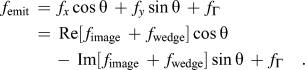 $$f_{{\rm{emit}}} \, = \,f_x \cos {\rm{\theta }}\, + \,f_y \sin {\rm{\theta }}\, + \,f_\Gamma \, \cr= \,{\mathop{\rm Re}\nolimits} [\,f_{{\rm{image}}} \, + \,f_{{\rm{wedge}}} ]\cos {\rm{\theta }}\, \cr\,\,\,\,\,\,\,- \,{\mathop{\rm Im}\nolimits} [\,f_{{\rm{image}}} \, + \,f_{{\rm{wedge}}} ]\sin {\rm{\theta }}\, + \,f_\Gamma \quad.{\kern 1pt} $$
IV. ANALYSIS OF CRITICAL SIFS FOR THE DISLOCATION EMISSION
We use the commonly accepted criterion that the dislocation can be emitted from the crack tip when the total force acting on the dislocation is equal to zero and the distance from the dislocation to the crack surface is equal to or larger than the radius of dislocation core.Reference Rice and Thomson41 Combining the Eqs. (14)–(19) with the emission condition f emit = 0, the critical SIFs  $K_{{\rm{IC}}}^{{\rm{app}}} $ and
 $K_{{\rm{IIC}}}^{{\rm{app}}} $for dislocation emission are obtained as follows:
 $$K_{{\rm{II}}}^{{\rm{app}}} = 0,\,\,\,\,\,\,K_{{\rm{IC}}}^{{\rm{app}}} \, = \,{{\sqrt {2{\rm{\pi }}r_0 } } \over {bl_1 }} ( {{\mathop{\rm Im}\nolimits} [\,f_{{\rm{image}}} \, + \,f_{{\rm{wedge}}} ]\sin {\rm{\theta }}\, \,\,\,\,\,\,\,\,\,\,\,\,\,\,\,\,\,\,\,\,\,\,\,\,\,\,\,\,\,\,\,\,\,\,\,\,\,\,\,- \,{\mathop{\rm Re}\nolimits} [\,f_{{\rm{image}}} \, + \,f_{{\rm{wedge}}} ]\cos {\rm{\theta }} )\quad,$$
 $$K_{\rm{I}}^{{\rm{app}}} \, = \,0,\,\,\,\,\,\,K_{{\rm{IIC}}}^{{\rm{app}}} \, = \,{{\sqrt {2{\rm{\pi }}r_0 } } \over {bl_2 }} ( {{\mathop{\rm Im}\nolimits} [\,f_{{\rm{image}}} \, + \,f_{{\rm{wedge}}} ]\sin {\rm{\theta }}\, - \,{\mathop{\rm Re}\nolimits} [\,f_{{\rm{image}}} \, + \,f_{{\rm{wedge}}} ]\cos {\rm{\theta }} )\quad,$$
where  $f_{{\rm{image}}} \, + \,f_{{\rm{wedge}}} \, = \,{{{\rm{\mu }}b^2 } \over {{\rm{4\pi }}(1 - \upsilon )}}\left\{ {{{2{\mathop{\rm Re}\nolimits} \left[ {\Phi _e^* ({\rm{\zeta }}_0 )\, + \,\Phi _w ({\rm{\zeta }}_0 )} \right]} \over w}\, + \,{{\overline {{\rm{\omega }}({\rm{\zeta }}_0 )} \left[ {\Phi _e^{*\prime } ({\rm{\zeta }}_0 )\, + \,\Phi{\prime} _{w} ({\rm{\zeta }}_0 )} \right]\, + \,\left[ {\Psi _e^* ({\rm{\zeta }}_0 ) + \Psi _w ({\rm{\zeta }}_0 )} \right]} \over {\bar w}}}\bigg\}$.
The critical SIFs  $K_{{\rm{IC}}}^{{\rm{app}}} $ and
 $K_{{\rm{IIC}}}^{{\rm{app}}} $ are normalized as
 $K_{{\rm{IC}}}^0 = \sqrt A K_{{\rm{IC}}}^{{\rm{app}}} /{\rm{\mu }}\sqrt b $ and
 $K_{{\rm{IIC}}}^0 = \sqrt A K_{{\rm{IIC}}}^{{\rm{app}}} /{\rm{\mu }}\sqrt b $, respectively. The disclination strength is denoted as ω, the special rotational deformation orientation as α, and the disclination quadrupole arms (the grain size) as s and d, even s = d. The grain size is assumed to be much smaller than the semimajor axis length A. The distance from the origin o 1 to the crack surface is defined as rd, where
 $r_d = {{{\rm{\rho }}\left[ {\sqrt {A^2 - 0.25B^2 \sin ^2 {\rm{\theta }}} \,-\, (A \,-\, {\rm{\rho }}/2)\cos {\rm{\theta }}} \right]} \mathord{\left/{({\rm{\rho }}\cos ^2 {\rm{\theta }} \,+ A\sin ^2 {\rm{\theta }})}}$. The distance from the edge dislocation and from the first disclination [located at z 1 = (A − ρ/2) + r 1
 ${\rm{e}}^{{\rm{i\theta }}_1 } $] to crack surface is denoted as h 0 and h 1, respectively. Therefore, we have r 0 = rd + h 0 and r 1 = rd + h 1. The material is defined as the nc material 3C-SiC with μ = 217 GPa and v = 0.23. And the Burgers vector of the edge dislocation is determined as b= 0.25 nm.Reference Morozov, Ovid’ko, Sheinerman and Aifantis18
The variations of the critical normalized SIFs  $K_{{\rm I}C}^0 $ and
 $K_{{\rm{II}}{\kern 1pt} C}^0 $ with respect to the disclination strength ω for different ratios of ρ/A are depicted in Figs. 2(a) and 2(b). It can be seen that the normalized SIFs
 $K_{{\rm I}C}^0 $ and
 $K_{{\rm{II}}{\kern 1pt} C}^0 $ both increase with the increment of the disclination strength ω. When the disclination strength is fixed,
 $K_{{\rm I}C}^0 $ is much larger than
 $K_{{\rm{II}}{\kern 1pt} C}^0 $, which indicates that the dislocation emission from the crack tip becomes easier under the mode II loading. If ω = 0, namely, the special rotational deformation vanishes; the critical SIFs have their smallest value, which means that the special rotational deformation can hinder the dislocation emission from the blunt crack tip and decrease the toughness of materials produced by dislocation emission. Moreover, the critical normalized SIFs increase with the increment of curvature radius of the blunt crack tip, demonstrating that crack blunting makes the emission of dislocation more difficult.
Dependences of the critical normalized SIFs on the disclination strength ω with different ratios of ρ/A for (a)  $K_{{\rm I}C}^0 $ and (b)
 $K_{\Pi C}^0 $ when α = 30°, h 0 = 0.25 nm, h 1 = 0.2 nm, s = d = 10 nm, θ0 = 10°, and θ1= 0°.

The critical normalized SIFs versus the edge dislocation emission angle θ0 with different disclination strength ω are depicted in Fig. 3. For the mode I critical SIF in Fig. 3(a),  $K_{{\rm I}C}^0 $ first decreases and then increases with the increment of edge dislocation emission angle. The minimum value of
 $K_{{\rm I}C}^0 $ indicates the most probable angle for dislocation emission, θmin. When the special rotational deformation does not exist (ω = 0°), the most probable angle for the edge dislocation emission is about 51.5°. And the most probable emission angle increases as the disclination strength ω increases, for ω = 2°, θmin = 54.5° and for ω = 5°, θmin = 57.5°, which is different with the variation law of the dislocation emitted from sharp crack.Reference Fang, Feng, Liu, Lin and Zhang26 But for the mode II critical SIF in Fig. 3(b),
 $K_{{\rm{II}}{\kern 1pt} C}^0 $ increases from a finite positive value to infinity with the increment of the edge dislocation emission angle θ0 and then switches to a negative value. According to the work of Huang and Li,Reference Huang and Li27 the sign of the SIFs can be determined by the direction of the Burgers vector of the emerging dislocations, so the most probable angle for the positive edge dislocation is always 0°. And when ω = 0°, namely, the special rotational deformation vanishes; the most probable angle for the negative edge dislocation emission is 98.5°, for ω = 2°, θmin = 100.5° and for ω = 5°, θmin= 103°. It is obvious that the existence of special rotational deformation could increase the most probable emission angle for both mode I and mode II loadings.
Dependence of the critical normalized SIFs on the edge dislocation emission angle θ0 with different disclination strength ω for (a)  $K_{{\rm I}C}^0 $ and (b)
 $K_{\Pi C}^0 $ when α = 30°, h 0 = 0.25 nm, h 1 = 0.2 nm, s = d = 10 nm, ρ/A = 10−5, and θ1= 0°.

The variations of the critical SIFs with the dislocation emission angle for various ratios ρ/A are present in Fig. 4. We can see from the figure that the critical SIFs increase as the ratio of ρ/A enlarges, which also demonstrates that increasing the crack tip curvature can increase the critical threshold for dislocation emission. For the mode I critical SIF in Fig. 4(a), the most probable emission angle decreases from 53° to 50.5° when the sharp crack (ρ/A = 0) evolves to slender elliptical notch of radius of curvature (ρ/A = 10−4). The existence of the special rotational deformation (ω = 2.5°) makes the most probable emission angle decrease from 70.53° to 53°, which is identical to the results of Fang et al.Reference Fang, Feng, Liu, Lin and Zhang26
Dependence of the critical normalized SIFs on the edge dislocation emission angle θ0 with different values of ρ/A for (a)  $K_{{\rm I}C}^0 $ and (b)
 $K_{\Pi C}^0 $ when α = 30°, h 0 = 0.25 nm, h 1 = 0.2 nm, s = d = 10 nm, ω = 2.5°, and θ1= 0°.

For mode II critical SIF in Fig. 4(b), when θ0 < 60°,  $K_{{\rm{II}}{\kern 1pt} C}^0 $ is positive; when θ0 > 60°,
 $K_{{\rm{II}}{\kern 1pt} C}^0 $ is negative, and the most probable angle for a negative dislocation emission decreases from 101.5° to 93.5°, while it decreases from 123.75° to 90° in the work of Huang and LiReference Huang and Li27 without disclinations, when the sharp crack (ρ/A = 0) evolves to a slender elliptical notch of curvature radius (ρ/A = 10−4). The result is reasonable because the existence of the special rotational deformation makes probable emission angle for blunt crack (ρ/A ≠ 0) to increase, which is identical to the variation law shown in Fig. 3(b).
Figure 5 depicts the variation of normalized SIFs with the grain size d for different special rotational deformation orientation α. The pictures indicate that both  $K_{{\rm I}C}^0 $ and
 $K_{{\rm{II}}{\kern 1pt} C}^0 $ first increase and then decrease with the increment of the grain size d and may tend to a constant at last. There is a critical grain size corresponding to the maximal value of critical SIF for dislocation emission. The influence of the special rotational deformation on the dislocation emission will vanish when the grain size is large. In addition, both
 $K_{{\rm I}C}^0 $ and
 $K_{{\rm{II}}{\kern 1pt} C}^0 $always decrease with the increment of the special rotational deformation orientation α.
Dependence of the critical normalized SIFs on the grain size with different disclination quadrupole orientation α for (a)  $K_{{\rm I}C}^0 $ and (b)
 $K_{\Pi C}^0 $ when ω = 2.5°, h 0 = 0.25 nm, h 1 = 0.2 nm, ρ = 0.4 nm, θ0 = 10°, and θ1= 0°.

The critical normalized SIF  $K_{{\rm I}C}^0 $ versus the distance from the first disclination to blunt crack surface h 1 with different disclination orientation θ1 is shown in Fig. 6. We can see that the critical normalized SIF
 $K_{{\rm I}C}^0 $ first decreases and then increases as the special rotational deformation far away from the blunt crack surface for θ1 = 0°. However, for the case of θ1 ≠ 0°, as shown in the inset picture, the critical normalized SIF
 $K_{{\rm I}C}^0 $ decreases with the increase of h 1 and tends to a constant, and it also increases with the enlargement of θ1when the disclination position is determined.
Dependence of  $K_{{\rm I}C}^0 $ on h 1 with different disclination orientation θ1 when ω = 2.5°, h 0 = 0.1 nm, s = d = 10 nm, ρ = 0.4 nm, θ0= 10°, and α = 30°.

Figure 7 plots the variation of the normalized critical SIF  $K_{{\rm I}C}^0 $ with respect to θ1 with different values of h 1. It can be found that the normalized critical SIF
 $K_{{\rm I}C}^0 $ first increases and then decreases as the disclination orientation θ1 increases. The normalized critical SIF
 $K_{{\rm I}C}^0 $ decreases with the increasing of h 1, which shows that the edge dislocation would be easier to emit when the special disclination is far away from the crack surface. It is identical to the results shown in Figs. 2 and 6.
Dependence of  $K_{{\rm I}C}^0 $ on θ1 with different h 1 when ω = 2.5°, h 0 = 0.1 nm, s = d = 10 nm, ρ = 0.4 nm, θ0= 10°, and α = 30°.

V. CONCLUSIONS
The effect of disclination quadrupole produced by the special rotational deformation on the lattice dislocation emission from a semielliptical blunt crack tip in nc materials is theoretically described. The expressions of the critical SIFs for the dislocation emission are calculated using complex variable method. The influence of disclination strength, disclination location and orientation, special rotational deformation orientation, grain size, and curvature radius of blunt crack tip on the critical SIFs are discussed in detail. In summary, the following conclusions can be drawn:
(i) The special rotational deformation can hinder the emission of edge dislocation from blunt crack tip resulting in decrement of the toughness of the materials produced by dislocation emission. The strength of the special rotational deformation is stronger; the dislocation emission from the blunt crack tip becomes more difficult. And the mode II loading is easier to make the edge dislocation emission from the blunt crack tip compared with the mode I loading. At the same time, the crack blunting induces that the dislocation emission becomes difficult.
(ii) When the special rotational deformation vanishes, the most probable angle for positive edge dislocation emitted from blunt crack is 51.5° under mode I loading. However, for the mode II loading, the most probable angle for the positive edge dislocation emission from blunt crack tip is always zero. For both mode I and II loadings, the most probable emission angle decreases as the dislocation emitted from the sharp crack tip, while it increases as the dislocation emitted from the blunt crack tip, with the increment of disclination strength. In addition, the most probable emission angle also decreases with the increment of blunting radius.
(iii) The critical SIF first increases and then decreases with the increment of the grain size. The grain size is larger, the influence of the special rotational deformation becomes weaker, and the edge dislocation is easier to emit from the blunt crack tip. Therefore, the grain size has great influence on the toughness of materials. And the critical SIF increases with the decrement of the special rotational deformation orientation.
(iv) When one of the disclinations located on the same line with the semimajor axis of elliptic, the critical SIFs first decrease and then increase with increasing the distance between disclinations and the elliptical crack surface. However, in other cases, the critical SIFs decrease and finally tend to a constant when the disclinations move away from the elliptical crack surface. It is obvious that the critical SIF has different variation law with different disclination positions. And when the disclination position is determined, the critical SIF increases with the increment of the disclination orientation.
ACKNOWLEDGMENTS
The authors would like to deeply appreciate the support from the NNSFC (11172094 and 11172095) and the NCET-11-0122. This work was also supported by Hunan Provincial Natural Science Foundation for Creative Research Groups of China (Grant No. 12JJ7001).