1. Introduction
Autonomous localisation is used to continuously estimate the position and attitude of a robot under a given initial position, which is one of the necessary steps for the robot to perform tasks automatically. It has been successfully applied to self-driving cars, robotic vacuum cleaners and autonomous underwater vehicles, among others. Wall-climbing robots stick to the surface of large steel components using permanent magnets and perform a variety of tasks, such as automatic welding, inspection and cleaning (Shukla and Karki, Reference Shukla and Karki2016; Zhang et al., Reference Zhang, Shi, Gu and Fan2017). The wall-climbing robot obtains its position on the surface of steel components through autonomous localisation for path planning and motion control. Meanwhile, the wall-climbing robot adjusts the detection probe or cleaning probe according to its own attitude to improve working efficiency. However, the special working environment of wall-climbing robots limit the application of existing autonomous localisation algorithms.
The Global Position System (GPS) is widely used in self-driving cars (Kim et al., Reference Kim, An and Lee2017), but GPS signals are unavailable for wall-climbing robots because they work indoors or underground. The inertial navigation system (INS) is an autonomous system, which is not disturbed by the external environment. The INS obtains instantaneous velocity and position by integrating the measurement results (acceleration and angular rate) from an inertial measurement unit (IMU). Due to the drifts of IMU, the position errors accumulate exponentially with time (Brossard and Bonnabel, Reference Brossard and Bonnabel2019). The wall-climbing robot is attached on the steel components by powerful magnets, so the heading angle of the robot cannot be corrected by a magnetometer. Other localisation methods, such as WiFi (Venkatnarayan and Shahzad, Reference Venkatnarayan and Shahzad2019), radio frequency identification (RFID) (Gunatilake et al., Reference Gunatilake, Thiyagarajan and Kodagoda2021) and ultra-wideband (UWB) (Zhou et al., Reference Zhou, Yao and Lu2020) are extensively used to reduce the cumulative error of INS. Nevertheless, the steel components on which the wall-climbing robot works can absorb the radio signals, and the localisation based on signal strength requires more specific studies (Gunatilake et al., Reference Gunatilake, Kodagoda and Thiyagarajan2022).
A visual localisation method based on camera use is a hot topic for robot and computer vision research. According to the position of the visual sensors, the visual localisation methods can be divided into robot-mounted vision and fixed-vision methods.
The robot-mounted vision methods obtain the transformation matrix by matching feature points, lines or point clouds, and then the location is determined through iterations. The camera is mounted on the robot, and these methods have significant requirements for feature information or pixel gradients in the acquired images. Typical simultaneous localisation and mapping (SLAM) algorithms, such as ORB-SLAM (Mur-Artal and Tardós, Reference Mur-Artal and Tardós2017), SVO (Forster et al., Reference Forster, Pizzoli and Scaramuzza2014), DSO (Engel et al., Reference Engel, Koltun and Cremers2017), PL-SLAM (Gomez-Ojeda et al., Reference Gomez-Ojeda, Moreno, Zuniga-Noël, Scaramuzza and Gonzalez-Jimenez2019) and RGB-D SLAM (Newcombe et al., Reference Newcombe, Izadi, Hilliges and Molyneaux2011; Whelan et al., Reference Whelan, Salas-Moreno, Glocker, Davison and Leutenegger2016; Fu et al., Reference Fu, Yu, Lai, Wang, Peng, Sun and Sun2019), mostly adopt the robot-mounted camera mode. The light detection and ranging (LiDAR) system mounted on the robot played the same role as RGB-D cameras. Bassiri et al. (Reference Bassiri, Asghari Oskoei and Basiri2018) proposed a Hector SLAM algorithm to map the indoor environment and improve the accuracy of the robot using a 2D LiDAR. Su et al. (Reference Su, Wang, Shao, Yao and Wang2021) presented GR-LOAM: a method to estimate robot ego-motion by fusing 3D LiDAR, IMU and encoder measurements in a tightly coupled scheme. However, large components, such as spherical tanks and ship shells, have smooth surfaces which make it impossible to find geometric structure information in the field of view of the robot-mounted camera. In addition, due to the antirust coating on the surface of the steel components, no stable feature points or lines can be detected in the images obtained by the camera, and motion tracking cannot be realised in autonomous localisation. Further, the objects around these large components are unknown and their availability for visual navigation is uncontrollable. Localisation methods with fusion of robot-mounted vision and IMU have received considerable research attention in the recent years. For example, Qin et al. (Reference Qin, Li and Shen2018) and Yang et al. (Reference Yang, Li, Yang, Chang, Liu, Jiang and Xiaol2019) used a tightly coupled, nonlinear optimisation-based method to obtain highly accurate visual-inertial odometry by fusing pre-integrated IMU measurements and feature observations. The added IMU information can increase the reliability of motion tracking, but the low-texture and smooth surface of large steel components make the data from the robot-mounted vision unreliable.
The fixed-vision methods locate the robot based on its own features or mounted markers. With these methods, the camera is fixed away from the robot and the robot is required to move within the camera field of view, which can effectively avoid cumulative errors. Faessler et al. (Reference Faessler, Mueggler, Schwabe and Scaramuzza2014) proposed an accurate, versatile and robust monocular pose-tracking system based on infrared LEDs. With this method, the target pose was estimated with a P3P algorithm and optimised by minimising the reprojection error. Commercial motion-capture systems based on markers, such as Vicon (Merriaux et al., Reference Merriaux, Dupuis, Boutteau, Vasseur and Savatier2017) and OptiTrack (Furtado et al., Reference Furtado, Liu, Lai, Lacheray and Desouza-Coelho2019), are widely used in high-speed and accurate positioning of robots. However, these localisation methods based on markers on the robot, such as reflective balls and ArUco markers (Romero-Ramirez et al., Reference Romero-Ramirez, Muñoz-Salinas and Medina-Carnicer2018), are susceptible to interference from occlusion, illumination and background objects. Qi et al. (Reference Qi, Liu, Wu, Su and Guibas2018) used PointNet++ network to directly operate on raw point clouds and precisely estimate the 3D bounding boxes even under strong occlusion or with very sparse points. Wang et al. (Reference Wang, Xu, Zhu, Martín-Martín, Lu, Fei-Fei and Savarese2019) proposed DenseFusion to estimate 6D poses of known objects by fusing a dense representation of features that included colour and depth information based on the confidence of their predictions. He et al. (Reference He, Sun, Huang, Liu, Fan and Sun2020) proposed a deep Hough voting network to detect 3D keypoints of objects and estimate the 6D pose within a least-squares fitting manner. However, the accuracy and operation speed of these learning-based 6D pose-estimation methods must be further improved. Zhao and Menegatti (Reference Zhao and Menegatti2018) used a 3D mean-shift (MS3D) tracker to locate the object with high precision by joint back projection of colour and depth distribution, but this method could not provide the attitude information.
To overcome these problems, we propose a novel autonomous localisation method using a fixed RGB-D camera and a robot-mounted IMU, which is called the RGBD-IMU-AL method. This method includes the following strategies. Firstly, the robot-mounted camera is replaced by the fixed RGB-D camera, and the object of motion tracking is changed from the surrounding environment to the robot itself. Secondly, the robot is preliminarily located through a combination of a learning-based tracking method and kernelised correlation filter (KCF). To obtain the exact position, we isolate the robot point cloud, project it in the normal vector direction of the robot chassis and find the geometric centre of the robot by filtering. Then, the quantitative relationship between the heading angle and the normal vector of the chassis of the wall-climbing robot is derived theoretically. Finally, extended Kalman filter (EKF) is designed to estimate the heading angle based on the obtained normal vector of the robot chassis. The rest of the paper is outlined as follows: Section 2 introduces the hardware diagram of RGBD-IMU-AL. Section 3 describes the detailed implementation of the RGBD-IMU-AL method. Section 4 presents the experiments and evaluation of the proposed method on a large steel component and indoor, followed by our conclusions in Section 5.
2. Hardware diagram of RGBD-IMU-AL
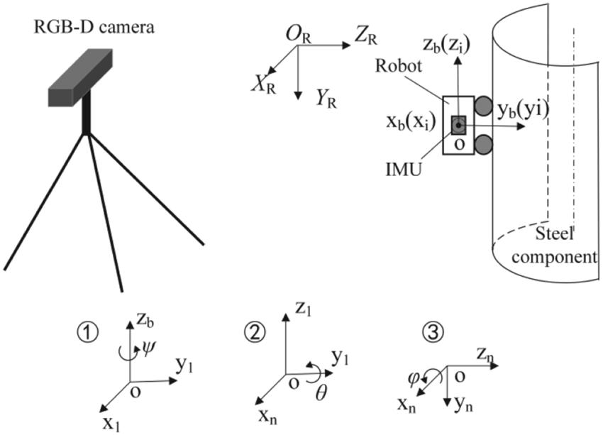
Figure 1 shows the hardware diagram of the RGBD-IMU-AL system. The IMU coordinate system is ox iy iz i, and the robot body coordinate system is ox by bz b. The camera coordinate system is O RX RY RZ R. The navigation coordinate system is O Rx ny nz n. The axis y n parallels to the axis Y R and the axis z n points north. The Euler angles (roll angle ϕ, pitch angle θ and heading angle ψ) are used to describe the rotation matrix ${}_b^n{\boldsymbol C}$ . (ϕ, θ, ψ) is defined as follows: The first rotation is about the axis z b by an angle ψ, leading to the ox 1y 1z b coordinate system; the second rotation is about the axis y 1 by an angle θ, leading to the ox ny 1z 1 coordinate system; the third rotation is about the axis x n by an angle ϕ, leading to the ox ny nz n coordinate system. Then, the origin of the ox ny nz n coordinate system is moved from o to O R. The rotation matrix ${}_b^n{\boldsymbol C}$
 corresponding to the order of the defined Euler angles is expressed as follows:

where the subscript s represents the sine function, and c represents the cosine function.
Hardware diagram of RGBD-IMU-AL system

3. RGBD-IMU-AL method
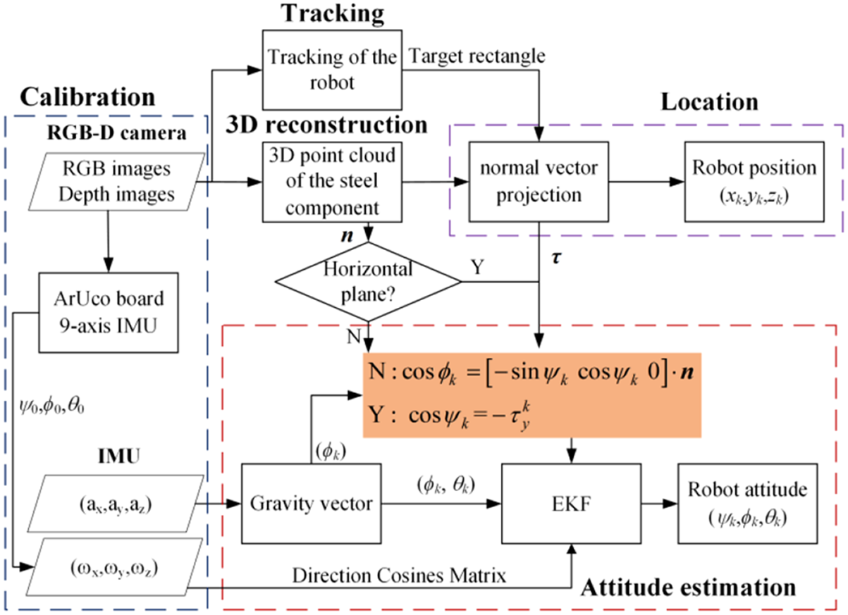
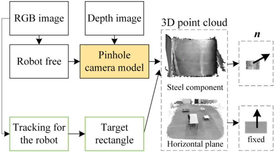
Figure 2 illustrates the main framework of the proposed approach. The RGBD-IMU-AL method includes five modules. The calibration process of the sensors is described in Section 3.1. The tracking module (Section 3.2) and 3D reconstruction module (Section 3.3) are used to process the information from the RGB-D camera, which is the preparation step of location process. The location module based on the normal vector projection (Section 3.4) is the most important part of the proposed method. The attitude estimation module is implemented by an EKF (Section 3.5).
Framework of RGBD-IMU-AL method

3.1 Calibration of the RGB-D camera and IMU
Before the experiment, the gyroscope and accelerometer in the IMU are calibrated using the IMU Toolkit (Valenti et al., Reference Valenti, Dryanovski and Xiao2015), and the RGB-D camera is calibrated using the checkerboard method (Wiedemeyer, Reference Wiedemeyer2015). The transformation matrix of the camera coordinate system with respect to the navigation coordinate system is ${\boldsymbol C}({{\psi_0},{\phi_0},{\theta_0}} )$ , where ${\psi _0}$
 is the initial heading angle, ${\phi _0}$
 is the initial roll angle and ${\theta _0}$
 is the initial pitch angle.
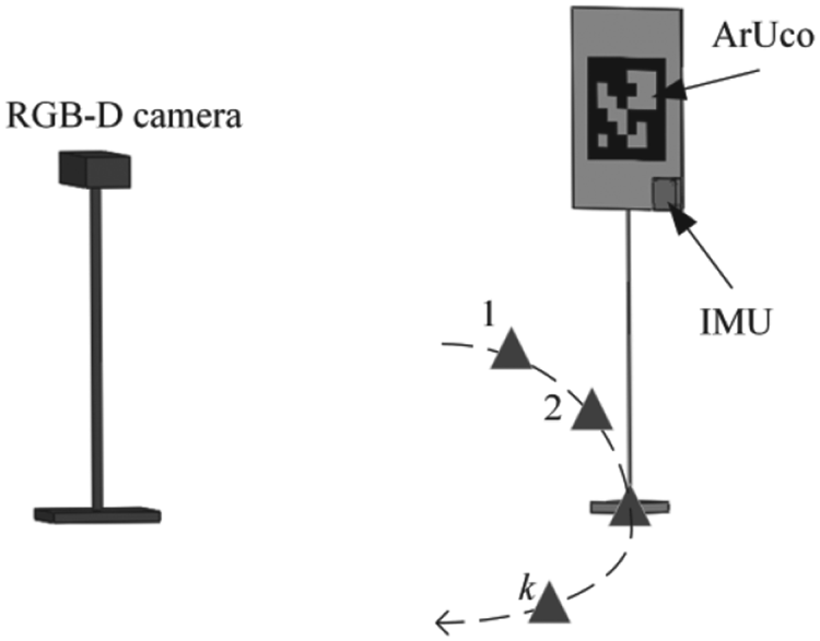
The IMU containing a three-axis magnetometer is mounted on the ArUco plane as shown in Figure 3. The ArUco is shifted from Position 1 to Position k(k ≥ 3), and the magnetic field intensity $({m_x^k,m_y^k,m_z^k} )$ and acceleration $({a_x^k,a_y^k,a_z^k} )$
 are recorded from the IMU. ${\theta _k}$
 and ${\phi _k}$
 can be calculated using Equation (2).

$({M_x^k,M_y^k,M_z^k} )$ is the magnetic field intensity in the navigation coordinate system. The heading angle ${\psi _k}$
 of the ArUco is calculated using Equations (3)–(6):


The rotation matrix ${\boldsymbol C}_k^A$ of the ArUco relative to the camera coordinate system is determined through the ArUco detection library in OpenCV (Romero-Ramirez et al., Reference Romero-Ramirez, Muñoz-Salinas and Medina-Carnicer2018). ${\psi _0}$
 ,${\phi _0}$
 and ${\theta _0}$
 are calculated as follows:

Calibration of the initial attitude angle

3.2 Tracking of the wall climbing robot
Only the area occupied by the wall-climbing robot in the field of the RGB-D camera is changed during the localisation, which is the region of interest (ROI). To speed up the proposed algorithm, a target-tracking algorithm based on a combination of deep learning and KCF (Henriques et al., Reference Henriques, Caseiro, Martins and Batista2014) is used to obtain the ROI and preliminary position of the robot.
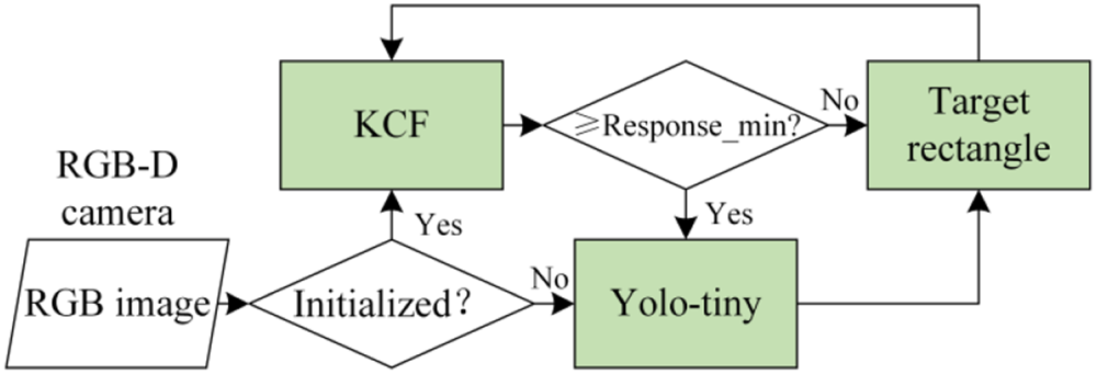
Figure 4 shows the tracking of the wall-climbing robot . Firstly, Yolo-Tiny (Redmon and Farhadi, Reference Redmon and Farhadi2018) is used to find the initial location of target rectangle. Then, taking the initial location and the current frame as the input, KCF is adopted for real-time tracking in the next frame. The Yolo-Tiny is used to relocate the target rectangle when the response value is less than the threshold.
Tracking module

3.3 3D reconstruction of steel components
During the movement of the wall-climbing robot, there is no change in the pixels of the large component in the images acquired by the RGB-D camera. The 3D reconstruction of the steel component is conducted to obtain the 3D point cloud, which is used in the subsequent localisation to obtain the normal vector of the robot chassis, as shown in Figure 5.
3D reconstruction module

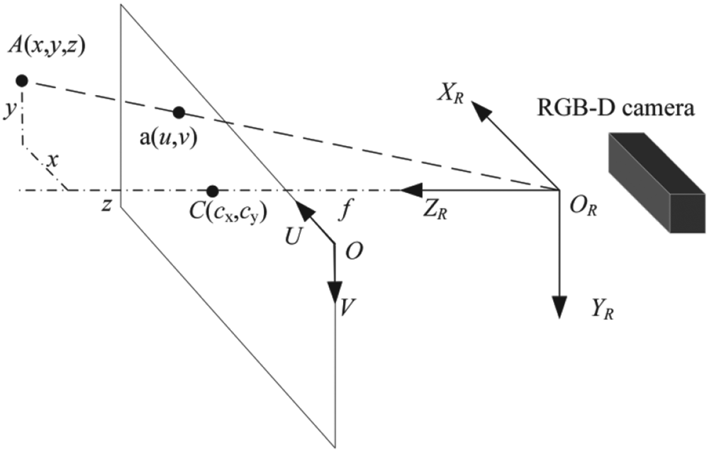
Figure 6 shows a schematic of the pinhole camera model, which describes the mathematical relationship between a point in 3D space and its projection onto the image plane. The pixel coordinate system UOV is defined with the U and V axes parallel to the X R and Y R axes, respectively. The centre point C (c x, c y) in the camera coordinate system is (0, 0, f), and f is the focal length. A point A(x, y, z) in space is projected to point a(u, v) on the image plane, and the 3D coordinates of A in the camera coordinate system are obtained as follows:

where s is the distance scale of the RGB-D camera, and d is the distance from the point to the camera plane. The parameters ${c_x}$ , ${c_y}$
 , ${f_x}$
 and ${f_y}$
 are obtained by calibration.
The pinhole camera model

3.4 Location based on normal vector projection
Since the range of the target rectangle (obtained in Section 3.2) exceeds the size of the robot itself, only a rough estimate of the position can be obtained after tracking the robot. To solve this problem, a location method based on normal vector projection is proposed.
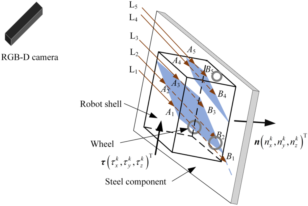
As shown in Figure 7, in the field of view of the RGB-D camera, the points B 1-B 5 on the large component move along the optical path L1–L5 to points A 1–A 5 on the robot shell, respectively, due to the occlusion of the wall-climbing robot. The lengths of the lines L1 and L2 on the top of the robot are reduced by | A 1B 1| and | A 2B 2|, respectively, in the direction of the light path, while the lengths of the lines L3-L5 on the side of the robot are reduced by | A 3B 3|, | A 4B 4|, and | A 5B 5|, respectively.
Length changes in the depth direction caused by the robot

Let point a(u, v) in the pixel coordinate system correspond to point $A({x,y,z} )$ on the robot. When there is no occlusion caused by the robot, the point a corresponds to point $B({x^{\prime},y^{\prime},z^{\prime}} )$
 on the surface of the large component, and the inclined line ${\boldsymbol AB}$
 is expressed as follows:

where $\varDelta d({u,v} )$ is the depth change caused by robot occlusion at the pixel a(u, v).
However, the length of ${\boldsymbol AB}$ is related to (u, v) and cannot be directly used to distinguish between the point clouds on top of and around the robot shell, according to Equation (9).
Let ${\boldsymbol n}({n_x^k,n_y^k,n_z^k} )$ be the normal vector of the robot chassis, which is collinear with the normal vector (as shown in Figure 5) in the contact area. The inclined line ${\boldsymbol AB}$
 is projected along the vector ${\boldsymbol n}$
 to obtain h(j) in Equation (10). The height of the robot is H. The value of h(j) corresponding to the top of the robot is approximately equal to H, while the side is less than H:

In the 3D point set $\{{{k_j}|{h(j )= H} } \}$ of the robot top, the midpoint $P({{p_x},{p_y},{p_z}} )$
 is selected as the position of the robot.

3.5 Attitude estimation based on EKF
After the wall-climbing robot reaches the destination, it also needs to adjust the posture of the mechanical arm according to its own attitude in several industrial tasks such as welding, cleaning and detection. Due to the interference of strong magnetic field, a magnetometer cannot be used to correct the heading angle of the wall-climbing robot. Here, an attitude-estimation method based on EKF is proposed to reduce the error accumulation of the heading angle.
The wall-climbing robot moves at a low speed on the surface of large components with an acceleration close to zero. The three-axis output $({a_x^k,a_y^k,a_z^k} )$ of the accelerometer in IMU is approximately equal to the three components of the gravity vector in the body coordinate system. The pitch angle ${\theta _k}$
 and roll angle ${\phi _k}$
 can be calculated using Equation (2).
In the EKF, the state ${{\boldsymbol x}_k}$ consists of the cosine and the sine of the heading angle:

where ${{\boldsymbol x}_k}$ can be obtained by multiplying the first two elements of the first column of ${}_b^n{{\boldsymbol C}_k}$
 by the factor ${({\cos {\theta_k}} )^{\textrm{ - }1}}$
 . ${}_b^n{{\boldsymbol C}_k}$
 is updated using Equations (13)–(15).


where $\omega _x^k$ , $\omega _y^k$
 and $\omega _z^k$
 are the angular velocities of IMU at time k. $b_x^k$
 , $b_y^k$
 and $b_z^k$
 are the angular velocity drifts of the IMU at time k.
With the pitch angle ${\theta _k}$ at time k obtained by Equation (2), the state transition function of the EKF is shown in Equation (16).


where ts is the sampling time of IMU, and ${\boldsymbol W}_\psi ^k$ is the zero mean white Gaussian noise.
The normal vector ${\boldsymbol n}({n_x^k,n_y^k,n_z^k} )$ of the robot chassis is calculated through the 3D point cloud of large components obtained in Section 3.3. The vector ${\left( {\begin{array}{*{20}{c}} 0& 1& 0 \end{array}} \right)^\textrm{T}}$
 is determined by converting ${\boldsymbol n}({n_x^k,n_y^k,n_z^k} )$
 from the navigation coordinate system to the robot body coordinate system,

Solving the simultaneous Equations (1) and (19) and eliminating θk, we get

According to the above relationship between ${\boldsymbol n}({n_x^k,n_y^k,n_z^k} )$ and the heading angle, the measurement function of the EKF is divided into two cases.
(i) $n_y^k \ne 0$
 or $n_x^k \ne 0$:
(21)\begin{align} {}^1{{\boldsymbol z}_k} & =\cos {\phi _k}\nonumber\\ {}^1{{\boldsymbol z}_{k\textrm{|}k - 1}} & = {H_1}{x_{k|k - 1}} + {}^1{v_k}\nonumber\\ {H_1} & = \left({\begin{array}{@{}cc@{}} {n_y^k}& { - n_x^k}\end{array}}\right) \end{align}


where ${}^1{v_k}$ is the measurement noise.
The state noise autocorrelation matrix ${{\boldsymbol Q}_k}$ and covariance matrix ${}^1{{\boldsymbol R}_k}$
 are expressed as


where $\sigma _{\psi 1}^2$ and $\sigma _{\psi 2}^2$
 are the estimated variances of $\cos {\psi _k}$
 and $\sin {\psi _k}$
 , respectively. $\sigma _\phi ^2$
 is the measurement noise variance of $\cos {\phi _k}$
 .
${\boldsymbol d}$ is the normalised factor of the state ${{\boldsymbol x}_k}$
 , which is defined as

The update steps of the EKF are:


(ii) $n_y^k = 0$
and $n_x^k = 0$. That is, the wall-climbing robot moves in the horizontal plane. Under magnetic interference conditions, the principal components analysis (PCA) method (Tharwat, Reference Tharwat2016) is adopted to calculate the first principal component ${\boldsymbol \tau }({\tau_x^k,\tau_y^k,\tau_z^k} )$ of the 3D point set $\{{{k_j}|{h(j )= H} } \}$ of the robot top, which is the orientation of the wall-climbing robot, as shown in Figure 7.


The vector ${\boldsymbol \tau }({\tau_x^k,\tau_y^k,\tau_z^k} )$ is parallel to the z b axis of the robot body coordinate system ox by bz b. The vector ${\left( {\begin{array}{*{20}{c}} 0& 0& 1 \end{array}} \right)^\textrm{T}}$
 is determined by converting ${\boldsymbol \tau }({\tau_x^k,\tau_y^k,\tau_z^k} )$
 from the navigation coordinate system to the robot body coordinate system.
Replacing ${\left( {\begin{array}{*{20}{c}} 0& 1& 0 \end{array}} \right)^\textrm{T}}$ and ${\boldsymbol n}({n_x^k,n_y^k,n_z^k} )$
 in Equation (19) with ${\left( {\begin{array}{*{20}{c}} 0& 0& 1 \end{array}} \right)^\textrm{T}}$
 and ${\boldsymbol \tau }({\tau_x^k,\tau_y^k,\tau_z^k} )$
 , we get

According to Equation (26), the measurement function of the EKF is expressed as

where ${}^2{v_k}$ is the measurement noise.
The covariance matrix ${}^2{{\boldsymbol R}_k}$ is shown in Equation (28).

where $\sigma _{\tau y}^2$ and $\sigma _{\tau x}^2$
 are the estimated variances of $\tau _y^k$
 and $\tau _x^k$
 , respectively.
The EKF update steps in (ii) are the same as that in (i), and ${}^1{z_k}$ ,${}^1{z_{k|k - 1}}$
 ,${H_1}$
 ,${}^1{{\boldsymbol R}_k}$
 and ${}^1{v_k}$
 are replaced by ${}^2{z_k}$
 ,${}^2{z_{k|k - 1}}$
 ,${H_2}$
 ,${}^2{{\boldsymbol R}_k}$
 and ${}^2{v_k}$
 in Equation (25).
4. Experimental results and discussion
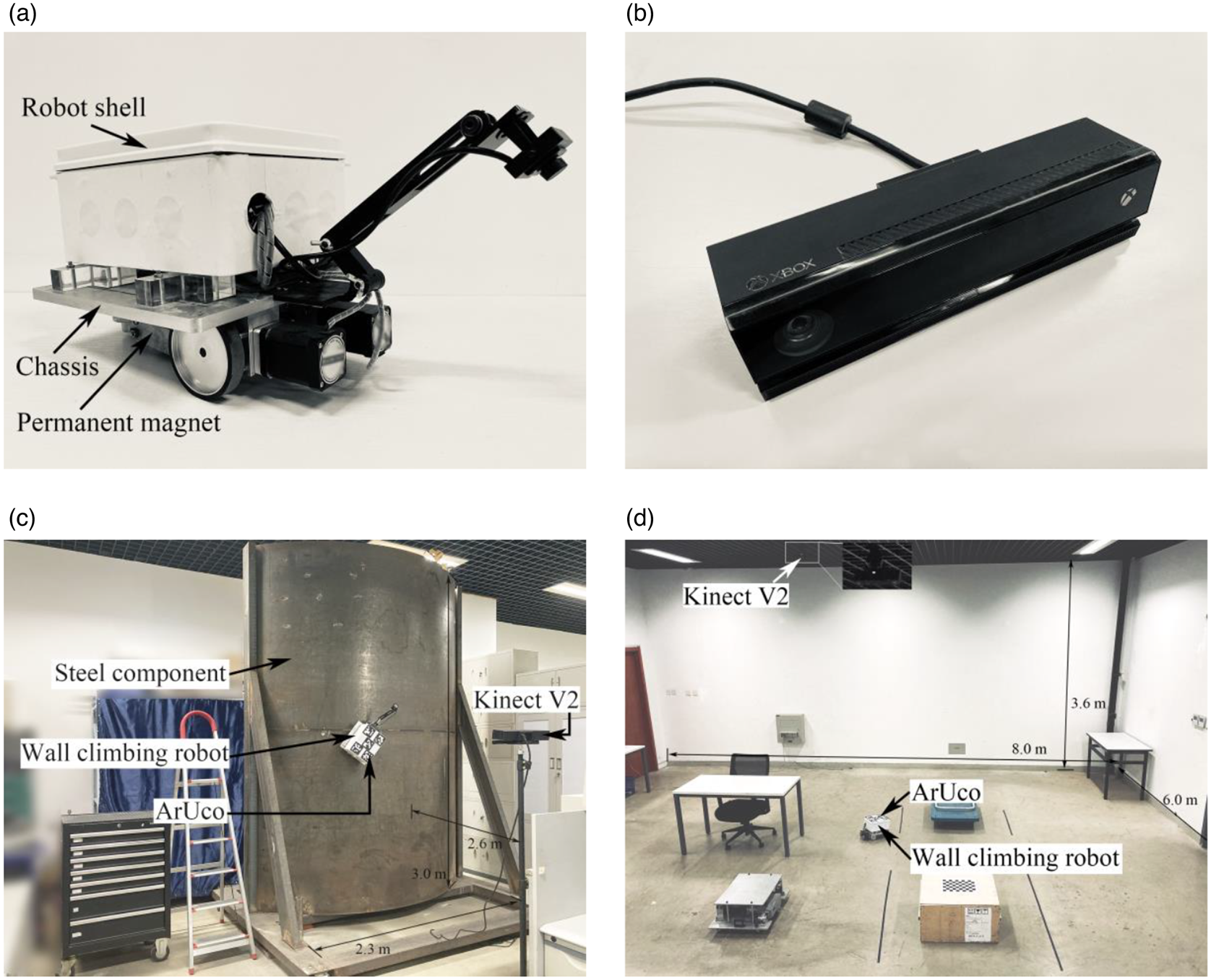
A wheeled wall-climbing robot (0⋅25 m × 0⋅19 m × 0⋅20 m, in Figure 8a) equipped with an ADIS16490 IMU was used to conduct experiments on a large cylindrical steel component (2⋅3 m × 3⋅0 m, in Figure 8c) and in a room (8⋅0 m × 6⋅0 × 3⋅6 m, in Figure 8d). The colour images (1,920 × 1,080) and depth images (512 × 424) were collected by a fixed Microsoft Kinect V2 camera (in Figure 8b). The image acquisition frequency was 10 Hz. The sampling frequency of IMU was 100 Hz. The parameters of the IMU are as follows: (1) For the internal triaxial gyroscope, the run bias stability is 1⋅8°/h, and the angular random walk is 0⋅09$^ \circ{/}\sqrt{ \textrm{h}}$ . The output noise is 0⋅05°/s rms. (2) For the internal triaxial accelerometer, the run bias stability is 3⋅6 $\mathrm{\mu g}$
 , and the output noise is 0⋅5 mg rms. The method was implemented in Ubuntu 18⋅04 LTS, on a laptop (CPU: Intel i7-11800 H, graphics card: RTX 3060, 16 GB RAM).
Test equipment and real environment used for testing: (a) the wall-climbing robot equipped with an ADIS16490 IMU; (b) Microsoft Kinect V2 camera; (c) a large cylindrical steel component and the experimental system for RGBD-IMU-AL; (d) a room with a horizontal plane for extended application of the RGBD-IMU-AL method

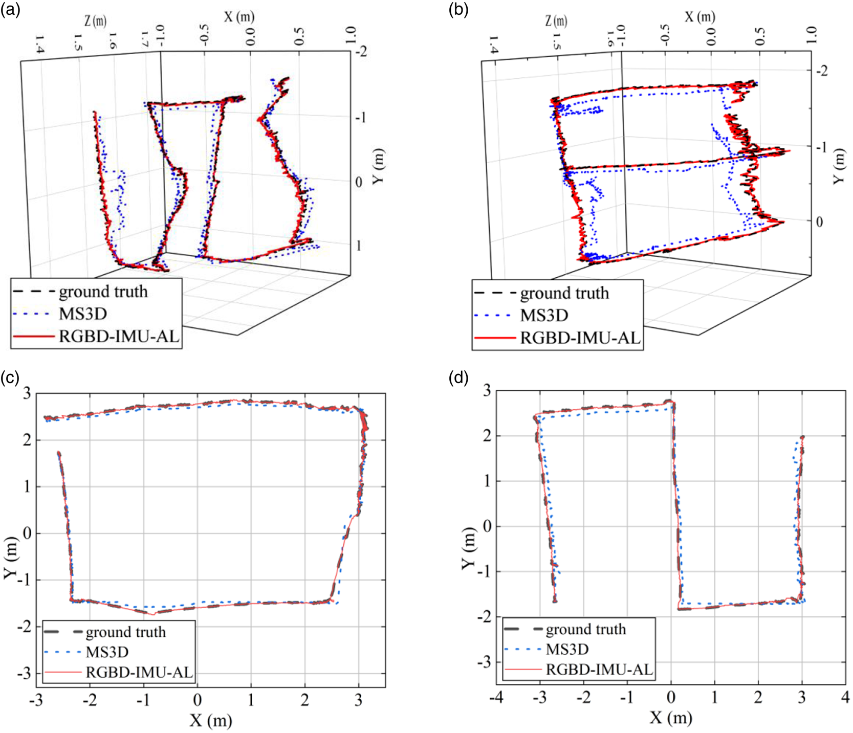
To verify the effectiveness of the proposed RGBD-IMU-AL method, the wall-climbing robot was allowed to move along different paths on the large steel component and in the room. Figure 9 shows the trajectories (Path 1~Path 4) . Each experiment was repeated 50 times. Under sufficient light conditions, the ArUco marker detection method was adopted to calculate the true position and attitude of the wall-climbing robot. The calibration and 3D reconstruction modules ran only once at the beginning. The total running time for processing each frame did not exceed 0⋅096 s, and the proposed algorithm achieved real-time localisation.
Trajectories in real environments. Comparison between the absolute trajectories of the proposed and MS3D methods in different paths: (a) Path 1 on a large cylindrical steel component; (b) Path 2 on a large cylindrical steel component; (c) Path 3 in a room; (d) Path 4 in a room

4.1 Evaluation of the normal vector estimation ability
As an important intermediate variable of the RGBD-IMU-AL method, the normal vector of the robot chassis directly affects the accuracy of the autonomous localisation. The normal vector error ${e_n}$ is defined in Equation (29), where ${{\boldsymbol n}_g}$
 is the real normal vector, obtained by the ArUco marker detection method:

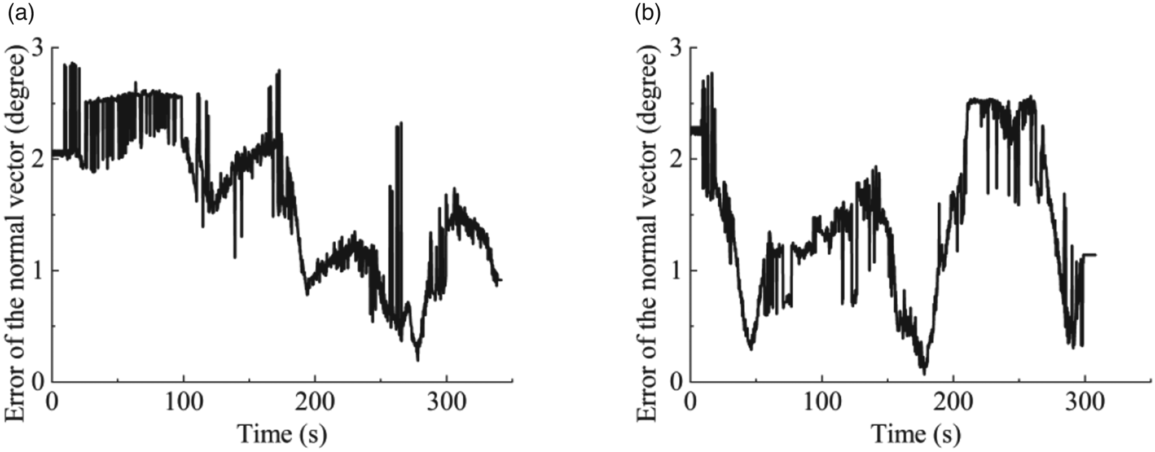
When the wall-climbing robot moves in a room with a horizontal plane, its chassis normal vector is fixed and equal to the normal vector of that plane. Therefore, the focus is on evaluating the normal vector of the robot chassis when the robot moves on the steel component (Figure 8b). As shown in Figure 10, the normal vector error does not exceed 3° in the proposed method. According to Section 3.4, the normal vector error determines the accuracy of positioning. According to Equation (20) in Section 3.5, the heading angle is estimated using the normal vector as an observation vector. Reducing the estimation error of normal vector is a focus of our future work.
Errors of the robot chassis normal vector in different paths: (a) Path 1; (b) Path 2

4.2 Evaluation of the position estimation ability
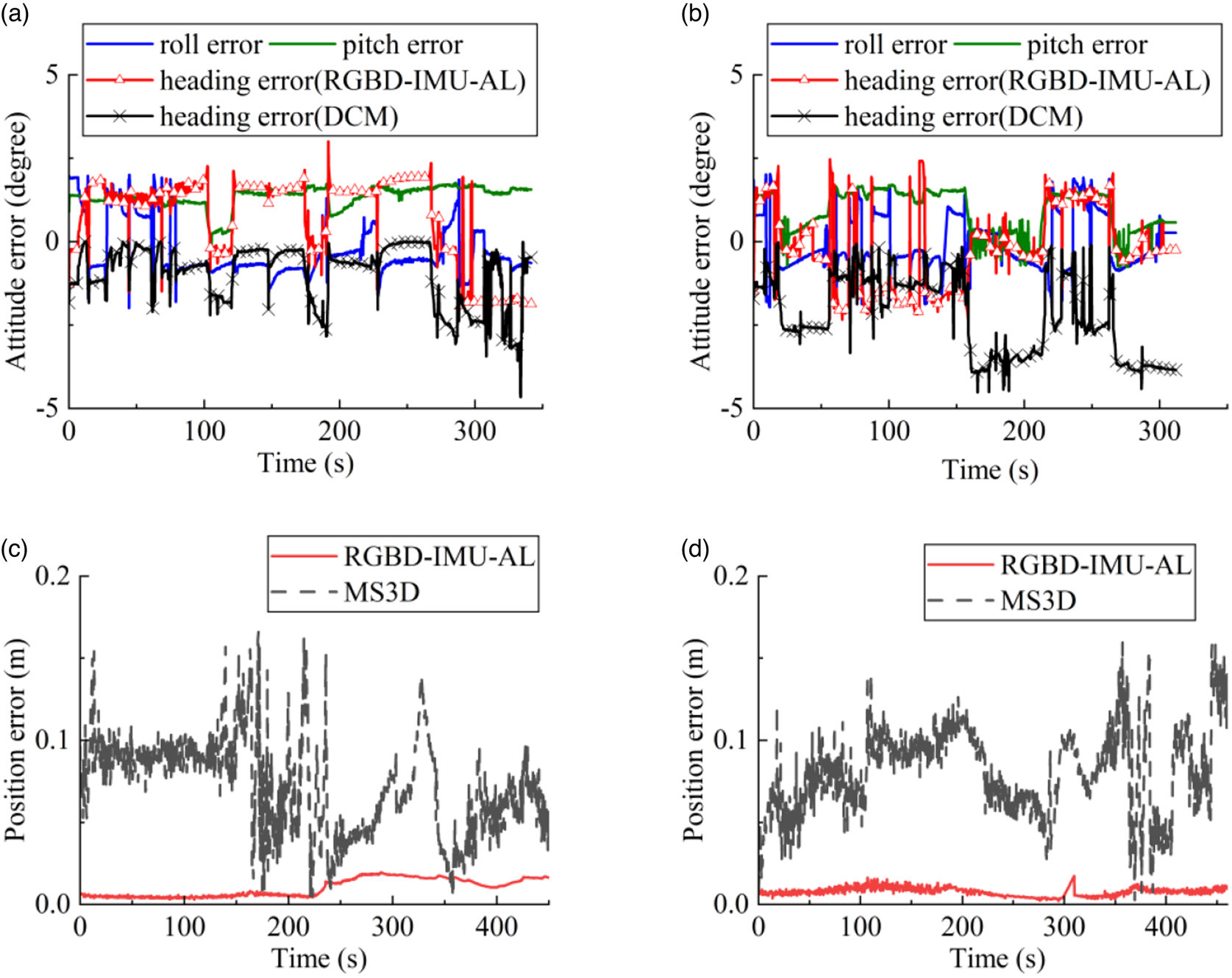
The MS3D method has higher positioning accuracy than other fixed-vision methods, so its performance is compared with that of the RGBD-IMU-AL method. The absolute trajectory error (ATE) ${e_p}$ is defined in Equation (30), where $({{p_x},{p_y},{p_z}} )$
 is obtained in Equation (11) and $({{p_{gx}},{p_{gy}},{p_{gz}}} )$
 is the real position of the robot:

The absolute trajectories of the wall-climbing robot are illustrated in Figure 9. It is clear that the trajectories obtained by the RGBD-IMU-AL method are consistent with the ground truth.
The maximum ATE values for RGBD-IMU-AL and MS3D method are 0⋅02 m and 0⋅17 m, respectively. It can be seen from the peaks in Figure 11 that the RGBD-IMU-AL method has a much smaller deviation from the real value. When the robot moves on the cylindrical steel component, the mean absolute error of the proposed method and MS3D method are 0⋅01 m and 0.075 m, respectively. When the robot moves in the room, the mean absolute error of the proposed method and MS3D method are 0⋅013 m and 0⋅075 m, respectively.
Comparison between absolute errors of the proposed and MS3D methods in different paths: (a) Path 1; (b) Path 2; (c) Path 3; (d) Path 4

The experiments results prove that the RGBD-IMU-AL method can effectively locate the wall-climbing robot, meeting the positioning requirements of industrial tasks and path planning.
4.3 Evaluation of the attitude estimation ability
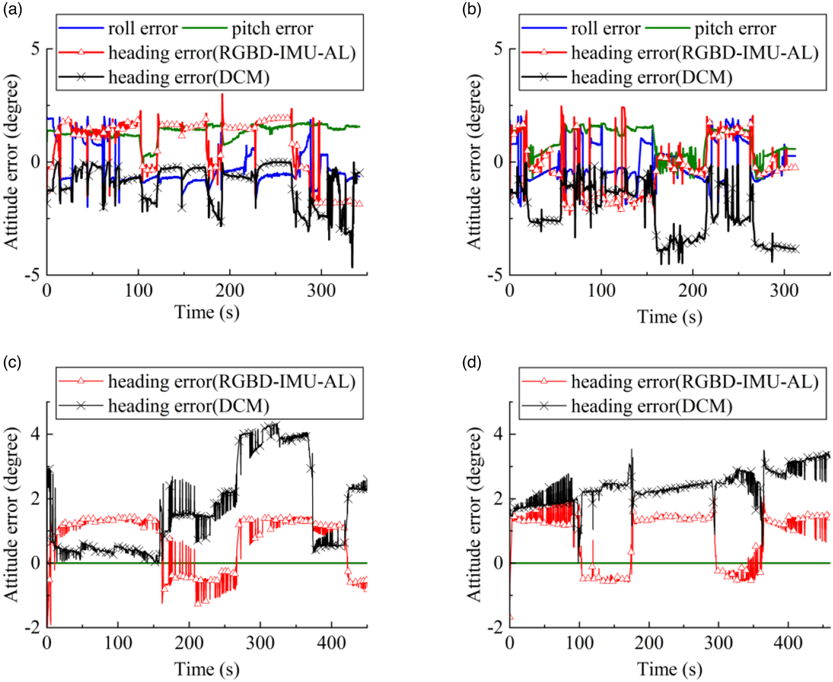
The existing fixed-vision methods are not suitable for the attitude estimation of low-texture wall-climbing robots (Figure 8a) in terms of real-time performance and accuracy. Therefore, we use the IMU-based DCM method (Wang and Rajamani, Reference Wang and Rajamani2018) to compare with the RGBD-IMU-AL method under magnetic interference conditions. Since the cited two methods estimate the roll angle and pitch angle through the direction of gravity, as shown in Equation (2), we focus on the performance of heading-angle estimation.
Figure 12 illustrates the attitude errors represented by Euler angles. When the robot moves on the cylindrical steel component, the maximum pitch angle error is 2⋅1°, and the maximum roll angle error is 2⋅4°, as shown in Figures 12a and 12b. When the robot moves in the room, the horizontal ground drives the pitch angle (θ = 0°) and the roll angle (ϕ = −90°) to be fixed, according to the definition of the navigation coordinate system in Figure 1.
Attitude error of the proposed method in different paths. The roll angle error and the pitch angle error are zero in Path 3 and Path 4: (a) Path 1; (b) Path 2; (c) Path 3; (d) Path 4

It is evident that the maximum heading angle error using the DCM method is 4⋅7°, which accumulates over time, while it remains within 3⋅1° using the RGBD-IMU-AL method. The heading-angle error caused by Equation (16) can be reduced by the EKF observation in Equation (21) or Equation (27), which is related to the normal vector of the robot chassis. When the robot moves on the cylindrical steel component, the mean heading error of the proposed method and MS3D method are 0⋅19° and 2⋅25°, respectively. When the robot moves in the room, the mean heading error of the proposed method and MS3D method are 0⋅73° and 2⋅17°, respectively. Therefore, the RGBD-IMU-AL method provides a novel solution for the estimation of heading angle under magnetic interference conditions.
5. Conclusion
In this study, we presented the RGBD-IMU-AL method based on the fusion of a fixed RGB-D camera and a robot-mounted IMU. This method is extremely effective for robot localisation under the condition of GPS failure and magnetic interference. An algorithm based on the combination of learning-based Yolo-Tiny and KCF was used to improve the stability and speed of motion tracking. Furthermore, we proposed a normal vector projection algorithm to locate the robot based on the morphological features. To avoid the accumulation of heading-angle errors over time under magnetic interference, the quantitative relationship between the normal vector of the robot chassis and the heading angle was examined, and an EKF was designed to estimate the attitude accordingly. The experimental results proved that the RGBD-IMU-AL method performs better than the MS3D method in terms of the positioning error. When a magnetometer is not available, compared with the DCM method, the proposed method can effectively maintain the heading angle error at a consistently low level. This method exhibits immense application potential in various wall-climbing robots for fully automated operations, such as cleaning, flaw detection and welding. With the widespread application of unmanned aerial vehicles (UAVs) and unmanned vehicles, the proposed method is also applicable to the path planning and efficient obstacle avoidance of vehicles outside the highway by the UAVs. In addition, it is helpful for the localisation and scheduling of unmanned vehicles in the field of view of the surveillance cameras.
In future work, we hope to develop multi-camera fusion methods to expand the camera's field of view for wall-climbing robots working in larger regions. In addition, we will consider adding encoders to the wheel shafts and combining a vehicle odometry (Rijalusalam and Iswanto, Reference Rijalusalam and Iswanto2021) to improve the robustness of the proposed method in cases of local occlusion.
Acknowledgements
The work is supported by the National Natural Science Foundation of China (E51475259). The authors would like to thank the reviewers for their constructive comments.
Competing interests
The authors declare none.