Introduction
Particle-reinforced metal matrix composites (PRMMCs) exhibit superior properties compared to traditional materials, including high specific strength, high specific stiffness, and excellent wear resistance. As a result, these materials are widely used as raw materials for industrial products or equipment parts for machinery and automobiles [Reference Ghosh and Saha1, Reference Losch, Schuff, Balle, Beck and Redenbach2, Reference Afkham, Khosroshahi, Rahimpour, Aavani, Brabazon and Mousavian3, Reference He, Ertuğrul, Ciftci, Uhlenwinkel, Nielsch and Scudino4, Reference Liu, Ding, Yu and Yang5]. Increasing attention is being paid to cast tungsten carbide particle/steel matrix surface composites because of the high melting point and high hardness of cast tungsten carbide particles, particularly the good wettability attained with a ferroalloy melt, and the easy and low-cost preparation of these composites.
Cast tungsten carbide particle/steel matrix surface composites are usually used under conditions of variable temperatures and alternating cyclic stress loads, such as in hot forging and hot rolling [Reference Lou, Hellman, Luhulima, Liimatainen and Lindroos6]. Under these thermal shock wear conditions, thermal fatigue cannot be ignored, as it may result in malignant failure of the material. A number of studies have been conducted on SiC-PRMMCs. For instance, Wei [Reference Wei, Zhenhua, Ding, Cang and Canrang7], Wu [Reference Wu and Han8], and Pan [Reference Pan, Han, Yang, Li, Wang, Li and Li9] et al. studied the thermal fatigue behavior of SiC particle-reinforced Al matrix composites and found that the thermal fatigue crack initiated from the notch tip of the composites. A review article on the cracking evolution behavior of lightweight materials by Luo et al. [Reference Luo, Wu, Hu and Fu10] noted that fatigue cracking usually initiated from either the SiC particle or voids in the matrix. Wang et al. [Reference Wang, Li and Tao11] investigated the thermal fatigue behavior of tungsten carbide particle-reinforced Fe matrix composites produced through laser melting deposition and found that cracks were prone to form in larger particles. However, for the cast tungsten carbide particle/steel matrix surface composites fabricated via vacuum evaporative pattern casting (V-EPC) in this study, this may not be the case. Owing to differences in thermophysical properties between the components, such as the thermal expansion coefficient and thermal conductivity, thermal stress is easily generated and accumulated at the interface reaction zone (IRZ) between the matrix and the reinforcing particles [Reference Pan, Han, Yang, Li, Wang, Li and Li9]. This leads to preferential initiation of thermal fatigue cracks at the IRZ, which is one of the main causes of PRMMC failure [Reference Lu, Lai and Ng12]. As a result of the IRZ between the particles and the matrix [Reference You, Song, Ren, Ma, Huang and Zhang13] and the transition layer (TL) between the composite and the substrate, micro-cracks were preferentially initiated at the IRZ and then connected to form macro-cracks along the TL, resulting in crack initiation and propagation behaviors that are more complicated than those of other PRMMCs [Reference Shorowordi, Laoui, Haseeb, Celis and Froyen14, Reference Inem15, Reference Zhou, Jiang and Sui16, Reference Chen, Tao, Liu, Bao, Li, Li and Yi17]. Thus, obtaining a better understanding of the interfacial thermal fatigue behavior of cast tungsten carbide particle/steel matrix surface composites is necessary.
To date, many studies have been conducted on the thermal fatigue behavior of PRMMCs [Reference Chawla and Ganesh18, Reference Pippan, Flechsig and Riemelmoser19]. Li [Reference Li, Jiang, Zhou, Gao, Shan and Tan20] et al. studied the thermal fatigue mechanism of tungsten carbide particle-reinforced steel matrix composites, and revealed that thermal stress caused the thermal fatigue failure of tungsten carbide particles. Zhou [Reference Zhou, Zeng, Hu and Huang21] et al. investigated the crack behavior of Ni-based tungsten carbide composites coated by laser cladding and found that cracks were initiated at the interface between the composite coating and the substrate. Zhou [Reference Zhou, Long and Liu22] et al. studied SiC PRMMCs by a laser beam and concluded that crack propagation was related to the fracture of the SiC particles.
However, most studies on cast tungsten carbide particle/steel matrix surface composites have focused on their wear performance [Reference You, Song, Ren, Ma, Huang and Zhang13, Reference Montgomery23, Reference Zhong, Xu, Yu, Liu, Ye and Yan24], and little is known about their interfacial thermal fatigue behavior. The crack initiation and propagation behaviors at the IRZ of cast tungsten carbide particle/steel matrix surface composites are complex and still not well understood. Therefore, this study aimed to investigate the interfacial thermal fatigue behavior of cast tungsten carbide particle/steel matrix surface composites through thermal shock experiments. The magnitude and state of internal stress at different locations were explored, and the crack initiation and propagation were analyzed to establish the surface composite interface mechanism of the thermal fatigue behavior more clearly.
Results and discussion
IRZ and TL of surface composites
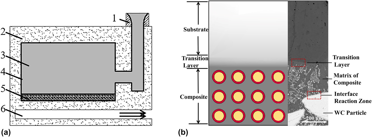
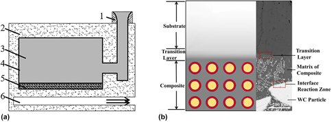
Figure 1 shows a schematic of the composite preparation. In the third step of the surface composite preparation, two types of interfaces are formed. As shown in Fig. 1(b), as the molten metal infiltrated the preform layer, the cast tungsten carbide particles were surrounded by the ferroalloy matrix, and an interface reaction between the particles and the matrix occurred, forming the IRZ. As a result, the composite composed of tungsten carbide particles and an infiltrated ferroalloy matrix was formed. When the expandable polystyrene (EPS) pattern was filled with the ferroalloy substrate, the tungsten carbide particles near the substrate mostly melted owing to the high temperature of the molten metal. As a result, W and C diffused toward the substrate, and because of the interdiffusion effect, Cr and Fe spread into the matrix, forming a TL. Meanwhile, some carbides were produced at the TL, achieving a good metallurgical bond between the composite and the substrate.
Schematic of the composite preparation: (a) V-EPC infiltration principle: (1) sprue, (2) quartz sand, (3) EPS, (4) coating, (5) preform, (6) vacuum sucker; (b) the cast tungsten carbide particle/steel matrix surface composite.

Fatigue cracks at the IRZ and TL
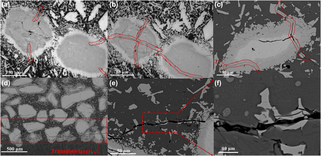
Figure 2 shows the fatigue crack morphology in the surface composites. It can be seen that the micro-cracks were initiated from the IRZ in the direction perpendicular to the interface, then propagated rapidly into the center of the particle after only two cycles, and finally passed all the way through the particle, as shown in Figs. 2(a) and 2(b). This behavior indicates that the IRZ effectively transmitted stress from the matrix to the reinforced particles. These observations are consistent with the results reported by Wang [Reference Wang, Li and Tao11], Zhou [Reference Zhou, Zeng, Hu and Huang21], and Ignat [Reference Ignat, Sallamand, Nichici, Vannes, Grevey and Cicalã25] for laser cladding. With an increasing number of thermal shock cycles, the micro-cracks began to propagate to the carbides in the matrix, and the cracks widened, as shown in Fig. 2(c). Compared with other areas of the composite, as shown in Fig. 2(d), more cracks were observed at the TL, and the cracks were much wider after the same number of cycles. This indicates that the thermal stress was greater at this location, and the micro-cracks continued to grow until finally connecting to form macro-cracks near the TL. As shown in Figs. 2(e) and 2(f), the crack propagation exhibited the same trend at the IRZ, where they continued to propagate and finally became connected.
Thermal fatigue crack morphology in the surface composites: cracks in the tungsten carbide particle of the composite after (a) one cycle, (b) two cycles, and (c) 15 cycles; (d) cracks at the TL after 15 cycles; (e) cracks in the matrix after 30 cycles; (f) enlargement of the red box area outlined in (e).

Fatigue crack behavior mechanism
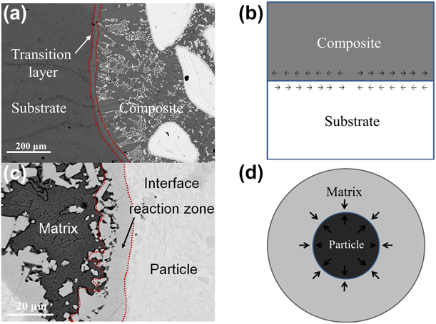
Thermal fatigue behavior is affected by many factors, of which thermal stress is one of the main contributors. Figure 3 shows the interfacial stress at the IRZ and TL of the surface composites. It has been established that some carbides were produced at the TL, as described in the section “IRZ and TL of surface composites,” and there were significant differences in the coefficient of thermal expansion (CTE) between the different components. During the thermal cycles, interaction forces will occur between the composite and the substrate due to volume shrinkage or expansion, as shown in Figs. 3(a) and 3(b). Thus, thermal stress appeared, resulting in the initiation of cracks at the TL. There was also a CTE mismatch between the cast tungsten carbide particle and the matrix, and thus, the same interaction would be produced between the particle and the matrix, as shown in Fig. 3(d). Because an interface reaction occurred between the particle and the matrix, and more carbides were produced at the IRZ, the thermal stress was more prone to be generated and concentrate at the IRZ, leading to a strong tendency for cracks to initiate there. This is consistent with the preferential initiation of micro-cracks at the IRZ observed in Fig. 2(a).
Interface structure and interface stress of surface composites: (a) TL, (b) schematic of stress at the TL, (c) IRZ, (d) schematic of stress at the IRZ.

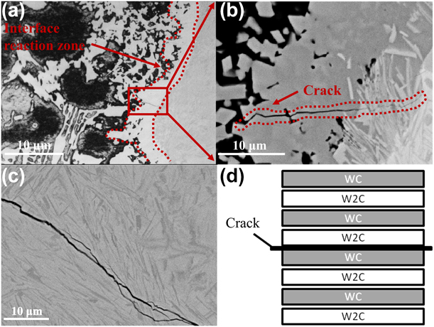
Figure 4 shows the initiation and propagation of thermal cracks in the composite. Because the cast tungsten carbide particles are composed of WC and W2C, stress concentration also occurred at the interface between the WC and W2C, which increased the probability of cracks propagating toward the particles after initially appearing in the IRZ, as shown in Figs. 2(b) and 4(b). Moreover, it can be seen in Fig. 4(c) that the cracks in the particles clearly propagated along the interface between WC and W2C. This phenomenon is consistent with the results reported by Liu [Reference Liu, Chen, Li and Li26], who found the interface of WC and W2C was the weakest location in the particle/matrix reaction zone, and cracking occurred along the interface between WC and W2C. The crack will not propagate into the matrix until it has passed through the entire particle, resulting in fracture of the cast tungsten carbide particle, as shown in Fig. 2(f).
Micro-topography of fatigue cracks: (a) cracks at the IRZ, (b) enlargement of the red box area outlined in (a), (c) cracks in a tungsten carbide particle, (d) schematic of the crack position.

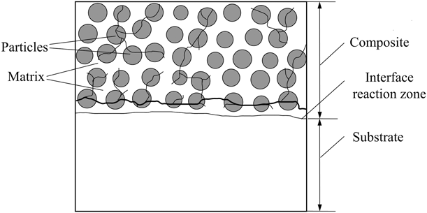
Figure 5 shows a schematic of the crack distribution in the surface composite. The micro-cracks initiated preferentially at the IRZ; then, after passing through the entire particle, the cracks propagated into the matrix and connected to one another. Because there is a large CTE mismatch not only between the particle and the matrix (IRZ) but also between the composite and the substrate (TL), the tungsten carbide particles near the TL were subjected to a much larger thermal stress compared with other areas of the composite. Thus, cracks had a greater tendency to initiate and propagate there, which explains why more numerous and wider cracks were observed at the TL, as shown in Fig. 2(d). During the thermal shock cycles, cracks in the particles continued to propagate until finally connecting to form much wider macro-cracks along the TL that eventually passed through the entire surface composite. Therefore, the TL is the weak link in the surface composite during thermal shock cycling. In addition, thermal stress can be produced and accumulate at the interface extremely easily, which has important effects on the thermal fatigue behavior of surface composites.
Schematic of the crack distribution in the surface composite.

Stress calculation
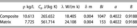
The chilling process of the thermal shock cycle is simplified as one-dimensional flat plate heat conduction, and the relevant thermodynamic data are listed in Table I.
Thermodynamic data.

Using the Fourier transform, the one-dimensional temperature field equation can be expressed as follows:
 $${{\theta \left( {\eta ,\tau } \right)} \over {{\theta _0}}} = - {{2\;\sin \;{\mu _1}} \over {{\mu _1} + \;\sin \;{\mu _1}\;\cos \;{\mu _1}}}\exp \left( {\mu _{\rm{r}}^2{F_0}} \right)\quad ,$$
 $$\mu _1^2 = {\left( {a + {b \over {Bi}}} \right)^{ - 1}}\quad ,$$
 $$Bi = {{h\delta } \over \lambda }\quad ,$$
 $${\theta _0} = \theta \left( {x,0} \right) = t\left( {x,0} \right) - {t_\infty }\quad ,$$
 $${F_0} = {{\lambda \tau } \over {\rho {c_{\rm{p}}}{\delta ^2}}}\quad .$$
where τ is the cooling time, δ is the plate thickness, Bi is the eigenvalue, h is the interface heat transfer coefficient, λ is the thermal conductivity of the plate, a and b are the calculation coefficients of μ1, t 0 is the initial temperature, t ∞ is the initial temperature of the cooling water, C p is the average thermal conductivity, and ρ is the density of the material.
The initial temperatures of the sample and cooling water are 500 and 20 °C, respectively, and θ0 is 480 °C. Based on the data in Table I and substituting Eqs. (2)–(5) into Eq. (1), the temperature field functions for the composite and substrate can be defined as follows:
 $$t{\left( {\delta ,\tau } \right)_{\rm{c}}} = 16.464\;\exp \left( {10.03\tau } \right)\quad ,$$
 $$t{\left( {\delta ,\tau } \right)_{\rm{s}}} = 16.464\;\exp \left( {8.16\tau } \right)\quad .$$
According to Eqs. (6) and (7), the cooling time from 500 to 20 °C for the composite is 0.339 s, while the cooling time from 500 to 20 °C for the substrate is 0.416 s, which will cause the thermal strain difference between the composite and substrate to be aggravated.
Therefore, at the TL, the cooling process consists of two stages.
In the first stage,
 $${\varepsilon _{\rm{c}}} = \int_0^{0.339} {{\alpha _{\rm{c}}}T{}_{\rm{c}}{\rm{d}}t} \quad ,$$
 $$\varepsilon _{\rm{s}}^\prime = \int_0^{0.339} {{\alpha _{\rm{m}}}T{}_{\rm{m}}{\rm{d}}t} \quad .$$
In the second stage,
 $${\varepsilon ''_{\rm{s}}} = \int_{0.339}^{0.416} {{\alpha _{\rm{m}}}T{}_{\rm{m}}{\rm{d}}t} \quad .$$
Here, εc is the deformation of the composite,  $\varepsilon _{\rm{s}}^\prime$ is the deformation of the matrix in the first stage, and
 ${\varepsilon ''_{\rm{s}}}$ is the deformation of the matrix in the second stage. It was obtained that the deformation of the composite in the first stage was 0.53%, and the deformation of the substrate was 0.35%; in the second stage, the composite had already reached room temperature, and the deformation of the substrate increased to 0.68%. This indicates that the maximum deformation difference, which was 0.18%, occurred in the first stage, meaning the stress is highest at the TL between the composite and the substrate. The maximum stress at the TL, 63.4 MPa, was then obtained using Hooke’s law.
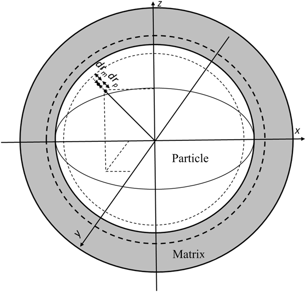
At the IRZ, there is also a thermal strain difference between the particles and the matrix. Figure 6 shows the stress model of the IRZ during the cooling process. The cast tungsten carbide particle is approximately spherical, and only the deformation along the radius of the sphere is considered. The deformation of the particle was determined to be 0.25%, while the deformation of the matrix was 0.56%; the total deformation at the interface was 0.81%, and thus cracks are prone to initiate at the IRZ. Using Hooke’s law, the maximum stress at the IRZ during cooling was 38 MPa.
Stress model of the IRZ during the cooling process.

These calculations indicate that because of the deformation at the interface, the stress values at the TL and IRZ (63.4 and 38 MPa, respectively) were higher than those at other areas. Thermal stress was thus prone to generate and accumulate at the IRZ and TL, leading to crack initiation at those locations. Because the stress at the TL was highest, and part of the tungsten carbide particles were located near the TL, the rate of crack initiation increased in this area, and the cracks propagated rapidly. After the initiation of micro-cracks at the IRZ, they propagated rapidly along the TL to form marco-cracks. Therefore, more and wider cracks were observed in the TL, as shown in Fig. 2(d).
Conclusions
In summary, the thermal fatigue behavior of cast tungsten carbide particle/steel matrix surface composites was investigated through thermal shock tests. Analysis of the experimental results allows the following conclusions to be drawn:
(1) With increasing thermal shock cycles, cracks preferentially initiated at the IRZ and then propagated rapidly to the interior of the particles until they had passed through the entire particle. Finally, the cracks near the IRZ connected to form macro-cracks along the TL and passed completely through the surface composite.
(2) Based on the stress analysis, the maximum thermal stress at the TL was calculated to be 63.4 MPa, while that at the IRZ was 38 MPa. The highest stress occurs in the TL, which is the weak link under thermal fatigue. The calculations were found to be in good agreement with the experimental results.
Materials and methods
Preparation of composites
Cast tungsten carbide particles were used as the reinforcement, and their chemical composition is listed in Table II. The cast tungsten carbide was composed of W2C, WC, and free carbon. The volume fraction of W2C–WC eutectoids was at least 74.7% [Reference Chen, Meredith, Dickey and Trice27], accounting for the majority of the particle. High Cr carbon steel was used as the substrate, and its chemical composition is given in Table III. The high Cr steel had good oxidation resistance, with a Cr content of 15.0–15.2 wt%.
Chemical composition of cast tungsten carbide (wt%).

Composition of the high Cr steel (wt%).

The cast tungsten carbide particle/steel matrix surface composites were prepared using the V-EPC infiltration technique. Figure 1(a) shows a schematic of the V-EPC infiltration principle, which can be summarized as comprising the following three steps [Reference Li, Jiang, Zhou, Lu and Zhou28]. First, the EPS pattern was fabricated, and the EPS gating system and mold cavity were glued together using an adhesion agent. By paving with a 95:4:1 vol% mixture of cast tungsten carbide particles (particle size of 0.38–0.55 mm), polyvinyl alcohol solution, and foaming agent, respectively, the preform layer was formed on the underside of the mold cavity; it was then dried at 50 °C. The entire mold was then placed into a water-based casting coating to form a thickness of 1 mm and dried at 70 °C for 6 h. Second, the EPC sand mold was fabricated. The sand box containing the EPS mold was filled with dry quartz sand (0.2–0.3 mm) and placed on a vibrating table to tighten the sand; however, the mold had good permeability. Third, casting infiltration was used to obtain the composites. Molten metal was poured into the EPS pattern. The composite was formed as melted high Cr carbon steel infiltrated the preform layer, as shown in Fig. 1(b).
Characterization
The microstructure of the samples was analyzed using scanning electron microscopy (SEM; VEGA 3 SBH, TESCAN, Brno, Czech Republic) combined with energy-dispersive X-ray spectroscopy (EDS; GENESIS, EDAX, Mahwah, New Jersey). The thermal expansion coefficient of the sintered samples was measured using a thermal expansion tester (DIL402PC, NETZSCH Co., Germany). The thermal conductivity of the samples was evaluated with a flash thermal conductivity meter (LFA 447 Nano flash®, NETZSCH Co.) which was able to synchronize the thermal diffusion coefficient (alpha) and the heat (C p).
The thermal fatigue behavior of the surface composites was analyzed through thermal shock tests. Samples were cut from the surface composite with geometric dimensions of 25 × 20 × 8 mm, and from the composite on the surface with dimensions of 20 × 8 mm. Samples were then placed in a chamber furnace at 500 °C for 5 min and quickly quenched in cold water. After 1 min, they were drained and brought to room temperature. The operation was repeated to observe the fatigue behavior of the material.
Author contributions
The experiments were designed by Zulai Li, Quan Shan, and Donglan Zhang, and carried out by Quan Shan and Donglan Zhang. The composites were fabricated by Zulai Li. The thermal shock tests were performed by Zulai Li and Donglan Zhang. The manuscript was written by Zulai Li, Donglan Zhang, and Quan Shan. Zulai Li and Donglan Zhang contributed equally to the article, and Zulai Li and Donglan Zhang are the corresponding authors of this research article.
Acknowledgments
The authors acknowledge the funding support from the National Natural Science Foundation of China (51561018 and 51871116).