



1 Introduction
In a wide context, water entry refers to that in which a solid body penetrates through the free surface of a liquid at large relative speed, in the sense of either the body moving towards the liquid or the other way round. This problem has a wide range of applications in many engineering fields. Slamming of marine vehicles, impact of green water on ship decks or offshore platforms and extreme waves including tsunamis on the coastline are well-known examples (Faltinsen Reference Faltinsen2005). Impact is typically characterized by a short duration, during which velocity and the free surface shape change rapidly both temporally and spatially. It may generate high pressure peaks and large pressure gradients. The severe fluid loading on the structure can lead to its damage or even destruction.
Water-entry problems have been extensively investigated using wedge geometry. In addition to direct applications of its results to improve the design of ship hulls, half-submerged propellers, high-speed planing boats and seaplanes etc., the investigations of such a geometry can also reveal some important features and provide better understanding of fluid flows in more general situations. When a symmetric wedge enters a horizontal water surface vertically, the generated flow will be also symmetric, and no flow will cross the tip of the wedge. In other cases, including asymmetric wedges or oblique entries, the cross-flow will occur at the tip of the wedge and the physics of the flow will be changed. Experiments done by Judge, Troesch & Perlin (Reference Judge, Troesch and Perlin2004) revealed that, under certain conditions, flow detachment can occur, and this could change flow features completely, especially in the local area. Another important effect of flow asymmetry is that a vortex sheet is shed from the tip, which significantly changes the configuration of the flow near the apex. As in the case without a free surface (Pullin Reference Pullin1978; Xu Reference Xu.2016), the shed vortex leads to the formation of a recirculation region. These aspects are expected to have some important consequences, especially in the area near the wedge apex. However, these effects have not been carefully considered in the previous works on water entry and they are the main purpose of the present study.
There is a large body of work on water entry of a wedge without taking account of vortex shedding. The theories based on the incompressible velocity potential for solid-body impact with a liquid were first proposed by von Karman (Reference von Karman1929) and Wagner (Reference Wagner1932). The former assumed an undisturbed free surface while the latter introduced a correction for the contact point of the body surface and the free surface. Many practical problems have been solved on the basis of these theories. A particular feature in the Wagner theory is that a body is usually replaced by an equivalent plate. The width of the plate is obtained from the horizontal distance between the two contact points of the body with the free surface. This changes with time and needs to be found as part of the solution. The Wagner theory has been found to be very effective in many cases. However, it predicts an infinite velocity and pressure at the contact point and a jet is usually absent. This drawback has been corrected in further development of the Wagner theory in the framework of the matched asymptotic method. Various impact problems have then been solved through this method by Armand & Cointe (Reference Armand and Cointe1987), Howison, Ockendon & Wilson (Reference Howison, Ockendon and Wilson1991), Korobkin & Puknachov (Reference Korobkin and Puknachov1988), Korobkin (Reference Korobkin2004), Howison, Ockendon & Oliver (Reference Howison, Ockendon and Oliver2004) and Oliver (Reference Oliver2007). A different modification for the conventional Wagner theory is to take into account the body shape and not to replace it with an equivalent plate as is done by Zhao, Faltinsen & Aarsnes (Reference Zhao, Faltinsen and Aarsnes1996) using a boundary-integral equation method and Mei, Liu & Yue (Reference Mei, Liu and Yue1999) using a conformal mapping technique.
Water-entry problem has also been solved based on a fully nonlinear model. For a wedge at constant entry speed, when the flow is assumed to be potential, gravity and surface tension effects are ignored, the problem becomes self-similar. Mathematically, the temporal variable can be incorporated into the spatial variables. The boundary conditions on the unknown free surface no longer involve explicitly time but they remain fully nonlinear. The complete solution for such a formulation was obtained by Dobrovol’skaya (Reference Dobrovol’skaya1969) for a symmetric wedge entering the free surface vertically. Chekin (Reference Chekin1989) generalized Dobrovol’skaya’s approach to the problems of oblique water entry of a wedge and an inclined flat plate. More recently, this problem was considered by Semenov & Iafrati (Reference Semenov and Iafrati2006) and Semenov & Yoon (Reference Semenov and Yoon2009), Semenov & Wu (Reference Semenov and Wu2012) using integral hodograph method (IHM), and by Iafrati (Reference Iafrati2000) and Xu, Duan & Wu (Reference Xu, Duan and Wu2008, Reference Xu, Duan and Wu2010) using a numerical method. In all these works, the streamline from the tip is attached to the wedge surface and no vortex shedding is taken into account. As a result, a singularity in velocity and pressure at the wedge apex appeared. This is obviously a consequence of the pure irrotational flow assumption. In real fluids, the streamline will not bend over the corner. Instead, it will separate from the tip and create a recirculation region. This is obviously due to the viscous effect which is not included in the pure irrotational flow. In order to resolve the velocity singularity at the tip Chekin (Reference Chekin1989) proposed a model with a cavity at the tip, however, no numerical results were provided. Riccardi & Iafrati (Reference Riccardi and Iafrati2004) included a pointed vortex shedding from the apex of the wedge during water entry. However, the free surface was kept flat and the potential on the free surface remained at zero.
In the present study we address the problem of asymmetric water entry of a wedge with attached flow on the leeward side and vortex shedding from the wedge apex. The problem is solved within certain ranges of the wedge heel angle and the direction of the incoming velocity relative to the body, confined by some constraints. The first constraint is an obvious geometrical one, which requires that the deadrise angles on both sides of the wedge are positive, or the wedge surface is not in touch with water before the wedge apex. The second one is that the angle between the incoming flow direction and the leeward side of the wedge should not exceed a critical value. Beyond this critical value the liquid will no longer be in touch with the surface of the leeward side, or the flow becomes detached, as was observed in the experiment by Judge et al. (2004). Within these constraints a mathematical model with fully nonlinear free surface conditions at their exact position together with vortex shedding from the wedge apex is adopted. The vortex shedding is considered in the form of a vortex sheet, or vortex line in the present two-dimensional case, starting from the wedge apex. The tangential velocity across the vortex line is discontinuous. The total complex velocity potential is split into two components. The first one is principally about the irrotational flow generated by the body motion during water entry. The IHM developed previously for free-surface flows (Semenov & Wu Reference Semenov and Wu2012) without a vortex is used. However, such a solution alone leads to a singularity at the wedge apex. Thus the second part of the solution is due to the vortex sheet started from the wedge apex. The method for the vortex sheet follows the formulation of Moore (Reference Moore1975), whose detailed application to a wedge without the free surface was made by Pullin (Reference Pullin1978). Unlike the work of Pullin, however, the incoming flow to the wedge here is not a prescribed one but is the one due to water entry. Due to the nonlinearity of the boundary condition, these two components of the problem cannot be solved separately, and they have to be solved simultaneously. In particular, using the dynamic and kinematic boundary conditions on the free surface, the problem is reduced to a system of an integral and an integro-differential equation in the parameter plane, in terms of the velocity magnitude and the velocity angle to the fluid boundary, respectively. The motion of the vortex sheet is governed by the Birkhoff–Rott (B–R) integro-differential equation (Rott Reference Rott1956; Birkhoff Reference Birkhoff1962), which expresses the fact that the points of the vortex sheet move with the induced fluid velocity and the circulation corresponding to each of these points remains unchanged. The coupled systems of equations from the free surface boundary conditions and B–R equation are then solved numerically through successive approximations.
In the following sections the derivation of the integro-differential equations based on the IHM and B–R equations are first presented, followed by the numerical method for solving these equations. Results are then provided, in particular near the wedge apex, through the streamlines, vortex sheet shape, size and location of the recirculation region and the pressure distribution along the wedge. The effects of the shedding vortex on the local flow and the free surface are then discussed, aiming to give some insights into the flow structure and pressure distribution near the wedge apex when the vortex shedding effect is included.
2 Formulation of the problem and the solution procedure
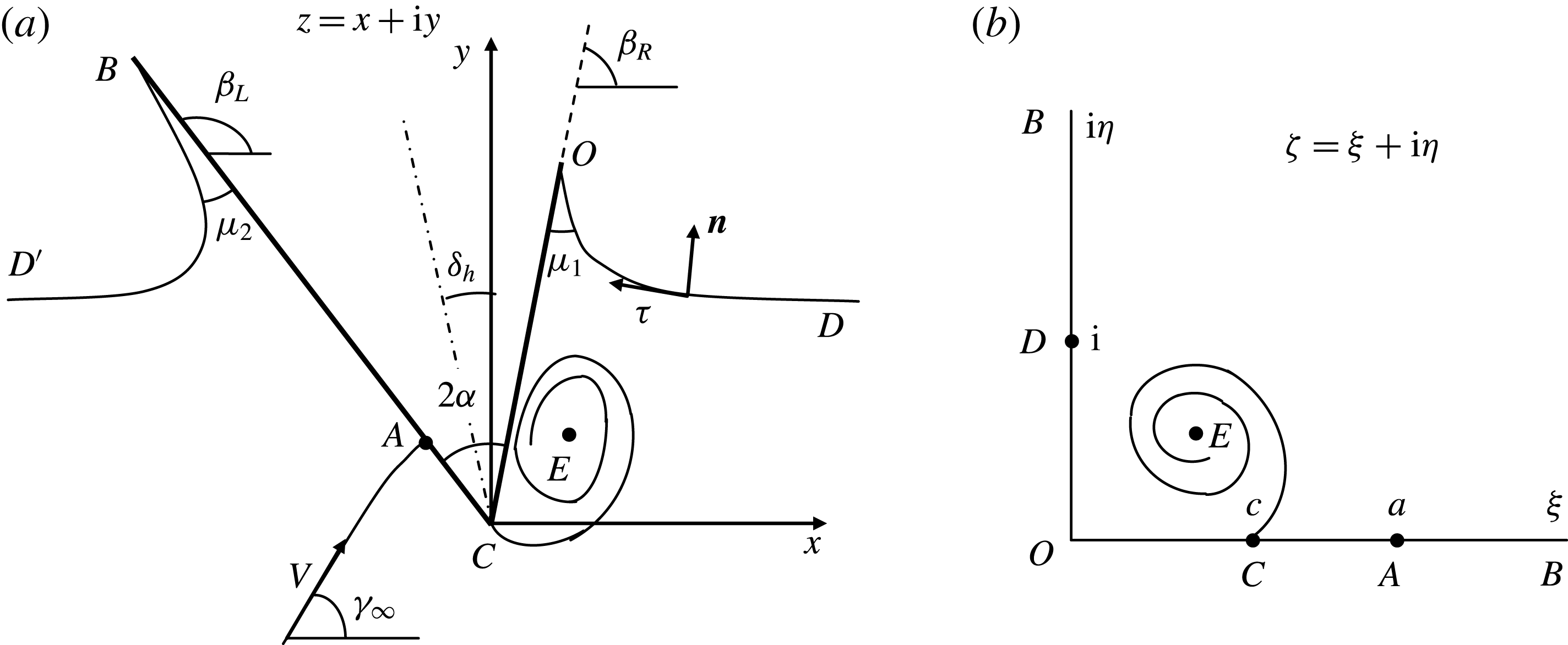
We consider the flow of an ideal incompressible fluid, generated by water entry of a wedge of inner angle
 $2\unicode[STIX]{x1D6FC}$
. Gravity and surface tension effects are neglected. The pressure on the free surface is assumed to be constant and equal to the atmospheric pressure
 $P_{a}$
. The definitions of the geometric parameters are shown in figure 1(a). The origin of the Cartesian coordinate system
 $xy$
is fixed at the wedge apex. The liquid is assumed to move toward the stationary solid wedge with velocity
 $V$
which forms an angle
 $\unicode[STIX]{x1D6FE}_{\infty }$
with the
 $x$
-axis. Then, the free-surface elevation at
 $x=\pm \infty$
approaches
 $Y_{\infty }=Vt\sin \unicode[STIX]{x1D6FE}_{\infty }$
. The symmetry line of the solid wedge forms a heel angle
 $\unicode[STIX]{x1D6FF}_{h}$
with the
 $y$
-axis. It follows from the geometry of the problem that the right and left sides of the solid wedge form angles
 $\unicode[STIX]{x1D6FD}_{R}=\unicode[STIX]{x03C0}/2-\unicode[STIX]{x1D6FC}+\unicode[STIX]{x1D6FF}_{h}$
and
 $\unicode[STIX]{x1D6FD}_{L}=\unicode[STIX]{x03C0}/2+\unicode[STIX]{x1D6FC}+\unicode[STIX]{x1D6FF}_{h}$
, respectively, with the
 $x$
-axis. The problem is symmetric only when
 $\unicode[STIX]{x1D6FE}_{\infty }=90^{\circ }$
and
 $\unicode[STIX]{x1D6FF}_{h}=0$
.
(a) Asymmetric water entry of a wedge: (a) similarity plane
 $z=x+\text{i}y$
; (b) the parameter plane.
Stagnation point
 $A$
is expected to appear on the windward side of the wedge, where the incoming zero streamline splits into two along the body surface, moving in opposite directions. In the case without a vortex sheet (Semenov & Wu Reference Semenov and Wu2012), when the flow moves towards the apex
 $C$
of the wedge, the liquid accelerates to an infinite speed and turns around the sharp corner. Then, it decelerates on the leeward side. Although such flow configuration is mathematically possible in an ideal fluid, it does not reflect the real physics locally. For a real liquid with viscosity, the boundary layer will lead to vorticities shed from the body and both the velocity and pressure at the apex will remain finite. To model this in an ideal liquid, a free shear layer starting from the apex can be introduced (Rott Reference Rott1956). Across the layer, the tangential velocity will be discontinuous. The vortex sheet will roll up into a spiral-like shape, as observed in the problem of an infinite wedge in an unbounded flow domain (Pullin Reference Pullin1978).
Here, we will consider the spiral vortex effect during water entry. The problem is self-similar since there is no length scale. Therefore, the time-dependent problem in the physical plane
 $Z=X+\text{i}Y$
can be written in the stationary plane
 $z=x+\text{i}y$
in terms of the self-similar variables
 $x=X/(Vt)$
and
 $y=Y/(Vt)$
, where
 $t$
is the time starting from the moment of impact. The complex velocity potential
 $W(Z,t)=\unicode[STIX]{x1D6F7}(Z,t)+\text{i}Y(Z,t)$
for the self-similar flow is written in the form
 $$\begin{eqnarray}\displaystyle W(Z,t)=V^{2}tw(z)=V^{2}t[\unicode[STIX]{x1D719}(x,y)+\text{i}\unicode[STIX]{x1D713}(x,y)], & & \displaystyle\end{eqnarray}$$
where
 $\unicode[STIX]{x1D719}(x,y)$
and
 $\unicode[STIX]{x1D713}(x,y)$
are the velocity potential and the streamfunction in the similarity plane. We may decompose the complex potential of such a flow into two components
 $$\begin{eqnarray}\displaystyle w(z)=w_{1}(z)+w_{2}(z), & & \displaystyle\end{eqnarray}$$
where
 $w_{1}(z)$
is the complex potential due to water entry without a vortex sheet and
 $w_{2}(z)$
is the complex potential due to the spiral vortex sheet. The complex potential
 $w_{1}(z)$
has a singularity at the apex of the wedge. Introduction of the complex potential
 $w_{2}(z)$
is to ensure that there will be no singularity in
 $w(z)$
, and the velocity at the apex will be finite. This means that a singularity at point
 $C$
exists in
 $w_{2}(z)$
, which has the same order as that in
 $w_{1}(z)$
.
2.1 General approach for solving free-surface problems
In order to determine the function
 $w(z)$
we introduce a parameter plane, or
 $\unicode[STIX]{x1D701}$
plane, as suggested by Joukovskii (Reference Joukovskii1890) and Michell (Reference Michell1890). Then, the complex velocity, or strictly speaking the conjugate of the complex velocity,
 $\text{d}w/\text{d}z$
, and the derivative of the complex potential,
 $\text{d}w/\text{d}\unicode[STIX]{x1D701}$
, are found as functions of the parameter
 $\unicode[STIX]{x1D701}$
in the form
 $$\begin{eqnarray}\displaystyle w(\unicode[STIX]{x1D701})=w(0)+\int _{0}^{\unicode[STIX]{x1D701}}\frac{\text{d}w}{\text{d}\unicode[STIX]{x1D701}}\,\text{d}\unicode[STIX]{x1D701},\quad z(\unicode[STIX]{x1D701})=z(0)+\left.\int _{0}^{\unicode[STIX]{x1D701}}\frac{\text{d}w}{\text{d}\unicode[STIX]{x1D701}}\right/\frac{\text{d}w}{\text{d}z}\,\text{d}\unicode[STIX]{x1D701}. & & \displaystyle\end{eqnarray}$$
Further development of this method was done by Chaplygin (see chap. 4 in Gurevich Reference Gurevich1965), who suggested analysis of the singular points of a complex function followed by finding the function using Liouville’s theorem, instead of using conformal mapping in an explicit form. We choose the first quadrant of the
 $\unicode[STIX]{x1D701}$
plane as the parameter region corresponding to the physical domain to derive expressions for the complex velocity,
 $\text{d}w/\text{d}z$
, and the derivative of the complex potential,
 $\text{d}w/\text{d}\unicode[STIX]{x1D701}$
, as functions of the variable
 $\unicode[STIX]{x1D701}=\unicode[STIX]{x1D709}+\text{i}\unicode[STIX]{x1D702}$
. Conformal mapping allows us to fix three points in the parameter region arbitrarily, which are chosen as
 $O$
,
 $B$
and
 $D$
in the present problem, as shown in figure 1(b). The first two are the intersections of the free surface with the body surface and the last one is at infinity. In this parameter plane, the positive imaginary axis (
 $\unicode[STIX]{x1D702}>0$
,
 $\unicode[STIX]{x1D709}=0$
) corresponds to the free surface, and the positive real axis (
 $\unicode[STIX]{x1D709}>0$
,
 $\unicode[STIX]{x1D702}=0$
) corresponds to the wetted part of the wedge. The points
 $\unicode[STIX]{x1D701}=a$
and
 $\unicode[STIX]{x1D701}=c$
are the images of the stagnation point
 $A$
and the wedge apex
 $C$
in the similarity plane, respectively. The values of
 $a$
and
 $c$
are not known and have to be determined as part of the solution.
According to (2.2), we may write
 $$\begin{eqnarray}\displaystyle & \displaystyle \frac{\text{d}w}{\text{d}z}=\frac{\text{d}w_{1}}{\text{d}z}+\frac{\text{d}w_{2}}{\text{d}z}=\frac{\text{d}w_{1}}{\text{d}z}F(z), & \displaystyle\end{eqnarray}$$
 $$\begin{eqnarray}\displaystyle & \displaystyle \frac{\text{d}w}{\text{d}\unicode[STIX]{x1D701}}=\frac{\text{d}w_{1}}{\text{d}\unicode[STIX]{x1D701}}+\frac{\text{d}w_{2}}{\text{d}\unicode[STIX]{x1D701}}=\frac{\text{d}w_{1}}{\text{d}\unicode[STIX]{x1D701}}F(z), & \displaystyle\end{eqnarray}$$
where
 $$\begin{eqnarray}\displaystyle F(\unicode[STIX]{x1D701})=\left(1+\left.\frac{\text{d}w_{2}}{\text{d}z}\right/\frac{\text{d}w_{1}}{\text{d}z}\right)=\left(1+\left.\frac{\text{d}w_{2}}{\text{d}\unicode[STIX]{x1D701}}\right/\frac{\text{d}w_{1}}{\text{d}\unicode[STIX]{x1D701}}\right). & & \displaystyle\end{eqnarray}$$
This indicates that the potential
 $w_{1}$
is chosen as the reference potential, since
 $\text{d}w_{1}/\text{d}z$
and
 $\text{d}w_{1}/\text{d}\unicode[STIX]{x1D701}$
can be obtained from the solution of the problem without a vortex sheet (Semenov & Wu Reference Semenov and Wu2012). Moreover, from (2.4) and (2.5) it follows that the derivative of the mapping function,
 $$\begin{eqnarray}\displaystyle \frac{\text{d}z}{\text{d}\unicode[STIX]{x1D701}}=\left.\frac{\text{d}w}{\text{d}\unicode[STIX]{x1D701}}\right/\frac{\text{d}w}{\text{d}z}=\left.\frac{\text{d}w_{1}}{\text{d}\unicode[STIX]{x1D701}}\right/\frac{\text{d}w_{1}}{\text{d}z} & & \displaystyle\end{eqnarray}$$
is directly linked to the reference potential
 $w_{1}$
only.
In order to derive an expression for the derivative of the complex potential,
 $\text{d}w/\text{d}\unicode[STIX]{x1D701}$
, we analyse the behaviour of the velocity potential along the free surface. It is useful to introduce the unit vectors
 $\boldsymbol{n}$
and
 $\unicode[STIX]{x1D749}$
in the normal and tangential directions of the fluid boundary, respectively. The normal vector points out of the fluid region while the spatial arc length coordinate
 $s$
points along the surface and increases in the direction of
 $\unicode[STIX]{x1D749}$
, along which the fluid region is on the left (figure 1
a). With this notation,
 $$\begin{eqnarray}\displaystyle \text{d}w=(v_{s}+\text{i}v_{n})\,\text{d}s, & & \displaystyle\end{eqnarray}$$
where
 $v_{s}$
and
 $v_{n}$
are the tangential and normal velocity components, respectively. Let
 $\unicode[STIX]{x1D703}$
be the angle between the velocity vector on the surface and
 $\unicode[STIX]{x1D749}$
, which means
 $\unicode[STIX]{x1D703}=\arg (v_{s}+\text{i}v_{n})$
. Taking the magnitude of (2.4) and the argument of equation
 $$\begin{eqnarray}\displaystyle \frac{\text{d}w}{\text{d}s}=\frac{\text{d}w_{1}}{\text{d}s}+\frac{\text{d}w_{2}}{\text{d}s}=\frac{\text{d}w_{1}}{\text{d}s}F(\unicode[STIX]{x1D701}), & & \displaystyle\end{eqnarray}$$
we can obtain
 $$\begin{eqnarray}\displaystyle & \displaystyle v(\unicode[STIX]{x1D702})=\left|\frac{\text{d}w}{\text{d}z}\right|_{\unicode[STIX]{x1D701}=\text{i}\unicode[STIX]{x1D702}}=v_{1}(\unicode[STIX]{x1D702})v_{F}(\unicode[STIX]{x1D702}), & \displaystyle\end{eqnarray}$$
 $$\begin{eqnarray}\displaystyle & \displaystyle \unicode[STIX]{x1D703}(\unicode[STIX]{x1D702})=\arg \left(\frac{\text{d}w}{\text{d}s}\right)=\arg \left(\frac{\text{d}w_{1}}{\text{d}s}\right)+\arg [F(\unicode[STIX]{x1D701})_{\unicode[STIX]{x1D701}=\text{i}\unicode[STIX]{x1D702}}]=\unicode[STIX]{x1D703}_{1}(\unicode[STIX]{x1D702})+\unicode[STIX]{x1D703}_{F}(\unicode[STIX]{x1D702}), & \displaystyle\end{eqnarray}$$
where
 $$\begin{eqnarray}\displaystyle \left.\begin{array}{@{}c@{}}\displaystyle v_{1}(\unicode[STIX]{x1D702})=\left|\frac{\text{d}w_{1}}{\text{d}z}\right|_{\unicode[STIX]{x1D701}=\text{i}\unicode[STIX]{x1D702}},\quad \unicode[STIX]{x1D703}_{1}(\unicode[STIX]{x1D702})=\arg \left(\frac{\text{d}w_{1}}{\text{d}s}\right)_{\unicode[STIX]{x1D701}=\text{i}\unicode[STIX]{x1D702}},\\ \displaystyle v_{F}(\unicode[STIX]{x1D702})=|F(\unicode[STIX]{x1D701})|_{\unicode[STIX]{x1D701}=\text{i}\unicode[STIX]{x1D702}},\quad \unicode[STIX]{x1D703}_{F}(\unicode[STIX]{x1D702})=\arg [F(\unicode[STIX]{x1D701})]_{\unicode[STIX]{x1D701}=\text{i}\unicode[STIX]{x1D702}}.\end{array}\right\} & & \displaystyle\end{eqnarray}$$
2.2 Complex potential due to water entry
The problem of the impact between the liquid wedge and solid wedge without a vortex sheet, in which a singularity exits at the wedge apex, has been solved by Semenov & Wu (Reference Semenov and Wu2012). There, the expressions for the complex velocity and the derivative of the complex potential as well as the mapping function
 $z=z(\unicode[STIX]{x1D701})$
were derived, and the flat free-surface problem was treated as a special case of a liquid wedge with an inner angle
 $\unicode[STIX]{x03C0}$
. In the present notation, the expression for the complex velocity,
 $\text{d}w_{1}/\text{d}z$
, takes the form
 $$\begin{eqnarray}\displaystyle \frac{\text{d}w_{1}}{\text{d}z}=v_{0}\left(\frac{\unicode[STIX]{x1D701}-a}{\unicode[STIX]{x1D701}+a}\right)\left(\frac{\unicode[STIX]{x1D701}+c}{\unicode[STIX]{x1D701}-c}\right)^{1-2\unicode[STIX]{x1D6FC}/\unicode[STIX]{x03C0}}\exp \left[-\frac{\text{i}}{\unicode[STIX]{x03C0}}\int _{0}^{\infty }\frac{\text{d}\ln v_{1}}{\text{d}\unicode[STIX]{x1D702}}\ln \left(\frac{\text{i}\unicode[STIX]{x1D702}-\unicode[STIX]{x1D701}}{\text{i}\unicode[STIX]{x1D702}+\unicode[STIX]{x1D701}}\right)\text{d}\unicode[STIX]{x1D702}-\text{i}\unicode[STIX]{x1D6FD}_{L}\right], & & \displaystyle \nonumber\\ \displaystyle & & \displaystyle\end{eqnarray}$$
where
 $v_{0}=v(\unicode[STIX]{x1D702})_{\unicode[STIX]{x1D702}=0}$
is the velocity magnitude at point
 $O$
. It can be clearly seen that the complex velocity has a singularity of the order of
 $(\unicode[STIX]{x1D701}-c)^{2\unicode[STIX]{x1D6FC}/\unicode[STIX]{x03C0}-1}$
at point
 $\unicode[STIX]{x1D701}=c$
which corresponds to the wedge apex. Through analysing the behaviour of the angle of the velocity,
 $\unicode[STIX]{x1D703}_{1}=\arg (v_{s}+\text{i}v_{n})$
, relative to the boundary, the derivative of the complex potential,
 $\text{d}w_{1}/\text{d}\unicode[STIX]{x1D701}$
, was obtained in the form
 $$\begin{eqnarray}\displaystyle \frac{\text{d}w_{1}}{\text{d}\unicode[STIX]{x1D701}}=K\unicode[STIX]{x1D701}^{2\unicode[STIX]{x1D707}_{1}/\unicode[STIX]{x03C0}-1}\frac{\unicode[STIX]{x1D701}^{2}-a^{2}}{(\unicode[STIX]{x1D701}+1)^{2}}\exp \left[\frac{1}{\unicode[STIX]{x03C0}}\int _{0}^{\infty }\frac{\text{d}\unicode[STIX]{x1D703}_{1}}{\text{d}\unicode[STIX]{x1D702}}\ln (\unicode[STIX]{x1D701}^{2}+\unicode[STIX]{x1D702}^{2})\,\text{d}\unicode[STIX]{x1D702}\right], & & \displaystyle\end{eqnarray}$$
where
 $K$
is a real factor.
From (2.13) and (2.14) the derivative of the mapping function can be obtained as
 $$\begin{eqnarray}\displaystyle \frac{\text{d}z}{\text{d}\unicode[STIX]{x1D701}} & = & \displaystyle \frac{K}{v_{0}}\unicode[STIX]{x1D701}^{2\unicode[STIX]{x1D707}_{1}/\unicode[STIX]{x03C0}-1}\frac{(\unicode[STIX]{x1D701}+a)^{2}}{(1+\unicode[STIX]{x1D701})^{2}}\left(\frac{\unicode[STIX]{x1D701}-c}{\unicode[STIX]{x1D701}+c}\right)^{1-2\unicode[STIX]{x1D6FC}/\unicode[STIX]{x03C0}}\exp \left[\frac{1}{\unicode[STIX]{x03C0}}\int _{0}^{\infty }\frac{\text{d}\unicode[STIX]{x1D703}_{1}}{\text{d}\unicode[STIX]{x1D702}}\ln (\unicode[STIX]{x1D702}^{2}+\unicode[STIX]{x1D701}^{2})\,\text{d}\unicode[STIX]{x1D702}\right.\nonumber\\ \displaystyle & & \displaystyle +\left.\frac{\text{i}}{\unicode[STIX]{x03C0}}\int _{0}^{\infty }\frac{\text{d}\ln v_{1}}{\text{d}\unicode[STIX]{x1D702}}\ln \left(\frac{\text{i}\unicode[STIX]{x1D702}-\unicode[STIX]{x1D701}}{\text{i}\unicode[STIX]{x1D702}+\unicode[STIX]{x1D701}}\right)\text{d}\unicode[STIX]{x1D702}+\text{i}\unicode[STIX]{x1D6FD}_{L}\right].\end{eqnarray}$$
Equations (2.13)–(2.15) contain the parameters
 $a$
,
 $c$
,
 $K$
and the functions
 $v_{1}(\unicode[STIX]{x1D702})$
and
 $\unicode[STIX]{x1D703}_{1}(\unicode[STIX]{x1D702})$
, which are to be determined from physical considerations and the dynamic and kinematic boundary conditions on the free surface. At infinity, the complex velocity tends to
 $\exp (-\text{i}\unicode[STIX]{x1D6FE}_{\infty })$
. Taking the argument of (2.4) and accounting for (2.13), we have
 $$\begin{eqnarray}\displaystyle \arg \left(\frac{\text{d}w}{\text{d}z}\right)_{\unicode[STIX]{x1D701}=\text{i}}=\arg \left(\frac{\text{d}w_{1}}{\text{d}z}\right)_{\unicode[STIX]{x1D701}=\text{i}}+\arg [F(\unicode[STIX]{x1D701})]_{\unicode[STIX]{x1D701}=\text{i}}=\arg \left(\frac{\text{d}w_{1}}{\text{d}z}\right)_{\unicode[STIX]{x1D701}=\text{i}}+\unicode[STIX]{x1D703}_{F}(\unicode[STIX]{x1D702})_{\unicode[STIX]{x1D702}=1}=-\unicode[STIX]{x1D6FE}_{\infty }. & & \displaystyle \nonumber\\ \displaystyle & & \displaystyle\end{eqnarray}$$
By letting
 $\unicode[STIX]{x1D701}=\text{i}$
in (2.13), which corresponds to infinity in the self-similar plane, the following equation is obtained
 $$\begin{eqnarray}\displaystyle & & \displaystyle -2\tan ^{-1}\frac{1}{a}+\left(2-\frac{4\unicode[STIX]{x1D6FC}}{\unicode[STIX]{x03C0}}\right)\tan ^{-1}\frac{1}{c}-\frac{1}{\unicode[STIX]{x03C0}}\int _{0}^{\infty }\frac{\text{d}\ln v_{1}}{\text{d}\unicode[STIX]{x1D702}}\ln \left|\frac{\unicode[STIX]{x1D702}-1}{\unicode[STIX]{x1D702}+1}\right|\text{d}\unicode[STIX]{x1D702}\nonumber\\ \displaystyle & & \displaystyle \quad +\,\unicode[STIX]{x1D703}_{F}(1)+\unicode[STIX]{x1D6FC}-\unicode[STIX]{x1D6FF}_{h}-\frac{\unicode[STIX]{x03C0}}{2}+\unicode[STIX]{x1D6FE}_{\infty }=0.\end{eqnarray}$$
In the physical plane, the wetted length of the right side of the wedge in the self-similar flow is
 $v_{0}Vt$
. The length of the segment
 $OC$
in the similarity plane is then
 $|z_{O}|=v_{0}$
. Hence, the following equation is obtained
 $$\begin{eqnarray}\displaystyle \int _{0}^{c}\left|\frac{\text{d}z}{\text{d}\unicode[STIX]{x1D701}}\right|_{\unicode[STIX]{x1D701}=\unicode[STIX]{x1D709}}\text{d}\unicode[STIX]{x1D709}=v_{0}. & & \displaystyle\end{eqnarray}$$
An additional condition is obtained by enforcing the fact that the
 $y$
-coordinates of the free surface on the right- and left-hand sides have to be the same at infinity. This gives
 $$\begin{eqnarray}\displaystyle \text{Im}\left(\oint _{\unicode[STIX]{x1D701}=\text{i}}\frac{\text{d}z}{\text{d}\unicode[STIX]{x1D701}}\,\text{d}\unicode[STIX]{x1D701}\right)=\text{Im}\left(\unicode[STIX]{x03C0}\text{i}\,\underset{\unicode[STIX]{x1D701}=\text{i}}{\text{Res}}\,\frac{\text{d}z}{\text{d}\unicode[STIX]{x1D701}}\right)=\text{Im}\left[\unicode[STIX]{x03C0}\text{i}\lim _{\unicode[STIX]{x1D701}\rightarrow \text{i}}\frac{\text{d}}{\text{d}\unicode[STIX]{x1D701}}\left(\frac{\text{d}z}{\text{d}\unicode[STIX]{x1D701}}(\unicode[STIX]{x1D701}-\text{i})^{2}\right)\right]=0. & & \displaystyle\end{eqnarray}$$
By taking into account (2.15) and performing the integration through the residue method we get
 $$\begin{eqnarray}\displaystyle -\left(\frac{\unicode[STIX]{x1D707}_{1}}{\unicode[STIX]{x03C0}}-1\right)-\frac{1}{1+a^{2}}+\frac{1}{\unicode[STIX]{x03C0}}\int _{0}^{\infty }\frac{\text{d}\unicode[STIX]{x1D703}_{1}}{\text{d}\unicode[STIX]{x1D702}}\frac{\text{d}\unicode[STIX]{x1D702}}{\unicode[STIX]{x1D702}^{2}-1}=0. & & \displaystyle\end{eqnarray}$$
From (2.17)–(2.20) the parameters
 $a$
,
 $c$
,
 $K$
can be found if the functions
 $v_{1}(\unicode[STIX]{x1D702})$
and
 $\unicode[STIX]{x1D703}_{1}(\unicode[STIX]{x1D702})$
are specified.
2.2.1 Dynamic boundary condition on the free surface
The Bernoulli equation in the physical plane linking point
 $O$
and an arbitrary point in the flow domain gives
 $$\begin{eqnarray}\displaystyle \left.\frac{\unicode[STIX]{x2202}\unicode[STIX]{x1D6F7}}{\unicode[STIX]{x2202}t}\right|_{Z}+\frac{V^{\prime 2}}{2}+\frac{P}{\unicode[STIX]{x1D71A}}=\left.\frac{\unicode[STIX]{x2202}\unicode[STIX]{x1D6F7}}{\unicode[STIX]{x2202}t}\right|_{Z=0}+\frac{V_{0}^{2}}{2}+\frac{P_{a}}{\unicode[STIX]{x1D71A}}, & & \displaystyle\end{eqnarray}$$
where
 $P$
and
 $V^{\prime }$
are the pressure and velocity at an arbitrary point of the fluid domain,
 $\unicode[STIX]{x1D71A}$
is the density of the liquid. By taking advantage of the self-similarity of the flow defined in (2.1), and using the spatial coordinate of arc length,
 $s=S/(Vt)$
, Semenov & Iafrati (Reference Semenov and Iafrati2006) reduced this equation to the following
 $$\begin{eqnarray}\displaystyle v_{\ast }^{2}-v^{2}-2(\unicode[STIX]{x1D719}-\unicode[STIX]{x1D719}_{\ast })+2\frac{\text{d}\unicode[STIX]{x1D719}}{\text{d}s}s=0. & & \displaystyle\end{eqnarray}$$
Here, the subscript
 $\ast$
together with
 $s=0$
refers to the intersection points
 $O$
and
 $B$
respectively for the right and left free surfaces. By taking the derivative of (2.22) with respect to
 $s$
, and using
 $\text{d}\unicode[STIX]{x1D719}/\text{d}s=v_{s}$
and
 $v_{s}=v\cos \unicode[STIX]{x1D703}$
, the following differential equation is obtained
 $$\begin{eqnarray}\displaystyle \frac{\text{d}\unicode[STIX]{x1D703}}{\text{d}s}=\frac{v+s\cos \unicode[STIX]{x1D703}}{s\sin \unicode[STIX]{x1D703}}\frac{\text{d}\ln v}{\text{d}s}. & & \displaystyle\end{eqnarray}$$
Multiplying both sides of (2.23) by
 $\text{d}s/\text{d}\unicode[STIX]{x1D702}$
and taking into account that
 $\unicode[STIX]{x1D703}(\unicode[STIX]{x1D702})=\unicode[STIX]{x1D703}_{1}(\unicode[STIX]{x1D702})+\unicode[STIX]{x1D703}_{F}(\unicode[STIX]{x1D702})$
,
 $v(\unicode[STIX]{x1D702})=v_{1}(\unicode[STIX]{x1D702})v_{F}(\unicode[STIX]{x1D702})$
, we obtain the following integro-differential equation:
 $$\begin{eqnarray}\displaystyle \frac{\text{d}\unicode[STIX]{x1D703}_{1}}{\text{d}\unicode[STIX]{x1D702}}=\frac{v_{1}v_{F}+s\cos (\unicode[STIX]{x1D703}_{1}+\unicode[STIX]{x1D703}_{F})}{s\sin (\unicode[STIX]{x1D703}_{1}+\unicode[STIX]{x1D703}_{F})}\left(\frac{\text{d}\ln v_{1}}{\text{d}\unicode[STIX]{x1D702}}+\frac{\text{d}\ln v_{F}}{\text{d}\unicode[STIX]{x1D702}}\right)-\frac{\text{d}\unicode[STIX]{x1D703}_{F}}{\text{d}\unicode[STIX]{x1D702}}. & & \displaystyle\end{eqnarray}$$
where the arc length coordinate
 $s=s(\unicode[STIX]{x1D702})$
can be obtained by integrating (2.15)
 $$\begin{eqnarray}\displaystyle s(\unicode[STIX]{x1D702}) & = & \displaystyle -\int _{0}^{\unicode[STIX]{x1D702}}\left|\frac{\text{d}z}{\text{d}\unicode[STIX]{x1D701}}\right|_{\unicode[STIX]{x1D701}=\text{i}\unicode[STIX]{x1D702}^{\prime }}\,\text{d}\unicode[STIX]{x1D702}^{\prime }=-K\int _{0}^{\unicode[STIX]{x1D702}}\frac{\unicode[STIX]{x1D702}^{\prime (2\unicode[STIX]{x1D707}_{1}-1)}}{v_{1}(\unicode[STIX]{x1D702}^{\prime })}\frac{\unicode[STIX]{x1D702}^{\prime 2}+a^{2}}{(1-\unicode[STIX]{x1D702}^{\prime 2})^{2}}\nonumber\\ \displaystyle & & \displaystyle \times \,\exp \left[\frac{1}{\unicode[STIX]{x03C0}}\int _{0}^{\infty }\frac{\text{d}\unicode[STIX]{x1D703}_{1}}{\text{d}\unicode[STIX]{x1D702}^{\prime \prime }}\ln |\unicode[STIX]{x1D702}^{\prime \prime 2}-\unicode[STIX]{x1D702}^{\prime 2}|\,\text{d}\unicode[STIX]{x1D702}^{\prime \prime }\right]\text{d}\unicode[STIX]{x1D702}^{\prime },\quad 0<\unicode[STIX]{x1D702}<1,\end{eqnarray}$$
for the free surface on the right-hand side and
 $$\begin{eqnarray}\displaystyle s(\unicode[STIX]{x1D702})=\int _{\unicode[STIX]{x1D702}}^{\infty }\left|\frac{\text{d}z}{\text{d}\unicode[STIX]{x1D701}}\right|_{\unicode[STIX]{x1D701}=\text{i}\unicode[STIX]{x1D702}^{\prime }}\text{d}\unicode[STIX]{x1D702}^{\prime },\quad 1<\unicode[STIX]{x1D702}<\infty , & & \displaystyle\end{eqnarray}$$
for the free surface on the left-hand side.
2.2.2 Kinematic boundary condition on the free surface
The kinematic boundary condition in terms of the velocity magnitude
 $v$
and angle
 $\unicode[STIX]{x1D6FD}=-\!\arg (\text{d}w/\text{d}z)$
for this kind of self-similar flow problem has the following form (Semenov & Iafrati Reference Semenov and Iafrati2006)
 $$\begin{eqnarray}\displaystyle \frac{1}{\tan \unicode[STIX]{x1D703}}\frac{\text{d}\ln v}{\text{d}s}=\frac{\text{d}}{\text{d}s}\left[\arg \left(\frac{\text{d}w}{\text{d}z}\right)\right|. & & \displaystyle\end{eqnarray}$$
This equation is obtained using the fact that the acceleration of the fluid particle is orthogonal to the free boundary of constant pressure. Substituting the complex velocity in (2.13) into (2.27) and multiplying both sides of the result by
 $\text{d}s/\text{d}\unicode[STIX]{x1D702}=|\text{d}z/\text{d}\unicode[STIX]{x1D701}|_{\unicode[STIX]{x1D701}=\text{i}\unicode[STIX]{x1D702}}$
, the following integral equation for the function
 $\text{d}\ln v_{1}/\text{d}\unicode[STIX]{x1D702}$
is obtained
 $$\begin{eqnarray}\displaystyle & & \displaystyle -\frac{1}{\tan (\unicode[STIX]{x1D703}_{1}+\unicode[STIX]{x1D703}_{F})}\frac{\text{d}\ln v_{1}}{\text{d}\unicode[STIX]{x1D702}}+\frac{1}{\unicode[STIX]{x03C0}}\int _{0}^{\infty }\frac{\text{d}\ln v_{1}}{\text{d}\unicode[STIX]{x1D702}^{\prime }}\frac{2\unicode[STIX]{x1D702}^{\prime }}{{\unicode[STIX]{x1D702}^{\prime }}^{2}-\unicode[STIX]{x1D702}^{2}}\,\text{d}\unicode[STIX]{x1D702}^{\prime }\nonumber\\ \displaystyle & & \displaystyle \quad =\frac{1}{\tan (\unicode[STIX]{x1D703}_{1}+\unicode[STIX]{x1D703}_{F})}\frac{\text{d}\ln v_{F}}{\text{d}\unicode[STIX]{x1D702}}-\frac{\text{d}\unicode[STIX]{x1D703}_{F}}{\text{d}\unicode[STIX]{x1D702}}+\frac{2a}{a^{2}+\unicode[STIX]{x1D702}^{2}}+\left(\frac{2\unicode[STIX]{x1D6FC}}{\unicode[STIX]{x03C0}}-1\right)\frac{2c}{c^{2}+\unicode[STIX]{x1D702}^{2}}.\end{eqnarray}$$
The integral equations (2.24) and (2.28) together with equations (2.17), (2.18) and (2.20) make it possible to determine the functions
 $\unicode[STIX]{x1D703}_{1}(\unicode[STIX]{x1D702})$
and
 $v_{1}(\unicode[STIX]{x1D702})$
, and the parameters
 $a$
,
 $c$
and
 $K$
if the functions
 $\unicode[STIX]{x1D703}_{F}(\unicode[STIX]{x1D702})$
and
 $v_{F}(\unicode[STIX]{x1D702})$
are known. Once these functions are found, the contact angles between the wedge sides and the free surface,
 $\unicode[STIX]{x1D707}_{1}$
and
 $\unicode[STIX]{x1D707}_{2}$
, can be determined as follows:
 $$\begin{eqnarray}\displaystyle \unicode[STIX]{x1D707}_{1}=\lim _{\unicode[STIX]{x1D702}\rightarrow 0}\unicode[STIX]{x1D703}_{1}(\unicode[STIX]{x1D702}),\quad \unicode[STIX]{x1D707}_{2}=\unicode[STIX]{x03C0}-\lim _{\unicode[STIX]{x1D702}\rightarrow \infty }\unicode[STIX]{x1D703}_{1}(\unicode[STIX]{x1D702}). & & \displaystyle\end{eqnarray}$$
The former is explicitly required in the expression for the derivative of the complex potential in (2.14).
2.3 Complex potential of the vortex sheet
We consider the vortex sheet as a cut in the fluid domain. The liquid on both sides of the cut has the same normal velocity component but the tangential components are different. Similar to that proposed by Moore (Reference Moore1975), we describe the position of the vortex sheet in the similarity plane by a complex function
 $Z_{0}(\unicode[STIX]{x1D6E4},t)$
, where
 $\unicode[STIX]{x1D6E4}$
is the circulation obtained by integration of the vortex strength from the centre of the spiral (point
 $E$
in figure 1
a) to point
 $Z_{0}$
, and
 $\unicode[STIX]{x1D6E4}=\unicode[STIX]{x1D6E4}_{C}$
at point
 $C$
is the total circulation. This formulation has made use of the fact that point
 $Z_{0}$
can be written as a function of
 $\unicode[STIX]{x1D6E4}$
, as when
 $Z_{0}$
is followed, since
 $\text{d}\unicode[STIX]{x1D6E4}/\text{d}t=0$
(e.g. p. 30, Saffman Reference Saffman1993), or
 $Z_{0}$
always corresponds to the same
 $\unicode[STIX]{x1D6E4}$
. We may introduce the parameter
 $\unicode[STIX]{x1D706}=1-\unicode[STIX]{x1D6E4}/\unicode[STIX]{x1D6E4}_{C}$
which changes from
 $\unicode[STIX]{x1D706}=0$
at point
 $C$
to
 $\unicode[STIX]{x1D706}=1$
at point
 $E$
. Then, the vortex sheet in the similarity plane can be written as
 $z_{0}(\unicode[STIX]{x1D706})=Z_{0}/(Vt)$
. The line
 $\unicode[STIX]{x1D701}_{0}(\unicode[STIX]{x1D706})$
is the image of the vortex sheet
 $z_{0}(\unicode[STIX]{x1D706})$
in the parameter plane.
We will build such an expression for the complex potential
 $w_{2}(\unicode[STIX]{x1D701})$
whose imaginary part equals zero along the real and imaginary axes of the parameter plane. Then, the normal velocity due to
 $w_{2}(\unicode[STIX]{x1D701})$
on the fluid boundary is zero, which means that the required impermeable condition on the wedge surface is satisfied.
A concentrated vortex of circulation
 $\unicode[STIX]{x1D6FE}^{\ast }$
at point
 $\unicode[STIX]{x1D701}_{0}=\unicode[STIX]{x1D709}_{0}+\text{i}\unicode[STIX]{x1D702}_{0}$
in the parameter plane creates the logarithmic complex potential
 $w^{\ast }(\unicode[STIX]{x1D701},\unicode[STIX]{x1D701}_{0})=\unicode[STIX]{x1D6FE}^{\ast }/(2\unicode[STIX]{x03C0}\text{i})\ln (\unicode[STIX]{x1D701}-\unicode[STIX]{x1D701}_{0})$
. Due to the simple geometry of the parameter region, we can obtain the potential
 $w_{total}^{\ast }(\unicode[STIX]{x1D701},\unicode[STIX]{x1D701}_{0})$
, which has constant imaginary part along the positive real and imaginary axes, by adding the image vortexes of the same strength at points
 $-\unicode[STIX]{x1D701}_{0}$
,
 $\overline{\unicode[STIX]{x1D701}_{0}}$
and
 $-\overline{\unicode[STIX]{x1D701}_{0}}$
, or
 $$\begin{eqnarray}\displaystyle w_{total}^{\ast }(\unicode[STIX]{x1D701},\unicode[STIX]{x1D701}_{0})=w^{\ast }(\unicode[STIX]{x1D701},\unicode[STIX]{x1D701}_{0})+w^{\ast }(\unicode[STIX]{x1D701},-\unicode[STIX]{x1D701}_{0})+w^{\ast }(\unicode[STIX]{x1D701},\overline{\unicode[STIX]{x1D701}_{0}})+w^{\ast }(\unicode[STIX]{x1D701},-\overline{\unicode[STIX]{x1D701}_{0}}). & & \displaystyle\end{eqnarray}$$
For vortex distribution
 $\unicode[STIX]{x1D6FE}^{\prime }$
along a segment
 $\text{d}s$
,
 $\unicode[STIX]{x1D6FE}^{\ast }$
in the above equation can be replaced by
 $\unicode[STIX]{x1D6FE}^{\prime }\,\text{d}s$
. Following this principle, for a sheet with varying strength, the complex potential can be written as
 $$\begin{eqnarray}\displaystyle w_{2}(\unicode[STIX]{x1D701})=-\frac{J}{2\unicode[STIX]{x03C0}\text{i}}\int _{0}^{1}\{\ln [\unicode[STIX]{x1D701}-\unicode[STIX]{x1D701}_{0}(\unicode[STIX]{x1D706})]-\ln [\unicode[STIX]{x1D701}-\overline{\unicode[STIX]{x1D701}_{0}}(\unicode[STIX]{x1D706})]-\ln [\unicode[STIX]{x1D701}+\overline{\unicode[STIX]{x1D701}_{0}}(\unicode[STIX]{x1D706})]+\ln [\unicode[STIX]{x1D701}+\unicode[STIX]{x1D701}_{0}(\unicode[STIX]{x1D706})]\}\,\text{d}\unicode[STIX]{x1D706} & & \displaystyle \nonumber\\ \displaystyle & & \displaystyle\end{eqnarray}$$
in which
 $\text{d}\unicode[STIX]{x1D706}=-\unicode[STIX]{x1D6FE}^{\prime }\text{d}s$
has been used and therefore the integration is performed with respect to
 $\unicode[STIX]{x1D706}$
. This gives
 $$\begin{eqnarray}\displaystyle \frac{\text{d}w_{2}}{\text{d}\unicode[STIX]{x1D701}}=-\frac{J}{2\unicode[STIX]{x03C0}\text{i}}\int _{0}^{1}\left(\frac{1}{\unicode[STIX]{x1D701}-\unicode[STIX]{x1D701}_{0}(\unicode[STIX]{x1D706})}-\frac{1}{\unicode[STIX]{x1D701}-\overline{\unicode[STIX]{x1D701}_{0}}(\unicode[STIX]{x1D706})}-\frac{1}{\unicode[STIX]{x1D701}+\overline{\unicode[STIX]{x1D701}_{0}}(\unicode[STIX]{x1D706})}+\frac{1}{\unicode[STIX]{x1D701}+\unicode[STIX]{x1D701}_{0}(\unicode[STIX]{x1D706})}\right)\text{d}\unicode[STIX]{x1D706}, & & \displaystyle\end{eqnarray}$$
where
 $J=\unicode[STIX]{x1D6E4}_{C}/(V^{2}t)$
. It is well known that the right-hand side of (2.32) is discontinuous across the vortex sheet. It takes different values according to the Plemelj formula
 $$\begin{eqnarray}\displaystyle \left.\frac{\text{d}w_{2}}{\text{d}\unicode[STIX]{x1D701}}\right|_{\unicode[STIX]{x1D701}=\unicode[STIX]{x1D701}_{0}(\unicode[STIX]{x1D706})} & = & \displaystyle -J\left[\pm \frac{1}{2}\left(\frac{\text{d}\unicode[STIX]{x1D701}_{0}}{\text{d}\unicode[STIX]{x1D706}}\right)^{-1}\right.\nonumber\\ \displaystyle & & \displaystyle +\left.\frac{1}{2\unicode[STIX]{x03C0}\text{i}}P\int _{0}^{1}\left(\frac{1}{\unicode[STIX]{x1D701}-\unicode[STIX]{x1D701}_{0}(\unicode[STIX]{x1D706})}-\frac{1}{\unicode[STIX]{x1D701}-\overline{\unicode[STIX]{x1D701}_{0}}(\unicode[STIX]{x1D706})}-\frac{1}{\unicode[STIX]{x1D701}+\overline{\unicode[STIX]{x1D701}_{0}}(\unicode[STIX]{x1D706})}+\frac{1}{\unicode[STIX]{x1D701}+\unicode[STIX]{x1D701}_{0}(\unicode[STIX]{x1D706})}\right)\text{d}\unicode[STIX]{x1D706}\right],\nonumber\\ \displaystyle & & \displaystyle\end{eqnarray}$$
as a point
 $\unicode[STIX]{x1D701}_{0}(\unicode[STIX]{x1D706})$
on the sheet is approached by
 $\unicode[STIX]{x1D701}$
from the
 $\pm$
side. Symbol
 $P$
in (2.33) indicates the Cauchy principal value integral.
2.4 Kutta condition
From (2.4) and (2.13) it can be seen that the complex velocity has a singularity of the form
 $(\unicode[STIX]{x1D701}-c)^{2\unicode[STIX]{x1D6FC}/\unicode[STIX]{x03C0}-1}$
as
 $\unicode[STIX]{x1D701}\rightarrow c$
,
 $$\begin{eqnarray}\displaystyle \frac{\text{d}w}{\text{d}\unicode[STIX]{x1D701}}=\left.\left(\frac{\text{d}w_{1}}{\text{d}\unicode[STIX]{x1D701}}+\frac{\text{d}w_{2}}{\text{d}\unicode[STIX]{x1D701}}\right)\right/\frac{\text{d}z}{\text{d}\unicode[STIX]{x1D701}}=\frac{(\unicode[STIX]{x1D701}-c)^{2\unicode[STIX]{x1D6FC}/\unicode[STIX]{x03C0}-1}}{f_{z}(\unicode[STIX]{x1D701})}\left(\frac{\text{d}w_{1}}{\text{d}\unicode[STIX]{x1D701}}+\frac{\text{d}w_{2}}{\text{d}\unicode[STIX]{x1D701}}\right),\quad 0<\unicode[STIX]{x1D6FC}<\unicode[STIX]{x03C0}/2, & & \displaystyle\end{eqnarray}$$
where
 $f_{z}(\unicode[STIX]{x1D701})=(\unicode[STIX]{x1D701}-c)^{2\unicode[STIX]{x1D6FC}/\unicode[STIX]{x03C0}-1}\,\text{d}z/\text{d}\unicode[STIX]{x1D701}$
is an analytical function at point
 $\unicode[STIX]{x1D701}=c$
. This singularity in the complex velocity is to be removed by the vortex sheet, which leads to a finite value of
 $\text{d}w/\text{d}z$
as
 $\unicode[STIX]{x1D701}\rightarrow c$
. Therefore, substituting (2.32) into (2.33), we should impose
 $$\begin{eqnarray}\displaystyle \left.\frac{\text{d}w_{1}}{\text{d}\unicode[STIX]{x1D701}}\right|_{\unicode[STIX]{x1D701}=c}-\frac{J}{2\unicode[STIX]{x03C0}\text{i}}P\int _{0}^{1}\left(\frac{1}{c-\unicode[STIX]{x1D701}_{0}(\unicode[STIX]{x1D706})}-\frac{1}{c-\overline{\unicode[STIX]{x1D701}_{0}}(\unicode[STIX]{x1D706})}-\frac{1}{c+\overline{\unicode[STIX]{x1D701}_{0}}(\unicode[STIX]{x1D706})}+\frac{1}{c+\unicode[STIX]{x1D701}_{0}(\unicode[STIX]{x1D706})}\right)\text{d}\unicode[STIX]{x1D706}=0. & & \displaystyle\end{eqnarray}$$
This is the well-known Kutta condition from which the total circulation,
 $J$
, is determined.
2.5 Birkhoff–Rott integral equation for the evolution of the vortex sheet
Following the formulation of Moore (Reference Moore1975) and also that in Pullin (Reference Pullin1978), the equation of motion of the two-dimensional vortex sheet,
 $Z_{0}(\unicode[STIX]{x1D6E4},t)$
, in the physical plane is
 $$\begin{eqnarray}\displaystyle \left.\frac{\unicode[STIX]{x2202}\overline{Z}_{0}}{\unicode[STIX]{x2202}t}\right|_{\unicode[STIX]{x1D6E4}}=\frac{1}{2}\left[\left(\frac{\unicode[STIX]{x2202}W}{\unicode[STIX]{x2202}Z}\right)^{+}+\left(\frac{\unicode[STIX]{x2202}W}{\unicode[STIX]{x2202}Z}\right)^{-}\right], & & \displaystyle\end{eqnarray}$$
in which the left-hand side is the Lagrangian velocity of the sheet and the right-hand side is the induced Eulerian complex velocity at the same point
 $Z_{0}$
. It differs from the complex velocity of the liquid particles at the point
 $Z_{0}$
on both sides of the sheet. In other words, the induced velocity of the sheet equals the average of the local particle velocities on both sides of the sheet. As the vortex strength remains constant when following the movement of the same point
 $Z_{0}$
on the vortex sheet, (2.36) automatically satisfies the continuity conditions of normal velocity and pressure across the sheet (Saffman Reference Saffman1993). Substituting
 $z_{0}(\unicode[STIX]{x1D706})=Z(\unicode[STIX]{x1D6E4},t)/(Vt)$
and
 $w=W/(V^{2}t)$
into (2.36), we have in the similarity plane
 $$\begin{eqnarray}\displaystyle \overline{z}_{0}(\unicode[STIX]{x1D706})+(1-\unicode[STIX]{x1D706})\frac{\text{d}\overline{z_{0}}}{\text{d}\unicode[STIX]{x1D706}}=\left(\frac{\text{d}w}{\text{d}z}\right)_{ind}, & & \displaystyle\end{eqnarray}$$
where
 $$\begin{eqnarray}\displaystyle & & \displaystyle \left(\frac{\text{d}w}{\text{d}z}\right)_{ind}=\frac{(\unicode[STIX]{x1D701}_{0}(\unicode[STIX]{x1D706})-c)^{2\unicode[STIX]{x1D6FC}/\unicode[STIX]{x03C0}-1}}{f_{z}[\unicode[STIX]{x1D701}_{0}(\unicode[STIX]{x1D706})]}\left(\left.\frac{\text{d}w_{1}}{\text{d}\unicode[STIX]{x1D701}}\right|_{\unicode[STIX]{x1D701}=\unicode[STIX]{x1D701}_{0}}-\frac{J}{2\unicode[STIX]{x03C0}\text{i}}P\right.\nonumber\\ \displaystyle & & \displaystyle \quad \times \left.\int _{0}^{1}\left(\frac{1}{\unicode[STIX]{x1D701}_{0}(\unicode[STIX]{x1D706})-\unicode[STIX]{x1D701}_{0}(\unicode[STIX]{x1D706}^{\prime })}-\frac{1}{\unicode[STIX]{x1D701}_{0}(\unicode[STIX]{x1D706})-\overline{\unicode[STIX]{x1D701}_{0}}(\unicode[STIX]{x1D706}^{\prime })}-\frac{1}{\unicode[STIX]{x1D701}_{0}(\unicode[STIX]{x1D706})+\overline{\unicode[STIX]{x1D701}_{0}}(\unicode[STIX]{x1D706}^{\prime })}+\frac{1}{\unicode[STIX]{x1D701}_{0}(\unicode[STIX]{x1D706})+\unicode[STIX]{x1D701}_{0}(\unicode[STIX]{x1D706}^{\prime })}\right)\text{d}\unicode[STIX]{x1D706}^{\prime }\right),\nonumber\\ \displaystyle & & \displaystyle\end{eqnarray}$$
and
 $f_{z0}(\unicode[STIX]{x1D701}_{0})=f_{z}(\unicode[STIX]{x1D701})_{\unicode[STIX]{x1D701}=\unicode[STIX]{x1D701}_{0}}$
is the average speed corresponding to right-hand side of (2.37) in the self-similar plane. This integro-differential equation will then be solved in the parameter plane in which the shape of the vortex sheet
 $z_{0}$
is written as
 $z_{0}[\unicode[STIX]{x1D701}_{0}(\unicode[STIX]{x1D706})]$
.
Equation (2.38) contains a singular factor
 $(\unicode[STIX]{x1D701}_{0}(\unicode[STIX]{x1D706})-c)^{2\unicode[STIX]{x1D6FC}/\unicode[STIX]{x03C0}-1}$
. However, due to the Kutta condition in (2.35), the complex velocity at the wedge apex is finite when approaching on the windward side, and is zero on the leeward side, which will be shown later. Equations (2.35) and (2.37) determine the circulation and the shape of the vortex sheet, which subsequently completely determine the derivative of the complex potential,
 $\text{d}w_{2}/\text{d}\unicode[STIX]{x1D701}$
. Thus, it gives a closed system of equations derived in § 2.2 for the problem of water entry of the wedge with the vortex sheet.
2.6 Leading order of the B–R equation at the wedge apex
In order to determine velocities of the liquid on both the windward and leeward sides of the sheet near the wedge apex, we consider the leading order of (2.37). Following Rott (Reference Rott1956) and Pullin (Reference Pullin1978), we use (2.35) to replace
 $(\text{d}w_{1}/\text{d}\unicode[STIX]{x1D701})_{\unicode[STIX]{x1D701}=c}$
and to rewrite (2.37) and (2.38) in the following form
 $$\begin{eqnarray}\displaystyle & & \displaystyle \overline{z}_{0}(\unicode[STIX]{x1D706})+(1-\unicode[STIX]{x1D706})\frac{\text{d}\overline{z_{0}}}{\text{d}\unicode[STIX]{x1D706}}=\frac{(\unicode[STIX]{x1D701}_{0}(\unicode[STIX]{x1D706})-c)^{2\unicode[STIX]{x1D6FC}/\unicode[STIX]{x03C0}}}{f_{z}[\unicode[STIX]{x1D701}_{0}(\unicode[STIX]{x1D706})]}\nonumber\\ \displaystyle & & \displaystyle \quad \times \,\frac{J}{2\unicode[STIX]{x03C0}\text{i}}\left\{P\int _{0}^{1}\left(\frac{1}{[c-\unicode[STIX]{x1D701}_{0}(\unicode[STIX]{x1D706}^{\prime })][\unicode[STIX]{x1D701}_{0}(\unicode[STIX]{x1D706})-\unicode[STIX]{x1D701}_{0}(\unicode[STIX]{x1D706}^{\prime })]}-\frac{1}{[c-\overline{\unicode[STIX]{x1D701}_{0}}(\unicode[STIX]{x1D706}^{\prime })][\unicode[STIX]{x1D701}_{0}(\unicode[STIX]{x1D706})-\overline{\unicode[STIX]{x1D701}_{0}}(\unicode[STIX]{x1D706}^{\prime })]}\right)\text{d}\unicode[STIX]{x1D706}^{\prime }\right.\nonumber\\ \displaystyle & & \displaystyle \quad +\left.\int _{0}^{1}\left(-\frac{1}{[c+\overline{\unicode[STIX]{x1D701}_{0}}(\unicode[STIX]{x1D706}^{\prime })][\unicode[STIX]{x1D701}_{0}(\unicode[STIX]{x1D706})-\overline{\unicode[STIX]{x1D701}_{0}}(\unicode[STIX]{x1D706}^{\prime })]}+\frac{1}{[c+\unicode[STIX]{x1D701}_{0}(\unicode[STIX]{x1D706}^{\prime })][\unicode[STIX]{x1D701}_{0}(\unicode[STIX]{x1D706})+\unicode[STIX]{x1D701}_{0}(\unicode[STIX]{x1D706}^{\prime })]}\right)\text{d}\unicode[STIX]{x1D706}^{\prime }\right\}.\end{eqnarray}$$
Here, the terms in the integrand have been combined and as a result, the term
 $(\unicode[STIX]{x1D701}-c)^{-1}$
has been cancelled in the equation. We also notice that the second integral is non-singular.
Near
 $\unicode[STIX]{x1D701}_{0}=c$
or
 $\unicode[STIX]{x1D706}=0$
, we seek a solution valid to the leading order of
 $\unicode[STIX]{x1D706}$
, which we assume is of a form similar to that in Pullin (Reference Pullin1978)
 $$\begin{eqnarray}\displaystyle \unicode[STIX]{x1D701}_{0}=c+K^{\ast }\unicode[STIX]{x1D706}^{\unicode[STIX]{x1D707}}+\text{higher-order terms}, & & \displaystyle\end{eqnarray}$$
where
 $K^{\ast }$
is a complex constant and
 $\unicode[STIX]{x1D707}>0$
. Then, keeping the leading orders in
 $\unicode[STIX]{x1D706}$
on the left- and right-hand sides of (2.39) and focusing attention on the first integral containing the singular terms, we obtain
 $$\begin{eqnarray}\displaystyle \frac{\text{d}z_{0}}{\text{d}\unicode[STIX]{x1D701}_{0}}\frac{\overline{\text{d}\unicode[STIX]{x1D701}_{0}}}{\text{d}\unicode[STIX]{x1D706}}=\frac{(\unicode[STIX]{x1D701}_{0}(\unicode[STIX]{x1D706})-c)^{2\unicode[STIX]{x1D6FC}/\unicode[STIX]{x03C0}}}{f_{z}(\unicode[STIX]{x1D701}_{0})}JG[\unicode[STIX]{x1D701}_{0}(\unicode[STIX]{x1D706})], & & \displaystyle\end{eqnarray}$$
where
 $\text{d}z_{0}/\text{d}\unicode[STIX]{x1D701}_{0}=\text{d}z/\text{d}\unicode[STIX]{x1D701}|_{\unicode[STIX]{x1D701}=\unicode[STIX]{x1D701}_{0}}$
and
 $$\begin{eqnarray}\displaystyle & & \displaystyle G[\unicode[STIX]{x1D701}_{0}(\unicode[STIX]{x1D706})]=-\frac{J}{2\unicode[STIX]{x03C0}\text{i}}P\nonumber\\ \displaystyle & & \displaystyle \quad \times \,\int _{0}^{1}\left(\frac{1}{[c-\unicode[STIX]{x1D701}_{0}(\unicode[STIX]{x1D706}^{\prime })][\unicode[STIX]{x1D701}_{0}(\unicode[STIX]{x1D706})-\unicode[STIX]{x1D701}_{0}(\unicode[STIX]{x1D706}^{\prime })]}-\frac{1}{[c-\overline{\unicode[STIX]{x1D701}_{0}}(\unicode[STIX]{x1D706}^{\prime })][\unicode[STIX]{x1D701}_{0}(\unicode[STIX]{x1D706})-\overline{\unicode[STIX]{x1D701}_{0}}(\unicode[STIX]{x1D706}^{\prime })]}\right)\text{d}\unicode[STIX]{x1D706}^{\prime }.\end{eqnarray}$$
Substituting
 $\unicode[STIX]{x1D706}=\unicode[STIX]{x1D706}(\unicode[STIX]{x1D701}_{0})$
from (2.40) in (2.42), the two integrals can be written as below
 $$\begin{eqnarray}\displaystyle & \displaystyle \int _{0}^{\unicode[STIX]{x1D701}^{\ast }}\frac{\text{d}\unicode[STIX]{x1D706}}{\text{d}\unicode[STIX]{x1D701}_{0}^{\prime }}\frac{\text{d}\unicode[STIX]{x1D701}_{0}^{\prime }}{(\unicode[STIX]{x1D701}_{0}^{\prime }-c)(\unicode[STIX]{x1D701}_{0}^{\prime }-c-(\unicode[STIX]{x1D701}_{0}-c))}=\frac{1}{\unicode[STIX]{x1D707}}\left(\frac{1}{K^{\ast }}\right)^{1/\unicode[STIX]{x1D707}}\int _{0}^{\unicode[STIX]{x1D701}_{c}^{\ast }}\frac{\text{d}\unicode[STIX]{x1D701}_{c}^{\prime }}{{\unicode[STIX]{x1D701}_{c}^{\prime }}^{2-1/\unicode[STIX]{x1D707}}(\unicode[STIX]{x1D701}_{c}^{\prime }-\unicode[STIX]{x1D701}_{c})}, & \displaystyle\end{eqnarray}$$
 $$\begin{eqnarray}\displaystyle & \displaystyle \int _{0}^{\unicode[STIX]{x1D701}^{\ast }}\frac{\text{d}\unicode[STIX]{x1D706}}{\overline{\text{d}\unicode[STIX]{x1D701}_{0}^{\prime }}}\frac{\overline{\text{d}\unicode[STIX]{x1D701}_{0}^{\prime }}}{(\overline{\unicode[STIX]{x1D701}_{0}^{\prime }}-c)(\overline{\unicode[STIX]{x1D701}_{0}^{\prime }}-c-(\unicode[STIX]{x1D701}_{0}-c))}=\frac{1}{\unicode[STIX]{x1D707}}\left(\frac{1}{\overline{K}^{\ast }}\right)^{1/\unicode[STIX]{x1D707}}\int _{0}^{\unicode[STIX]{x1D701}_{c}^{\ast }}\frac{\text{d}\overline{\unicode[STIX]{x1D701}_{c}^{\prime }}}{\overline{\unicode[STIX]{x1D701}_{c}^{\prime }}^{2-1/\unicode[STIX]{x1D707}}(\overline{\unicode[STIX]{x1D701}_{c}^{\prime }}-\unicode[STIX]{x1D701}_{c})}, & \displaystyle\end{eqnarray}$$
where
 $\unicode[STIX]{x1D701}_{c}=\unicode[STIX]{x1D701}_{0}-c$
,
 $\unicode[STIX]{x1D701}_{c}^{\ast }=\unicode[STIX]{x1D701}^{\ast }-c$
and
 $\unicode[STIX]{x1D701}^{\ast }$
is close to
 $c$
since we consider the leading order and use (2.40). Following Gakhov (Reference Gakhov1990) the leading order of the function
 $G(\unicode[STIX]{x1D701}_{0})$
can be obtained as
 $$\begin{eqnarray}\displaystyle G(\unicode[STIX]{x1D701}_{0}) & = & \displaystyle \frac{1}{2\text{i}\unicode[STIX]{x1D707}}(\unicode[STIX]{x1D701}_{0}-c)^{1/\unicode[STIX]{x1D707}-2}\left\{\cot [(2-1/\unicode[STIX]{x1D707})\unicode[STIX]{x03C0}]\left(\frac{1}{K^{\ast }}\right)^{1/\unicode[STIX]{x1D707}}\right.\nonumber\\ \displaystyle & & \displaystyle -\left.\frac{\exp [-\text{i}(2-1/\unicode[STIX]{x1D707})\unicode[STIX]{x03C0}]}{\sin [(2-1/\unicode[STIX]{x1D707})\unicode[STIX]{x03C0}]}\left(\frac{1}{\overline{K}^{\ast }}\right)^{1/\unicode[STIX]{x1D707}}\right\}+G^{\ast }(\unicode[STIX]{x1D701}_{0}),\end{eqnarray}$$
where
 $(\unicode[STIX]{x1D701}_{0}-c)^{2-1/\unicode[STIX]{x1D707}}G^{\ast }(\unicode[STIX]{x1D701}_{0})\rightarrow 0$
for
 $\unicode[STIX]{x1D701}_{0}\rightarrow c$
. The first term in curl brackets of (2.45) corresponds to (2.43) and the second to (2.44). Substituting this result into (2.41), using (2.40) and (2.15) and equating powers of the leading order in
 $\unicode[STIX]{x1D706}$
we can obtain
 $1/\unicode[STIX]{x1D707}=2(1-\unicode[STIX]{x1D6FC}/\unicode[STIX]{x03C0})$
and
 $$\begin{eqnarray}\displaystyle K^{\ast }=\left[\frac{2J(1-\unicode[STIX]{x1D6FC}/\unicode[STIX]{x03C0})^{2}}{|f_{z}(\unicode[STIX]{x1D701})_{\unicode[STIX]{x1D701}=c}|^{2}}\right]^{1/(4-4\unicode[STIX]{x1D6FC}/\unicode[STIX]{x03C0})}\times \exp \left(\frac{\text{i}\unicode[STIX]{x03C0}}{2-2\unicode[STIX]{x1D6FC}/\unicode[STIX]{x03C0}}\right). & & \displaystyle\end{eqnarray}$$
Substitution of (2.46) into (2.35) gives
 $$\begin{eqnarray}\displaystyle G(\unicode[STIX]{x1D701}_{0})=\frac{1}{\sqrt{2J}}(\unicode[STIX]{x1D701}_{0}-c)^{-2\unicode[STIX]{x1D6FC}/\unicode[STIX]{x03C0}}|f_{z}(\unicode[STIX]{x1D701}_{0})|+G^{\ast }(\unicode[STIX]{x1D701}_{0}). & & \displaystyle\end{eqnarray}$$
The complex velocity on the
 $\pm$
sides of the vortex sheet near
 $\unicode[STIX]{x1D701}=c$
, given by (2.34), can be expressed in terms of function
 $G(\unicode[STIX]{x1D701}_{0})$
 $$\begin{eqnarray}\displaystyle \left(\frac{\text{d}w}{\text{d}\unicode[STIX]{x1D701}}\right)^{\pm }=\frac{(\unicode[STIX]{x1D701}-c)^{2\unicode[STIX]{x1D6FC}/\unicode[STIX]{x03C0}-1}}{f_{z}(\unicode[STIX]{x1D701}_{0})}J\left[\pm \frac{1}{2}\left(\frac{\text{d}\unicode[STIX]{x1D701}_{0}}{\text{d}\unicode[STIX]{x1D706}}\right)^{-1}+(\unicode[STIX]{x1D701}_{0}-c)G(\unicode[STIX]{x1D701}_{0})\right]. & & \displaystyle\end{eqnarray}$$
By using (2.40) and (2.46), the first term in the brackets can be determined as
 $(\text{d}\unicode[STIX]{x1D701}_{0}/\unicode[STIX]{x1D706})^{-1}=-(\unicode[STIX]{x1D701}_{0}-c)^{1-2\unicode[STIX]{x1D6FC}/\unicode[STIX]{x03C0}}|f_{z}(\unicode[STIX]{x1D701}_{0})|\sqrt{2/J}$
. Substituting this into (2.48), we obtain velocity near the apex on the leeward and windward sides of the wedge respectively as
 $$\begin{eqnarray}\displaystyle & \displaystyle \left(\frac{\text{d}w}{\text{d}\unicode[STIX]{x1D701}}\right)^{+}=\frac{(\unicode[STIX]{x1D701}_{0}-c)^{2\unicode[STIX]{x1D6FC}/\unicode[STIX]{x03C0}}}{f_{z}(\unicode[STIX]{x1D701}_{0})}JG^{\ast }(\unicode[STIX]{x1D701}_{0}), & \displaystyle\end{eqnarray}$$
 $$\begin{eqnarray}\displaystyle & \displaystyle \left(\frac{\text{d}w}{\text{d}\unicode[STIX]{x1D701}}\right)^{-}=\sqrt{\frac{2}{J}}\frac{|\hspace{1.0pt}f_{z}(\unicode[STIX]{x1D701}_{0})|}{f_{z}(\unicode[STIX]{x1D701}_{0})}+\frac{(\unicode[STIX]{x1D701}_{0}-c)^{2\unicode[STIX]{x1D6FC}/\unicode[STIX]{x03C0}}}{f_{z}(\unicode[STIX]{x1D701}_{0})}JG^{\ast }(\unicode[STIX]{x1D701}_{0})=\sqrt{2J}~\text{e}^{-\text{i}\unicode[STIX]{x1D6FD}_{L}}+\frac{(\unicode[STIX]{x1D701}_{0}-c)^{2\unicode[STIX]{x1D6FC}/\unicode[STIX]{x03C0}}}{f_{z}(\unicode[STIX]{x1D701}_{0})}JG^{\ast }(\unicode[STIX]{x1D701}_{0}). & \displaystyle \nonumber\\ \displaystyle & & \displaystyle\end{eqnarray}$$
From (2.49) it follows that the leeward side of the wedge apex is a stagnation point while the non-dimensional speed on the windward side is
 $\sqrt{2J}$
. This result in fact satisfies the Bernoulli equation. From (2.50) it can also be seen that the vortex sheet leaves the wedge apex tangentially to the windward surface, as found by others for similar problems (Pullin Reference Pullin1978; Jones Reference Jones2003).
The leading order of the function
 $\unicode[STIX]{x1D701}_{0}=\unicode[STIX]{x1D701}_{0}(\unicode[STIX]{x1D706})$
for small
 $\unicode[STIX]{x1D706}$
is
 $$\begin{eqnarray}\displaystyle \unicode[STIX]{x1D701}_{0}(\unicode[STIX]{x1D706})=c+\left[\frac{2J(1-\unicode[STIX]{x1D6FC}/\unicode[STIX]{x03C0})^{2}}{|f_{z}(\unicode[STIX]{x1D701})_{\unicode[STIX]{x1D701}=c}|^{2}}\right]^{1/(4-4\unicode[STIX]{x1D6FC}/\unicode[STIX]{x03C0})}\text{e}^{\text{i}\unicode[STIX]{x03C0}/(2-2\unicode[STIX]{x1D6FC}/\unicode[STIX]{x03C0})}\unicode[STIX]{x1D706}^{1/(2-2\unicode[STIX]{x1D6FC}/\unicode[STIX]{x03C0})}+\cdots \,, & & \displaystyle\end{eqnarray}$$
which is to be used to determine the position of the first node in the numerical solution of the integral equation (2.37), as discussed below.
3 Results and discussion
3.1 Numerical method
The system of equations derived in § 2 is solved numerically by iteration through the method of successive approximations. By following the formulation of the problem, the numerical procedure divides the equations into two blocks. The first block contains (2.17)–(2.20) and integral equations (2.24) and (2.28) determining the flow potential
 $w_{1}(\unicode[STIX]{x1D701})$
at a given potential of the vortex sheet,
 $w_{2}(\unicode[STIX]{x1D701})$
. The second block contains (2.35) and (2.38), (2.39) determining the flow potential of the vortex sheet,
 $w_{2}(\unicode[STIX]{x1D701})$
, at a given potential
 $w_{1}(\unicode[STIX]{x1D701})$
. It has been found in the calculation that starting with
 $w_{2}(\unicode[STIX]{x1D701})\equiv 0$
, 5–10 iterations are usually required between these two blocks to reach a tolerance of
 $\max |\unicode[STIX]{x1D706}(s)^{k+1}-\unicode[STIX]{x1D706}(s)^{k}|<10^{-4}$
between two successive iterations, where
 $s$
is the arc length variable along the vortex sheet.
The first block of equations, including integral equations (2.24) and (2.28), is solved numerically through an internal iteration procedure. Conditions in (2.17), (2.18) and (2.20) are imposed at each iteration. In discrete form, the solution is sought on two sets of points. The first set,
 $0<\unicode[STIX]{x1D702}_{j}\leqslant 1$
,
 $j=1,\ldots ,N$
, corresponds to the segment
 $OD$
of the free surface and the points are distributed in such a way that the segment size increases geometrically away from
 $O$
. The second set of points
 $1<\unicode[STIX]{x1D702}_{j}<\unicode[STIX]{x1D702}_{2N}$
,
 $j=N+1,\ldots ,2N$
, corresponding to
 $BD$
, is chosen in a similar way starting from point
 $B$
. Typical values
 $\unicode[STIX]{x1D702}_{1}=10^{-5}$
and
 $\unicode[STIX]{x1D702}_{2N}=10^{5}$
are chosen. The successive approximations used here follow those in Semenov & Iafrati (Reference Semenov and Iafrati2006) and Semenov & Wu (Reference Semenov and Wu2012) for solving self-similar water-entry problems without a vortex sheet.
The solution at the intersection of the free surface and body surface is computationally very challenging due to the singularity in the derivative of the complex potential at point
 $O$
(
 $\unicode[STIX]{x1D702}=0$
) with the order
 $2\unicode[STIX]{x1D707}_{1}/\unicode[STIX]{x03C0}-1<0$
, as can be seen in (2.14), and due to the improper integral with upper limit at
 $\unicode[STIX]{x1D702}=\infty$
corresponding to point
 $B$
. The singular natures at these intersection points depend on the values of the contact angles
 $\unicode[STIX]{x1D707}_{1}$
and
 $\unicode[STIX]{x1D707}_{2}$
, respectively, which in turn depend on the function
 $\unicode[STIX]{x1D703}(\unicode[STIX]{x1D702})$
, or its limits at
 $\unicode[STIX]{x1D702}\rightarrow 0$
and
 $\unicode[STIX]{x1D702}\rightarrow \infty$
, respectively. For a given discretization along the
 $\unicode[STIX]{x1D702}$
-axis discussed above, the corresponding arc length coordinates
 $s_{1}=s(\unicode[STIX]{x1D702}_{1})$
and
 $s_{2N}=s(\unicode[STIX]{x1D702}_{2N})$
nearest to contact points
 $O$
and
 $B$
in the similarity plane can be obtained using (2.25) and (2.26), respectively as
 $$\begin{eqnarray}\displaystyle & \displaystyle s_{1}=-\unicode[STIX]{x03C0}Ka^{2}\exp \left(\frac{2}{\unicode[STIX]{x03C0}}\int _{\unicode[STIX]{x1D702}_{1}}^{\unicode[STIX]{x1D702}_{2N}}\frac{\text{d}\unicode[STIX]{x1D703}_{1}}{\text{d}\unicode[STIX]{x1D702}}\ln \unicode[STIX]{x1D702}\,\text{d}\unicode[STIX]{x1D702}\right)\frac{\unicode[STIX]{x1D702}_{1}^{2\unicode[STIX]{x1D707}_{1}/\unicode[STIX]{x03C0}}}{2v_{0}\unicode[STIX]{x1D707}_{1}} & \displaystyle\end{eqnarray}$$
 $$\begin{eqnarray}\displaystyle & \displaystyle s_{2N}=\unicode[STIX]{x03C0}K\frac{\unicode[STIX]{x1D702}_{2N}^{-2\unicode[STIX]{x1D707}_{2}/\unicode[STIX]{x03C0}}}{2v_{B}\unicode[STIX]{x1D707}_{2}}, & \displaystyle\end{eqnarray}$$
where
 $v_{B}$
is the velocity magnitude at point
 $B$
. Then, the arc length coordinates
 $s_{j}=s(\unicode[STIX]{x1D702}_{j})$
,
 $j=2,\ldots ,2N-1$
are obtained by using (2.25) and (2.26).
Equation (2.37) in the second block of equations is the integral equation with respect to the complex function
 $\unicode[STIX]{x1D701}_{0}(\unicode[STIX]{x1D706})$
determining the vortex sheet location in the parametric plane, and in the similarity plane
 $z_{0}=z[\unicode[STIX]{x1D701}_{0}(\unicode[STIX]{x1D706})]$
. Equation (2.37) also determines the circulation distribution along this line. It is a rather complex problem to solve (2.37) and (2.38) directly. Instead, we split this equation in the complex domain into two equations in the real domain. For this purpose, it is useful to introduce the angle
 $$\begin{eqnarray}\displaystyle \unicode[STIX]{x1D6FF}_{v}=\unicode[STIX]{x1D6FD}_{v}+\unicode[STIX]{x1D703}_{v}, & & \displaystyle\end{eqnarray}$$
where
 $\unicode[STIX]{x1D6FF}_{v}$
is the slope of the vortex line,
 $\unicode[STIX]{x1D6FD}_{v}=-\!\arg (\text{d}w/\text{d}z)_{\unicode[STIX]{x1D701}=\unicode[STIX]{x1D701}_{0}(\unicode[STIX]{x1D706})}$
is the angle of the induced velocity to the
 $x$
-axis obtained from (2.38) and
 $\unicode[STIX]{x1D703}_{v}$
is the angle of the induced velocity to the vortex line. By using the fact that
 $\text{d}w/\text{d}s=v_{\unicode[STIX]{x1D70F}}+\text{i}v_{n}$
and
 $\text{d}z/\text{d}s=\exp (\text{i}\unicode[STIX]{x1D6FF}_{v})$
, the induced velocity can be presented in terms of its tangential and normal components as follows
 $$\begin{eqnarray}\displaystyle \text{e}^{\text{i}\unicode[STIX]{x1D6FF}_{v}}\left(\frac{\text{d}w}{\text{d}z}\right)_{ind}=v_{\unicode[STIX]{x1D70F}}+\text{i}v_{n}. & & \displaystyle\end{eqnarray}$$
By multiplying the left-hand side of (2.37)
 $\text{e}^{\text{i}\unicode[STIX]{x1D6FF}_{v}}$
and separating the real and imaginary parts, we can obtain the following equation
 $$\begin{eqnarray}\displaystyle \frac{\text{d}\unicode[STIX]{x1D706}}{\text{d}s}=\frac{1-\unicode[STIX]{x1D706}}{v_{\unicode[STIX]{x1D70F}}-\text{Re}(\overline{z_{0}}\text{e}^{\text{i}\unicode[STIX]{x1D6FF}_{v}})}, & & \displaystyle\end{eqnarray}$$
and the equation for the angle of the induced velocity to the vortex line
 $$\begin{eqnarray}\displaystyle \unicode[STIX]{x1D703}_{v}=\arctan \left(\frac{v_{n}}{v_{\unicode[STIX]{x1D70F}}}\right)=\arctan \left(\frac{\text{Im}(\overline{z_{0}}\text{e}^{\text{i}\unicode[STIX]{x1D6FF}_{v}})}{(1-\unicode[STIX]{x1D706})\text{d}s/\text{d}\unicode[STIX]{x1D706}+\text{Re}(\overline{z_{0}}\text{e}^{\text{i}\unicode[STIX]{x1D6FF}_{v}})}\right), & & \displaystyle\end{eqnarray}$$
where
 $s$
is the arc length coordinate of the vortex line starting from the wedge apex.
For the vortex sheet given by the function
 $\unicode[STIX]{x1D6FF}_{v}(s)$
, its position in the similarity plane can be determined by the following equation
 $$\begin{eqnarray}\displaystyle z_{0}(s)=\int _{0}^{s}\text{e}^{\text{i}\unicode[STIX]{x1D6FF}_{v}(s^{\prime })}\,\text{d}s^{\prime }. & & \displaystyle\end{eqnarray}$$
The image function
 $\unicode[STIX]{x1D701}_{0}=\unicode[STIX]{x1D701}^{-1}(z_{0})$
in the parameter plane, where
 $\unicode[STIX]{x1D701}^{-1}(z)$
is the inverse mapping function, is determined from the following differential equation
 $$\begin{eqnarray}\displaystyle \frac{\text{d}\unicode[STIX]{x1D701}_{0}}{\text{d}z_{0}}=\frac{1}{(\text{d}z/\text{d}\unicode[STIX]{x1D701})_{\unicode[STIX]{x1D701}=\unicode[STIX]{x1D701}_{0}}}. & & \displaystyle\end{eqnarray}$$
When the functions
 $\unicode[STIX]{x1D6FF}_{v}(s)$
,
 $z_{0}(s)$
and
 $\unicode[STIX]{x1D701}_{0}=\unicode[STIX]{x1D701}^{-1}(z_{0})$
are found, the variation of the circulation along the vortex sheet,
 $\unicode[STIX]{x1D706}(s)$
, is obtained from the internal iteration procedure involving (3.4) and (3.5) only. A new approximation for the function
 $\unicode[STIX]{x1D6FF}_{v}$
is then obtained from (3.3) and (3.6) to continue the iterations.
When solving (3.5) and (3.6) we may use the method in Smith (Reference Smith1968) which was also adopted by Pullin (Reference Pullin1978) for flow passing the tip of a wedge in an unbounded fluid domain. The method divides the spiral vortex sheet, which turns infinitely about a centre
 $z_{E}$
, into two parts. The first external part is the vortex sheet with
 $0<\unicode[STIX]{x1D706}<\unicode[STIX]{x1D706}_{m}$
, where
 $(1-\unicode[STIX]{x1D706}_{m})J$
is the circulation at the end point of this part, and the second inner part with
 $\unicode[STIX]{x1D706}_{m}<\unicode[STIX]{x1D706}<1$
for which the circulation
 $(1-\unicode[STIX]{x1D706}_{m})J$
is lumped into an isolated concentrated vortex at point
 $z_{E}$
, or at point
 $\unicode[STIX]{x1D701}_{E}$
in the parameter plane.
In the discrete form, the solution is sought on a set of points
 $s_{i}$
,
 $i=1,\ldots ,M$
distributed along the spiral, the initial shape of which is chosen as
 $$\begin{eqnarray}\displaystyle \unicode[STIX]{x1D6FF}_{vi}=\left\{\begin{array}{@{}ll@{}}\unicode[STIX]{x1D6FF}_{v0}+\unicode[STIX]{x1D6FF}_{vM_{1}}(s_{i}/s_{M_{1}})^{0.25}, & i=1,\ldots ,M_{1},\\ \unicode[STIX]{x1D6FF}_{vM_{1}}+2\unicode[STIX]{x03C0}N_{c}[(s_{i}-s_{M_{1}})/(s_{M}-s_{M_{1}})]^{2}, & i=M_{1}+1,\ldots ,M,\end{array}\right. & & \displaystyle\end{eqnarray}$$
to get a tight spiral, as suggested by Pullin (Reference Pullin1978). Here,
 $\unicode[STIX]{x1D6FF}_{v0}=\unicode[STIX]{x1D6FD}_{L}-\unicode[STIX]{x03C0}$
,
 $N_{c}$
is the number of coils of the sheet,
 $s_{M}$
is the length of the spiral and points
 $s_{i}=s_{M}[1-\cos (\unicode[STIX]{x03C0}/2(\text{i}-1)/(M-1))]$
are distributed in such a way to provide a higher density of the points
 $s_{i}$
close to the apex. The angle
 $\unicode[STIX]{x1D6FF}_{M_{1}}$
value
 $M_{1}$
determining the intermediate length
 $s_{M_{1}}$
and the total spiral length,
 $s_{M}$
vary depending on the flow configuration. The initial length of the spiral varies in the range
 $s_{M}=(0.05{-}0.5)l_{O}$
, depending on the angles
 $\unicode[STIX]{x1D6FF}_{h}$
,
 $\unicode[STIX]{x1D6FC}$
and
 $\unicode[STIX]{x1D6FE}_{\infty }$
. Here,
 $l_{O}$
is the wetted length of the leeward side of the wedge. The initial points
 $z_{0i}$
and
 $\unicode[STIX]{x1D701}_{0i}$
are set from (3.7) and (3.8)
The position of the lumped isolated vortex is determined from the centroid of the last coil of the sheet, i.e.
 $$\begin{eqnarray}\displaystyle z_{E}=\frac{1}{s_{M}-s^{\ast }}\int _{s^{\ast }}^{s_{M}}z_{0}(s^{\prime })\,\text{d}s^{\prime }, & & \displaystyle\end{eqnarray}$$
where arc length coordinate
 $s^{\ast }$
is chosen to satisfy the equation
 $\unicode[STIX]{x1D6FF}_{vM}-\unicode[STIX]{x1D6FF}_{v}(s^{\ast })=2\unicode[STIX]{x03C0}$
. By following Pullin (Reference Pullin1978), the integral in (2.38) may be approximated as
 $$\begin{eqnarray}\displaystyle \left(\frac{\text{d}w}{\text{d}z}\right)_{ind} & = & \displaystyle \frac{(\unicode[STIX]{x1D701}_{0}(\unicode[STIX]{x1D706})-c)^{2\unicode[STIX]{x1D6FC}/\unicode[STIX]{x03C0}-1}}{f_{z}(\unicode[STIX]{x1D701}_{0})}\left[\left.\frac{\text{d}w_{1}}{\text{d}\unicode[STIX]{x1D701}}\right|_{\unicode[STIX]{x1D701}=\unicode[STIX]{x1D701}_{0}}\right.\nonumber\\ \displaystyle & & \displaystyle -\,\frac{J}{2\unicode[STIX]{x03C0}\text{i}}\mathop{\sum }_{j=1}^{M}\int _{\unicode[STIX]{x1D706}_{j-1}}^{\unicode[STIX]{x1D706}_{j}}\left(\frac{1}{\unicode[STIX]{x1D701}_{0}-\unicode[STIX]{x1D701}_{0}(\unicode[STIX]{x1D706}^{\prime })}-\frac{1}{\unicode[STIX]{x1D701}_{0}-\overline{\unicode[STIX]{x1D701}_{0}}(\unicode[STIX]{x1D706}^{\prime })}-\frac{1}{\unicode[STIX]{x1D701}_{0}+\overline{\unicode[STIX]{x1D701}_{0}}(\unicode[STIX]{x1D706}^{\prime })}+\frac{1}{\unicode[STIX]{x1D701}_{0}+\unicode[STIX]{x1D701}_{0}(\unicode[STIX]{x1D706}^{\prime })}\right)\text{d}\unicode[STIX]{x1D706}^{\prime }\nonumber\\ \displaystyle & & \displaystyle -\left.\frac{J(1-\unicode[STIX]{x1D706}_{M})}{2\unicode[STIX]{x03C0}\text{i}}\left(\frac{1}{\unicode[STIX]{x1D701}_{0}-\unicode[STIX]{x1D701}_{E}}-\frac{1}{\unicode[STIX]{x1D701}_{0}-\overline{\unicode[STIX]{x1D701}_{E}}}-\frac{1}{\unicode[STIX]{x1D701}_{0}+\overline{\unicode[STIX]{x1D701}_{E}}}+\frac{1}{\unicode[STIX]{x1D701}_{0}+\unicode[STIX]{x1D701}_{E}}\right)\right].\end{eqnarray}$$
Each of the
 $M$
integrals are evaluated at midpoints
 $\unicode[STIX]{x1D701}_{0}^{k-1,k}=(\unicode[STIX]{x1D701}_{0}^{k-1}+\unicode[STIX]{x1D701}_{0}^{k})/2$
using the trapezoidal rule. The Cauchy principal value of the integral at
 $j=k$
in the first term is of higher order as
 $1/(\unicode[STIX]{x1D701}_{k-1,k}-\unicode[STIX]{x1D701}_{0})/2$
is an odd function, and it can then be ignored as it is a higher-order term.
Convergence of the vortex sheet for the wedge
 $2\unicode[STIX]{x1D6FC}=60^{\circ }$
and heel angle
 $\unicode[STIX]{x1D6FF}_{h}=20^{\circ }$
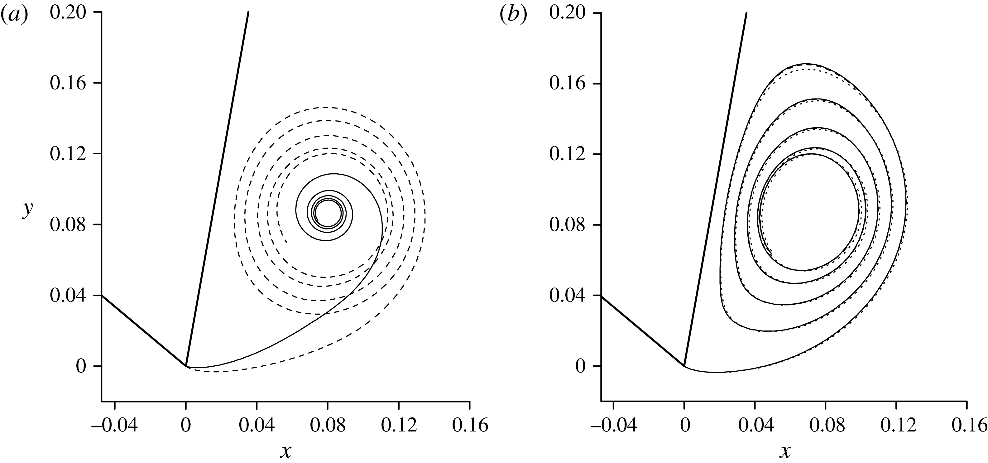
: (a) the initial shape (solid line) and after
 $k=1500$
iterations (dashed line); (b) the same for
 $k=6000$
(dotted line),
 $k=13\,000$
(dashed line) and
 $k=26\,000$
(solid line).
An under relaxation procedure is adopted to achieve the convergence of the iteration process determining the slope of the sheet. At the
 $k+1$
iteration, we have
 $$\begin{eqnarray}\displaystyle \overline{\unicode[STIX]{x1D6FF}}_{vi}^{k+1}=r\unicode[STIX]{x1D6FF}_{vi}^{k+1}+(1-r)\unicode[STIX]{x1D6FF}_{vi}^{k}, & & \displaystyle\end{eqnarray}$$
where the relaxation parameter is chosen in the range from
 $r=0.001\div 0.01$
. Then, the shape of the vortex sheet at the
 $(k+1)$
th iteration is obtained as
 $$\begin{eqnarray}\displaystyle z_{0i}^{k+1}=z_{0i}^{k}+\exp [\text{i}(\overline{\unicode[STIX]{x1D6FF}}_{vi}^{k+1}+\overline{\unicode[STIX]{x1D6FF}}_{vi-1}^{k+1})/2](s_{i}^{k}-s_{i-1}^{k}), & & \displaystyle\end{eqnarray}$$
and the arc length of each segment
 $s_{i}^{k+1}-s_{i-1}^{k+1}$
of the sheet is determined from
 $s_{i}^{k+1}=s_{i-1}^{k+1}+|z_{0i}^{k+1}-z_{0i-1}^{k+1}|$
. At each
 $k$
th iteration of the vortex sheet, the parameters
 $\unicode[STIX]{x1D706}_{i}^{k}$
are determined from (3.4) and (3.5).
3.2 Convergence of the numerical method
The solution of the system of integral equations (2.24) and (2.28) is obtained with the number of nodes
 $N=100$
on the free surface, and
 $M=700$
on the vortex sheet. These two numbers have been found sufficiently large through comparison with the results from
 $N=200$
and
 $M=1400$
. The convergence process of the solution for
 $2\unicode[STIX]{x1D6FC}=60^{\circ }$
and
 $2\unicode[STIX]{x1D6FF}_{h}=20^{\circ }$
is shown in figure 2. Iteration starts from the initial shape given by (3.9) with
 $M_{1}=M/4$
and
 $\unicode[STIX]{x1D6FF}_{vM_{1}}=\unicode[STIX]{x1D6FD}_{R}$
. The inner part of the vortex sheet is chosen to be tight and is expected to expand during the iteration. It can be seen that after 1500 iterations the rings have expanded and the shape of the inner spiral part becomes more elliptical than circular. The shapes at
 $k=13\,000$
and 26 000 almost coincide, as can be seen from figure 2(b). A large number of iterations is required due to the small value of the relaxation parameter
 $r=0.001$
chosen to prevent self-crossing of the vortex sheet, which can lead to the breakdown of the calculation.
The number of coils of the vortex sheet,
 $N_{c}$
, is another parameter of the numerical procedure. It should be chosen large enough to minimize the effect of the approximation of the inner part of the vortex sheet by lumping the vortex at the centre of the spiral. Figure 3 shows the shape of the vortex sheets and pressure distribution on the wedge sides corresponding to
 $N_{c}=4,5$
and 6. The sheet shapes are in good agreement overall. Some difference may be still visible when approaching the centre of the spiral. This is obviously caused by the truncation of the coil number, and larger error is expected at the place where the truncation is made. The difference of the sheet shape near the coil centre does not have a visible effect on the pressure distribution. In fact, the pressure distributions from
 $N_{c}=5$
and 6 are almost the same, as can be seen in figure 3(b). In further computations
 $N_{c}=5$
is chosen, which is satisfactory for the purpose of the study below.
Effect of the number of coils,
 $N_{c}$
, (a) on the shape of the vortex sheet and (b) the pressure distribution for the wedge angle
 $2\unicode[STIX]{x1D6FC}=60^{\circ }$
and the heel angle
 $\unicode[STIX]{x1D6FF}=20^{\circ }$
:
 $N_{c}=6$
,
 $J=0.354$
,
 $\unicode[STIX]{x1D706}_{M}=0.684$
(solid line and solid circle);
 $N_{c}=5$
,
 $J=0.355$
,
 $\unicode[STIX]{x1D706}_{M}=0.654$
(dashed line and opened circle);
 $N_{c}=4$
,
 $J=0.355$
,
 $\unicode[STIX]{x1D706}_{M}=0.592$
(dotted line and solid square.)

The behaviour of the vortex strength, in the form of
 $\unicode[STIX]{x1D6FE}^{\prime }=-\text{d}\unicode[STIX]{x1D706}/\text{d}s$
, and velocity magnitudes on both sides of the sheet are shown in figure 4 as functions of the polar angle
 $\unicode[STIX]{x1D712}$
about the centre of the spiral (point
 $E$
) measured from the
 $x$
-axis. It can be seen that these results exhibit oscillatory behaviour. As may be seen in the figure, at the maxima of the sheet strength the velocity magnitudes on both sides of the sheet take their minimum values, while at the minima of the sheet strength, the velocity magnitudes reach their maximum values. The same behaviour was observed by Pullin (Reference Pullin1978) for flow over a wedge without a free surface. Following Moore (Reference Moore1975), Smith (Reference Smith1968) and Pullin (Reference Pullin1978), wherein details can be found, the oscillatory behaviour of the vortex strength is also related to the shape of the sheet, which exhibits ellipticity that may be defined as the ratio of the largest radius to the smallest one over one complete turn. This may be seen in figure 3 and in other results given below.
Variation of vortex strength along the vortex sheet (solid line) and velocity magnitude on the ‘
 $+$
’ (dashed line) and ‘
 $-$
’ sides of the sheet for the case shown in figure 3.

3.3 Numerical results for asymmetric water entry of the wedges
In the context of figure 1(a), the flow is symmetric with respect to axis of the wedge for
 $\unicode[STIX]{x1D6FE}_{\infty }=90^{\circ }$
and
 $\unicode[STIX]{x1D6FF}_{h}=0$
, and is asymmetric in all other cases. The wedge heel angle may vary in the range bounded by some constraints. For a positive
 $\unicode[STIX]{x1D6FF}_{h}$
, the deadrise angle on the left-hand side,
 $\unicode[STIX]{x03C0}-\unicode[STIX]{x1D6FD}_{L}>0$
, should remain positive, or
 $\unicode[STIX]{x03C0}/2-\unicode[STIX]{x1D6FC}-\unicode[STIX]{x1D6FF}_{h}>0$
. The deadrise angle on the right-hand side of the wedge,
 $\unicode[STIX]{x1D6FD}_{R}$
, should be less than a critical angle
 $\unicode[STIX]{x1D6FD}_{R}^{\ast }$
, beyond which the fully attached solution, i.e. the solution for which the leeward side remains in contact with water, might not exist or might not be physical. Semenov & Yoon (Reference Semenov and Yoon2009) found that the critical angle
 $\unicode[STIX]{x1D6FD}_{R}^{\ast }=\unicode[STIX]{x1D6FE}_{\infty }\pm \unicode[STIX]{x1D6E5}$
, where the value
 $\unicode[STIX]{x1D6E5}$
is of the order of a few degrees, and that its exact value depends on the flow configuration. If we use
 $\unicode[STIX]{x1D6FD}_{R}^{\ast }\approx \unicode[STIX]{x1D6FE}_{\infty }$
then the constraint is
 $\unicode[STIX]{x1D6FC}-\unicode[STIX]{x1D6FF}_{h}>0$
for the case of vertical entry, and the range of the heel angle is approximately
 $0<\unicode[STIX]{x1D6FF}_{h}<\unicode[STIX]{x1D6FC}$
.
Streamline pattern (solid line) and the vortex sheet (dashed line) for the wedge
 $2\unicode[STIX]{x1D6FC}=30^{\circ }$
: (a)
 $\unicode[STIX]{x1D6FF}_{h}=5^{\circ }$
,
 $J=0.064$
,
 $\unicode[STIX]{x1D706}_{M}=0.257$
and (b)
 $\unicode[STIX]{x1D6FF}_{h}=14.2^{\circ }$
,
 $J=0.429$
,
 $\unicode[STIX]{x1D706}_{M}=0.431$
.

The free streamlines and vortex sheet for wedge angle
 $2\unicode[STIX]{x1D6FC}=30^{\circ }$
are shown in figure 5 for the heel angles
 $\unicode[STIX]{x1D6FF}_{h}=5^{\circ }$
and
 $14.2^{\circ }$
. The second case corresponds approximately to the limit heel angle
 $\unicode[STIX]{x1D6FD}_{R}^{\ast }$
. The enlargement near the apex clearly shows the streamline separation from the wedge apex and the spiral vortex sheet. There are also two stagnation points. One is point
 $A$
on the windward side, as shown in figure 1(a), from which the zero streamline splits into two streamlines and one of them moves towards the wedge apex and then separates from the apex, enclosing the recirculation region. The other stagnation point occurs on the leeward side. This is generated by reattachment of the zero streamline the wedge side. The zero streamline and some of the closed streamlines inside the re-circulation region almost coincide with some parts of the vortex sheet line. In fact, the zero streamline leaves the windward side tangentially, which is the same as the vortex sheet. Along the streamline the normal velocity is zero by definition. From (3.4) and (2.50), we can have the velocity normal to the vortex line near the apex and it tends to zero at the apex. This leads to two lines almost coincide near the apex, as shown in figure 5. In fact, figure 5 further shows that these two lines remain close to each other near the leeward surface of the wedge. This suggests that the normal velocity of the vortex sheet has remained small. Near the body surface, the zero streamline reattaches to the wedge surface while the vortex line bends to form a spiral line. For flow without the vortex sheet (Semenov & Wu Reference Semenov and Wu2012), the zero streamline will always stay on the body surface even when it turns at the wedge apex. There are no closed streamlines and the streamlines near the
 $y$
-axis from
 $y=-\infty$
will bend near the wedge apex and then move to
 $y=\infty$
.
The size of the spiral vortex region in figure 5(b) for the heel angle
 $\unicode[STIX]{x1D6FC}=14.2^{\circ }$
is approximately twice as large as that in figure 5(a) for
 $\unicode[STIX]{x1D6FC}=5^{\circ }$
. The distance between the stagnation point on the windward side and the wedge apex is also larger in the latter. This is clearly because the flow will be more asymmetric at large
 $\unicode[STIX]{x1D6FF}_{h}$
. A large cross-flow then leads to a larger circulation. This is reflected in figure 5 by
 $J=0.064$
for case (a) and
 $J=0.429$
for case (b). A common feature for both cases in figure 5 is that the size of the spiral vortex region is much smaller than the wetted length of the leeward side of the wedge. This is because, even though the magnitude of the velocity leaving the windward in (2.50) may be comparable with the entry speed, especially in case (b), it turns very fast and forms a spiral with small radius. As the vortex sheet is far away from the free surface, its effect on the free surface is rather small. In figure 5 the free surface for the flow with a vortex sheet is shown by the solid line, while for the attached flow without a vortex sheet it is shown by the dashed line with symbols. The difference between them is hardly visible, and they virtually coincide.
Pressure coefficient along (a) (
 $s<0$
) and (b) (
 $s>0$
) hand sides of the wedge for the wedge
 $2\unicode[STIX]{x1D6FC}=30^{\circ }$
: (a)
 $\unicode[STIX]{x1D6FF}_{h}=5^{\circ }$
and (b)
 $\unicode[STIX]{x1D6FF}_{h}=14.2^{\circ }$
. The dashed lines correspond to the flow model without a vortex sheet.

In figure 6 the pressure distributions on the wedge corresponding to the flow with and without a vortex sheet are compared for the cases shown in figure 5. It is clearly seen that pressure distributions coincide almost everywhere except for a small region near the apex. Together with the small effect of the vortex sheet on the free surface considered above, the effect of the spiral vortex is very much limited to the local area. However, precisely in the local area near the apex, the presence of the vortex sheet is crucial. It has completely changed the flow pattern, discussed previously. Here the vortex-free solution gives infinite pressure at the apex, or the solution is singular there. The inclusion of the vortex sheet removes this unphysical singularity, and the pressure at the apex becomes finite, as shown in figure 6 for both cases. In the enlargement it can be seen through the fact that, as
 $s$
increases from
 $s=0$
on the leeward side, the pressure drops to its minimal value and then increases. From the analysis of the results it is found that the point of the minimal pressure coefficient on the leeward side is nearest to the centre of the spiral. By comparing figure 6(a,b) it is seen that the larger the heel angle, the larger the drop of the local pressure on the leeward side.
In figure 6(b), the vortex-free solution with a singularity at the apex (dashed line) predicts negative pressure coefficient on the whole leeward side (
 $s>0$
) of the wedge. We should notice that this is in the context that
 $\unicode[STIX]{x1D6FF}_{h}=14.2^{\circ }$
corresponds to the limit discussed above. In contrast to this, the solution with a vortex sheet predicts a local positive maximum near the stagnation point on the leeward side of the wedge, where the zero streamline reattaches to the body surface at a right angle, which can be seen through the enlargement of the streamline patterns in figure 5(b). The pressure on the leeward side is very sensitive to the heel angle near its limit value. Therefore, a slight increase of the heel angle decreases the pressure coefficient rapidly, making the pressure coefficient negative along the whole leeward side of the wedge. In such a case no converged solutions could be obtained. For wedge angles
 $2\unicode[STIX]{x1D6FC}=60^{\circ }$
and
 $90^{\circ }$
the free-surface shape and streamline patterns are shown in figure 7. For the larger wedge and heel angles, the stagnation point on the windward side moves further away from the apex. There is also a larger cross-flow at the wedge apex. This results in a larger size of the separation region with a larger overall circulation on the leeward side. The shape of the closed streamlines inside the separated zero streamline look similar in figure 7(a,b), but the radius is larger for the larger heel angle. The effect of the vortex sheet on the free-surface shape remains small and the difference between the solutions with and without a vortex sheet are virtually invisible. Figure 8 shows the pressure distributions on the wedge for the cases shown in figure 7. For the larger wedge and heel angles, the pressure drops rapidly on the leeward side and reaches its minimum near the centre of the spiral. Away from apex, the pressure distribution virtually coincides with that obtained from the previous solution of the water-entry problem without a vortex sheet (Semenov & Wu Reference Semenov and Wu2012).
Streamline pattern (solid line) and the vortex sheet (dashed line) for the wedge angles:
 $2\unicode[STIX]{x1D6FC}=60^{\circ }$
(a)
 $\unicode[STIX]{x1D6FF}_{h}=10^{\circ }$
,
 $J=0.083$
,
 $\unicode[STIX]{x1D706}_{M}=0.436$
and (b)
 $\unicode[STIX]{x1D6FF}_{h}=27^{\circ }$
,
 $J=0.724$
,
 $\unicode[STIX]{x1D706}_{M}=0.592$
;
 $2\unicode[STIX]{x1D6FC}=90^{\circ }$
(c)
 $\unicode[STIX]{x1D6FF}_{h}=20^{\circ }$
,
 $J=0.169$
,
 $\unicode[STIX]{x1D706}_{M}=0.535$
and (d)
 $\unicode[STIX]{x1D6FF}_{h}=37^{\circ }$
,
 $J=0.801$
,
 $\unicode[STIX]{x1D706}_{M}=0.627$
.

Pressure coefficient along the windward (
 $s<0$
) and leeward (
 $s>0$
) sides of the wedge at
 $2\unicode[STIX]{x1D6FC}=60^{\circ }$
, (a)
 $\unicode[STIX]{x1D6FF}_{h}=10^{\circ }$
and (b)
 $\unicode[STIX]{x1D6FF}_{h}=27^{\circ }$
. The dashed lines correspond to the flow model without vortex sheet.

The values of the pressure coefficient at the apex,
 $c_{pC}$
, minimal pressure on the leeward side of the wedge,
 $c_{p\,min}$
, the total circulation,
 $J$
, and the parameter
 $\unicode[STIX]{x1D706}_{M}$
are shown in table 1 for wedges of different inner angles and heel angles. It can be seen from the table that the pressure coefficient at the wedge apex and the minimal pressure coefficient on the leeward side decrease while the total circulation increases as the heel angle increases.
Some detailed results for vertical water entry of various wedges.

The force on the wedge is evaluated through integration of the pressure distribution along its sides. The drag is defined as the force component along the incoming velocity direction. Its coefficient,
 $C_{d}$
, can be written as:
 $$\begin{eqnarray}\displaystyle C_{D}=C_{R}\sin (\unicode[STIX]{x1D6FE}_{\infty }-\unicode[STIX]{x1D6FD}_{R})+C_{L}\sin (\unicode[STIX]{x1D6FD}_{L}-\unicode[STIX]{x1D6FE}_{\infty }), & & \displaystyle\end{eqnarray}$$
where
 $$\begin{eqnarray}\displaystyle C_{\{R,L\}}=\frac{2}{\unicode[STIX]{x1D70C}V_{y}^{2}H^{2}}\int _{0}^{V_{\{O,B\}}t}P(S)\,\text{d}S=\frac{1}{h}\int _{\{0,c\}}^{\{c,\infty \}}c_{p}[s(\unicode[STIX]{x1D709})]\,\text{d}\unicode[STIX]{x1D709}, & & \displaystyle\end{eqnarray}$$
are the coefficients of the forces normal to the right- and left-hand sides of the wedge, respectively. The
 $y$
-component of the incoming velocity, or
 $V_{y}=V\sin \unicode[STIX]{x1D6FE}_{\infty }$
, has been used as a reference velocity. The moment coefficient,
 $C_{M}$
, about the wedge apex is
 $$\begin{eqnarray}\displaystyle C_{M}=\frac{2}{\unicode[STIX]{x1D70C}V_{y}^{2}H^{2}}\int _{0}^{V_{O}t+V_{B}t}(S_{O}-S)P(S)\,\text{d}S=\frac{1}{h^{2}}\int _{0}^{\infty }[v_{0}-s(\unicode[STIX]{x1D709})]c_{p}[s(\unicode[STIX]{x1D709})]\frac{\text{d}s}{\text{d}\unicode[STIX]{x1D709}}\,\text{d}\unicode[STIX]{x1D709}, & & \displaystyle\end{eqnarray}$$
where
 $$\begin{eqnarray}\displaystyle H=V_{y}th,\quad S_{O}=v_{0}Vt,\quad h=\sin \unicode[STIX]{x1D6FE}_{\infty }[\cot \unicode[STIX]{x1D6FD}_{R}+\cot \unicode[STIX]{x1D6FD}_{L}],\quad c_{p}=\frac{2(P-P_{a})}{\unicode[STIX]{x1D70C}V_{y}^{2}\sin \unicode[STIX]{x1D6FE}_{\infty }}. & & \displaystyle\end{eqnarray}$$
It can be seen from figure 9 that the vortex sheet also has a small effect on the force coefficients. This is of course expected taking into account the fact that the effect of the vortex sheet on the pressure distribution is very much localized.
Drag force coefficient (left axis) and moment about the wedge apex (right axis) versus normalized heel angle
 $\unicode[STIX]{x1D6FF}_{h}/\unicode[STIX]{x1D6FF}_{h}^{\ast }$
, where
 $\unicode[STIX]{x1D6FF}_{h}^{\ast }=14.2^{\circ }$
,
 $27^{\circ }$
and
 $37^{\circ }$
for the wedge angles
 $2\unicode[STIX]{x1D6FC}=30^{\circ }$
,
 $60^{\circ }$
and
 $90^{\circ }$
, respectively. The solid and dashed lines correspond to results with and without vortex sheet respectively.

The free-surface shape and streamline patterns are shown in figure 10 for the case of oblique entry at
 $2\unicode[STIX]{x1D6FC}=90^{\circ }$
and
 $2\unicode[STIX]{x1D6FC}=120^{\circ }$
. The wedges are symmetric about the
 $y$
-axis. The stagnation point on the windward side can be clearly seen, and it moves further away from the apex for the larger oblique angles. The cross-flow over the apex creates a separation region similar to that observed for vertical entry of the heeled wedge. For the wedge of angle
 $2\unicode[STIX]{x1D6FC}=90^{\circ }$
the inflow velocity angle
 $\unicode[STIX]{x1D6FE}=45^{\circ }$
is close to the limit oblique angle for which the attached solution might be found. For larger oblique angle, or larger horizontal component of the velocity, the separation region becomes larger. However, its size remains relatively small in comparison with the wetted length of the wedge. Similar results are shown for the wedge angle
 $2\unicode[STIX]{x1D6FC}=120^{\circ }$
and the inflow velocity angles
 $\unicode[STIX]{x1D6FE}=70^{\circ }$
and
 $30^{\circ }$
. The latter is close to the limit oblique angle. At a given wedge angle the size of the separation region increases as the horizontal component of the inflow velocity increases, and it becomes largest at the limit oblique angle
 $\unicode[STIX]{x1D6FE}_{\infty }$
. The size is of course also affected by the wedge angle itself. If we compare these two limiting cases in figure 10 (cases (b) and (d)), it can be seen that the size of separation region for the wedge of angle
 $2\unicode[STIX]{x1D6FC}=90^{\circ }$
at
 $\unicode[STIX]{x1D6FE}=45^{\circ }$
is approximately twice that for
 $2\unicode[STIX]{x1D6FC}=120^{\circ }$
at
 $\unicode[STIX]{x1D6FE}=30^{\circ }$
. This is partly because the effort for the flow to turn around the apex decreases when the wedge angle
 $2\unicode[STIX]{x1D6FC}\rightarrow 180^{\circ }$
, and is also related to
 $\unicode[STIX]{x1D6FE}_{\infty }$
. The pressure distributions corresponding to the cases in figure 10 are shown in figure 11. In all of the cases the effect of the vortex sheet is localized near the apex, and away from the apex the pressure almost coincides with that corresponding to the attached flow.
The pressure coefficient at the apex and the minimal pressure coefficient on the leeward side as well as the total circulation are shown in table 2.
Streamline pattern (solid line) and the vortex sheet (dashed line) for the oblique water entry of the wedge:
 $2\unicode[STIX]{x1D6FC}=90^{\circ }$
(a)
 $\unicode[STIX]{x1D6FE}_{\infty }=60^{\circ }$
,
 $J=0.737$
,
 $\unicode[STIX]{x1D706}_{M}=0.477$
and (b)
 $\unicode[STIX]{x1D6FE}_{\infty }=45^{\circ }$
,
 $J=1.245$
,
 $\unicode[STIX]{x1D706}_{M}=0.600$
;
 $2\unicode[STIX]{x1D6FC}=120^{\circ }$
(c)
 $\unicode[STIX]{x1D6FE}_{\infty }=70^{\circ }$
,
 $J=0.444$
,
 $\unicode[STIX]{x1D706}_{M}=0.629$
and (d)
 $\unicode[STIX]{x1D6FE}_{\infty }=30^{\circ }$
,
 $J=1.303$
,
 $\unicode[STIX]{x1D706}_{M}=0.512$
.

Pressure distribution along the windward (
 $s<0$
) and leeward (
 $s>0$
) sides of the wedge for oblique entry at
 $2\unicode[STIX]{x1D6FC}=90^{\circ }$
, (a)
 $\unicode[STIX]{x1D6FE}_{\infty }=60^{\circ }$
and (b)
 $\unicode[STIX]{x1D6FE}_{\infty }=45^{\circ }$
, and
 $2\unicode[STIX]{x1D6FC}=120^{\circ }$
, (c)
 $\unicode[STIX]{x1D6FE}_{\infty }=70^{\circ }$
and (d)
 $\unicode[STIX]{x1D6FE}_{\infty }=30^{\circ }$
. The dashed lines correspond to the flow model without vortex sheet.
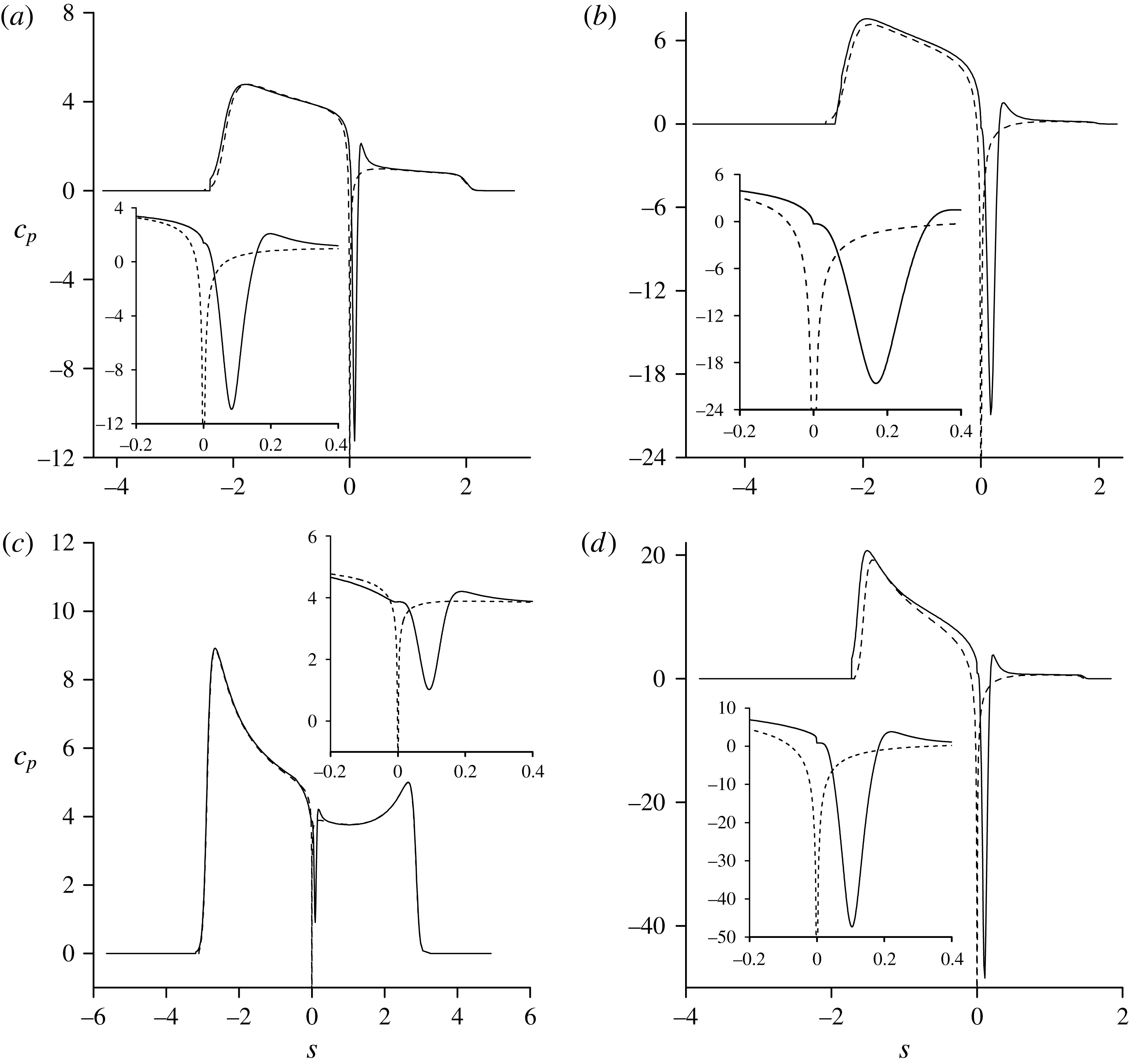
Some detailed results for oblique water entry of various wedges.

4 Conclusions
The problem of asymmetric flow due to water entry of a wedge with the rolled-up vortex sheet shed from the apex is considered. The integral hodograph method has been employed to determine in an explicit form the complex potential and the flow singularities corresponding to vortex-free flow. This provides an incoming flow for the vortex sheet shed from the wedge apex, whose solution is obtained from the Birkhoff–Rott integral equation which determines the vortex sheet dynamics. Numerical results are obtained for wedges of a range of inner, heel and oblique angles.
The obtained flow patterns show the formation of the recirculation/separation region with a stagnation point on the leeward side of the wedge due to the reattachment of the streamline shed from the apex to the body surface. The size of the separation region is estimated based on the area bounded by the zero streamline linking the wedge apex and the stagnation point on the leeward side. The region inside this streamline increases when the overall flow is more asymmetric and the velocity at the apex on the windward side becomes larger. However, the size of the separation region is relatively small, compared with the wetted length of the leeward side of the wedge. Thus, the vortex sheet has a small effect on the free surface and its principal effects are on the velocity and the pressure near the apex, as well as the flow configuration inside the flow separation region. The vortex sheet removes the singularity in the attached flow solution, leading to a finite pressure and velocity at the apex. The location of the minimal pressure is found to be on the leeward side of the wedge near the apex, and is near the point with minimal distance to the centre of the spiral sheet.
The vortex sheet shed from the apex exhibits a shape more elliptical than circular, which is similar to that found by Pullin (Reference Pullin1978) for flow past a wedge in an unbounded fluid domain without a free surface. The vortex strength along the spiral sheet undergoes an oscillatory process together with the velocity magnitudes on the both sides of the sheet, and the magnitudes of their oscillations decay toward the centre of the spiral.
Acknowledgements
This work is supported by Lloyd’s Register Foundation (LRF) through the joint centre involving University College London, Shanghai Jiaotong University and Harbin Engineering University, to which the authors are most grateful. LRF supports the advancement of engineering-related education, and funds research and development that enhances safety of life at sea, on land and in the air.



