Nomenclature
- CORSIA
-
Carbon Offsetting and Reduction Scheme for International Aviation
- CO2
-
carbon dioxide
- EU
-
European Union
- F
-
thrust [N]
- HEX
-
heat exchanger
- IATA
-
International Air Transport Association
- ICAO
-
International Civil Aviation Organization
- ISA
-
International Standard Atmosphere
- MCL
-
maximum climb (top of climb)
- MCR
-
maximum cruise
- MTO
-
maximum take-off
- MTOW
-
maximum take-off weight, kg
- NOx
-
nitrogen oxides
- NPSS
-
numerical propulsion system simulation
- P
-
power, W
- PR
-
pressure ratio
- Q
-
heat, W
- TAKO
-
take-off
- TMS
-
thermal management system
- V
-
velocity, m/s
- W
-
weight, kg
Symbols
-
 $\dot C$
-
capacity flow,
$kg/s$
-
${\rm{\Delta }}$
-
Delta
-
$\varepsilon $
-
heat exchanger effectiveness
- η
-
efficiency
- m
-
mass, kg
-
$\dot Q$
-
heat flow,
$W$
-
$T$
-
total temperature,
$K$


Subscripts
-
$cold$
-
cold side
- d
-
drag, N
- g
-
gross
-
$hot$
-
hot side
- in
-
entry
- min
-
minimum
- out
-
out
-
$ref$
-
reference
-
$rel$
-
relative
- TMS
-
thermal management system


1.0 Introduction
By emitting greenhouse gases, particularly carbon dioxide, nitrogen oxides and water vapour, the commercial aviation industry contributes to climate change. The global contribution of aviation to anthropogenic global warming is 3.5%. However, only one-third of aviation’s climate impact can be linked to CO2 emissions, while two-thirds are due to non-CO2 factors. In particular, condensation trails and the resulting condensation cirrus clouds have the most significant impact [Reference Lee, Fahey and Skowron1] . The Paris Climate Agreement was established to set political and societal climate goals to significantly reduce the effects of anthropogenic climate change [2]. In order to develop strategies and proposals to achieve these climate goals, numerous international and European organisations are working together with industry, research and politics. For example, the International Civil Aviation Organization (ICAO) is launching Carbon Offsetting and Reduction Scheme for International Aviation (CORSIA), a carbon offsetting and reduction programme for international aviation [3]. International Air Transport Association (IATA) also offers its Fly Zero Net Roadmaps, which provide step-by-step guidance on how to meet the Paris climate targets [4, 5]. The European Commission launched the European Green Deal, which aims to achieve zero net greenhouse gas emissions by 2050 [6]. The Fit for 55 legislative package has been developed as a first step towards the goal of reducing greenhouse gas emissions in the EU by at least 55% by 2030 compared to 1990 levels [7]. To achieve this objective, new disruptive propulsion concepts are being investigated. The focus is particularly on propulsion systems with a modified thermodynamic cycle, hybrid electric propulsion systems or systems powered by a fuel cell. In hybrid electric and fuel cell systems, sensitive components like batteries, electric motors and fuel cells need to operate within specific temperature ranges to maintain the required performance. Without efficient heat dissipation, components can overheat, leading to reduced efficiency and potential failure. In this paper, disruptive engines are hybrid electric propulsion system concepts. For the implementation of such concepts, a complex thermal management system is indispensable. The objective is to ensure that the thermal management system (TMS) provides the necessary cooling capacity, but impair the overall system efficiency as little as possible.
Heat exchangers, which are the core component of any TMS, are commonly sized for the highest required heat dissipation. This is usually the take-off operating point for subsonic applications. In cruise flight, where the ambient temperature is significantly lower and hence the temperature difference for the heat exchanger significantly higher, the problem arises that the heat exchanger might now be oversized. The challenge is to find a TMS design and control system that allows an operation that leads to minimal mission energy consumption on the propulsion system level, including TMS for the selected reference mission without risking freezing of the coolant. Current solutions for heat dissipation typically rely on a heat exchanger in a ram air duct, as described in Refs [Reference Kellermann8–Reference Coutinho, Bento and Souza10]. However, these designs go along with an inherently significant nacelle drag and mass because the heat exchanger is designed for extreme operating points, such as battery charging or take-off on a hot day. The publication in Ref. [Reference Kellermann8] describes a thermal system for cooling electric drives and utilises a fan located behind the heat exchanger for especially hot days. The integration of the cooling system results in relatively large nacelles due to the associated drag. This oversized system provides necessary cooling capacity during take-off but causes unnecessary weight and drag during cruise flight. Additionally, extremely cold days, which pose a particular challenge for battery-powered aircraft, are not taken into consideration. Other solutions, such as Ref. [Reference Schiltgen and Freeman9], use distributed propulsion systems with an integrated thermal system located only on the outer edge of the wing, which operate exclusively through ram air. However, these solutions have the disadvantage of a large and heavy thermal system, particularly a large nacelle housing the heat exchanger, causing high drag in cruise flight. This directly increases the power demand of the system. A third work shown in Ref. [Reference Coutinho, Bento and Souza10] presents an overview of thermal management systems that have been examined in the literature and in projects.
The following investigations are based on a TMS which is installed in nacelles. An alternative would be to position the TMS in the fuselage of the aircraft. It is assumed that the integration into the aircraft would not lead to significant benefits since the mass of the heat exchangers would not be considerably less (the same amount of waste heat has to be dissipated). Additionally, the TMS installed in the nacelles potentially does not increase the installation drag compared to a TMS installed in the fuselage.
Designing solely for an individual operating point might lead to an isolated perspective not taking into account snowball effects that significantly influence the overall performance of the TMS. For example, if the TMS is designed for take-off, it might cause high spillage drag during cruise. Only if both operating conditions are taken into consideration in the design of the TMS will this lead to an acceptable overall thermal management system with the ability to dissipate enough heat during taxiing and take-off, but also with acceptable nacelle drag during cruise.
Additionally, studies in the literature show approaches to design an explicit system for a clearly defined application. However, such general approaches could help to find the optimal configuration within conceptual design studies, but also to understand the potentials, challenges and first-order impacts of different thermal management configurations.
1.1 Objective
This research aims to develop a versatile model of a ram-air-based thermal system suitable for disruptive propulsion concepts, accompanied by essential design guidelines for assessment. The model’s adaptability to represent diverse aircraft is considered, accounting for the effect on the aircraft through a simplified representative model. Emphasis is placed on addressing the challenge of dissipating a high heat load, particularly at low flight Mach numbers. Not integrating a fan into the TMS could result in sub-optimal designs in terms of weight, aerodynamic performance and airframe installation. The investigation includes determining the number of installed electric fans to build an efficient cooling system. A comparative analysis is conducted using two mission profiles for short and medium range.
The study explores the potential impact and utilisation of the Meredith effect, considering TMS mass and installation drag at the same time. The Meredith effect refers to a phenomenon wherein the aerodynamic drag induced by a cooling radiator can be compensated through the heat, which is added by the installed heat exchanger resulting in thrust [Reference Meredith11]. A variable nozzle is designed, modeled and evaluated in terms of mission energy for the reference missions. Various heat exchanger types are assessed for overall mission energy, installation drag, internal pressure loss and mass. This paper provides design guidelines for sizing fans, electric motors, nozzles and nacelles for thermal management systems. Different TMS configurations are scrutinised for opposing effects, including altitude influence and interactions among installed fans and flow guides. Additionally, the impact on the overall system due to varying inlet velocities and temperatures in the heat exchanger matrix, diffuser and system inlet is analysed.
The research aims to identify optimal design ranges for diverse applications and configurations, such as hybrid electric systems, outlining the advantages and disadvantages of each. Quantitative results pertaining to overall power demand, masses and drag are compared among configurations, with a focus on influences and interactions. An exemplary propulsion system, representing a hybrid electric propulsion type serves as the basis for evaluation.
2.0 Configurations
In this paper, four different TMS configurations are evaluated in relation to the total energy requirement of the overall system. The four configurations of the thermal management system are now explained in detail.
2.1 Configuration 1: reference – ram air
The reference thermal management system, irrespective of its installation, features an air inlet for essential mass flow, converting incoming fluid kinetic energy to augment static pressure and minimise losses. A diffuser in the system enlarges the channel cross-section, reducing flow velocity and increasing static pressure, guided by the area ratio. The pressure coefficient of the diffuser is influenced by static pressure and dynamic pressure. Ensuring a half-opening angle between 7 and 14 degrees in diffuser design, as investigated by Refs [Reference Idelcik12, Reference Bräunling13], mitigates separation phenomena near the wall, sustaining efficient pressure increase without compromising system stability. After the diffuser, the air enters the heat exchanger with the air mass flow and air temperature depending on the operating condition, experiencing a heat transfer from the hotter cooling fluid flow with a prescribed inlet temperature and a cooling fluid mass flow that results in the desired exit cooling flow temperature. The cooling fluid mass flow is controlled so that the inlet temperature of the heat exchanger is kept constant. The cold air flow undergoes a temperature rise due to the absorbed heat output. Furthermore, the heated air is expanded to ambient pressure through a variable nozzle. The reference TMS is shown in Fig. 1.
Ram air-based configuration, which is used as the reference TMS.

2.2 Configuration 2: upstream fan
In the configuration shown in Fig. 2, a fan stage is positioned before the heat exchanger, allowing for reduced flow velocity and influencing entry conditions and pressure losses. This configuration will be called “pushing fan”. The fan is driven by an electric motor to increase the mass flow. Due to the increased pressure and reduced velocity resulting from the fan installed in the TMS, the diffuser in front of the HEX can be made shorter in this configuration. The shortened diffuser is a benefit, but the energy input raises air temperature, diminishing the entry temperature gradient of the heat exchanger. Consequently, higher air mass flow is required for the required heat dissipation. This variant requires higher mass flows and compressor power compared to the prior configuration, where no compressor is installed, resulting in increased heat dissipation by the TMS at constant propulsion power. The larger system, increased TMS mass, and higher aerodynamic drag contribute to an overall higher propulsion power.
Configuration with an upstream fan, here called pusher fan.

2.3 Configuration 3: downstream fan
The configuration in Fig. 3 introduces a fan stage behind the heat exchanger, here called “pulling fan”. The compressor compensates pressure losses caused by the heat exchanger and enables mass flow adjustments, allowing for higher mass flows at lower flight velocities and anticipating a more compact TMS. Similar to the fanless variant, there is no temperature rise caused by the compressor before entering the heat exchanger, resulting in lower air inlet temperatures and maintaining a significant temperature gradient to the hot fluid side. Significant temperature differences between the fluids reduce mass flow requirements. However, the upstream diffuser must be designed for minimal pressure loss. This requires an extended diffuser with low pressure loss for efficient entry into the heat exchanger. Since there is no fan installed between diffuser and HEX, which reduces the velocity, the diffuser is longer than the upstream fan configuration. Crucially, the fan stage is electrically driven and contributes directly to the overall power requirements of the aircraft. This increases the heat dissipation requirements at constant propulsion power, potentially requiring an increase in overall TMS size.
Configuration with a downstream fan, here called pulling fan.

2.4 Configuration 4: dual fan
Figure 4 examines a TMS configuration with two compressors. This design includes a front fan to condition the heat exchanger and a rear fan to compensate for pressure drop. The goal is to combine the benefits of the previous configurations while mitigating the negative effects. The first fan reduces the inlet velocity, minimises pressure losses and builds up pressure. However, controlling the temperature rise is critical to maintain a significant temperature gradient. The results of mission and performance calculations will determine whether this configuration, with its increased complexity, has any drawbacks, including the potential effects of its length and the increased control effort required to coordinate the two compressors.
Configuration with a down- and upstream fan, here called dual fan.

3.0 Methodology
This chapter discusses the methods and techniques for designing and evaluating a thermal management system at the overall system level. A novel approach is introduced that utilises a fictitious design point. The computational calculation of the components has been optimised for reduced computation time without altering the underlying physics. To illustrate this new methodology, an example is provided:
In a thermal management system including a fan, the required power of the electrical components is not clearly defined at the beginning of the calculation. This is because losses, such as drag, not defined geometry of electrical components, and pressure losses, have not yet been determined. In this example, the fan is sized as a turbomachine within the maximum climb phase (MCL), while the remaining system components of this exemplary TMS are sized at maximum take-off (MTO) conditions. As a result, multiple physically relevant design points exist for different components, which can be considered as independent entities within the overall propulsion system, such as the electric motor or the heat exchanger.
In the classical multi-design point approach, this imbalance would be resolved iteratively. In each iteration, the computational design point would be adjusted based on boundary conditions derived from the physically defining off-design points of the other components. This iterative process leads to high computational effort due to the large number of iterations required.
The new approach introduces a fictitious design point for the solver. This point does not exist in the physical world and serves solely to accelerate the solution process by allowing early specification of design parameters, thereby reducing the number of iterations needed in this example.
3.1 Multidisciplinary design technique
In order to evaluate a TMS in its entirety, it is not always possible to estimate which operating point has to be chosen as the design point. During the MCL, which is the top of climb, the maximum corrected mass flows are reached, which define the fan cross sections. The ram air configuration has its maximum corrected mass flow during take-off. The maximum heat load may occur at different operating points. The electrical components are sized at the point of maximum power demand. Therefore, a multi-design point approach is applied. Crucial performance variables, for example the nozzle pressure ratio or the maximum corrected mass flow, in the fictitious design point are automatically set accordingly. This ensures that all dimensioning operating points are considered, allowing the integration of any component into any propulsion system model independent of its design point. A loop over all operating conditions is used to determine the maximum heat to be dissipated based on the maximum power required and transferred to the fictitious design point. Together with the component geometry, the TMS is then designed, and all other operating points and disciplines are calculated again.
The investigations are performed using the numerical propulsion simulation software (NPSS), which allows the implementation of the design logic presented here, however, this logic can be applied to any performance tool [14].
3.2 Designing thermal management systems with installed fans
An initial study analyses the effectiveness
 $\varepsilon $
, which is defined according to Equation (1) and the relative pressure losses in the heat exchanger for different heat exchanger types. It is essential to distinguish effectiveness from efficiency, as effectiveness relates solely to the transferred heat flux
 $\dot Q$
to the maximum possible heat flux, excluding additional losses such as fluid pressure losses, which can impact the quality of a heat exchanger. Therefore, the optimum design for a heat exchanger is one that minimises pressure losses while maximising efficiency. The use of the smaller capacitance flow
 ${\dot C_{min}}$
follows from the first law of thermodynamics, since two unequal capacities on the hot and cold sides imply that only the smaller capacitance flow can reach the inlet temperature of the other fluid. To calculate the heat transfer, the epsilon-NTU method is applied using NPSS. Within NPSS a plate offset strip fin heat exchanger can be designed with the correlations described in Refs [Reference Shah15–Reference Schlünder18].
 \begin{equation}\varepsilon = \frac{{\dot Q}}{{{{\dot C}_{min}}\left( {{T_{hot,in}} - {T_{cold,in}}} \right)}}\end{equation}
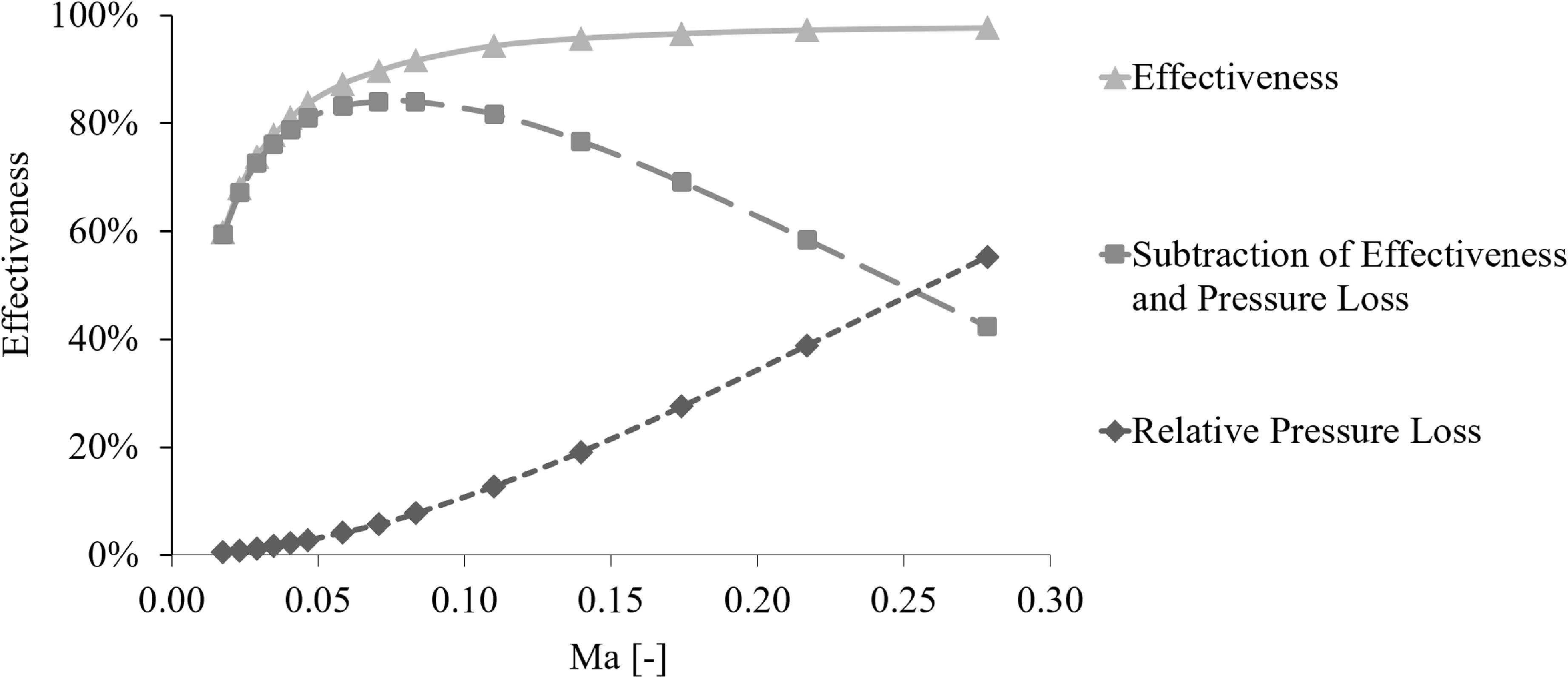
The brief study uses a generic plate heat exchanger with a constant geometry as an example to show that the pressure losses within the heat exchanger rise as the inlet Mach number in the heat exchanger matrix increases. At higher Mach numbers, the flow is more likely to transition from laminar to turbulent. Turbulent flow typically has higher skin friction and viscous effects, contributing to increased pressure losses along the pipes. Therefore, low inlet Mach numbers are set to determine the length of the cooling fluid flow within the heat exchanger.
3.2.1 TMS design
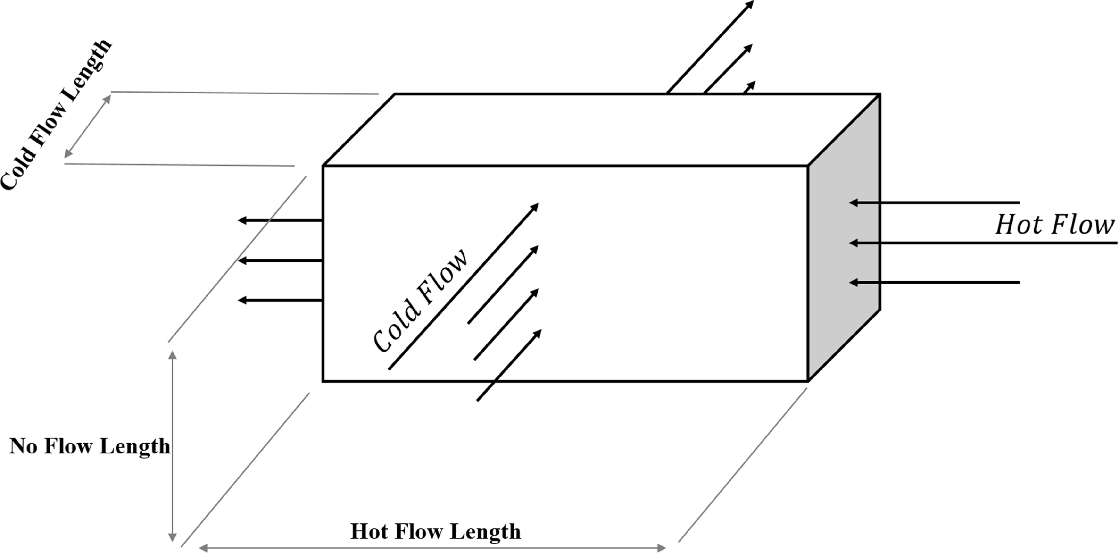
To size the heat exchanger the maximum transferred heat needs to be prescribed. The heat exchanger entry air mass flow is set accordingly. It is assumed that a reasonably low maximum cooling fluid exit temperature also is prescribed, allowing to generate a desired temperature delta to cool the propulsion system components. The air mass flow is defined as the cold flow and the cooling fluid is defined as the hot flow. Here the heat exchanger is assumed as a plate heat exchanger and simplified as a cuboid, see Fig. 5. The no-flow length is defined as the length perpendicular to the hot and cold flow. It is assumed that the ratio of hot-flow length and no-flow length is given, since the modeled heat exchanger is a given industry product and was scaled. The inlet area of the heat exchanger air side is a result of the selected optimal inlet Mach number according to Fig. 6 and the heat exchanger entry conditions. In this study, it was found that the optimal Mach number for this example is around 0.065 regarding effectiveness and pressure loss not taking masses into account. The inlet area of the heat exchanger cooling fluid side is a result of the necessary airflow to transfer the desired heat and the entry conditions (temperature and pressure) of the cooling fluid. The diffuser, which is in front of the heat exchanger, needs to be sized so that the desired heat exchanger entry Mach number is ensured. The cone angle for the diffuser is limited to 12 degrees to avoid excessive pressure losses [Reference Idelcik12, Reference Bräunling13]. The diffuser is designed with the methods described in Ref. [Reference Idelcik12]. Given the cone angle and the diffuser entry conditions the diffuser length is a result. The configurations shown in section 2.0 have one or two fans installed. The task of the fan is to provide enough mass flow at operating points with low flight velocities to ensure enough cooling. The fan pressure ratio is sized to provide a nozzle pressure ratio not lower than 1 plus a safety margin. The relative rotational fan speed is determined with methods described in Ref. [Reference Grieb19]. It is important to notice that the fan pressure ratio and the nozzle pressure ratio are adapted to the specific conditions of the flight envelope by the electric motor. A low fan power is aimed for to minimise size and mass of the fan and electric motor and also overall mission energy. With the help of an electric motor, the fan operating point can be chosen independently within its operational range. Too low fan pressure ratios are prevented by closing the variable nozzle. It is assumed that the electric motor is able to deliver the required power at any operating point.
Sketch of a plate heat exchanger.

Effectiveness and relative pressure loss as a function of the heat exchanger inlet Mach number on an exemplary, generic plate heat exchanger with constant geometry. The subtraction of effectiveness and pressure loss is done by subtracting the effectiveness by the relative pressure loss.

3.2.2 Calculation technique
For the design of a TMS with installed fan(s) on an aircraft level, the following design rules are explained in this work in the form of a system of equations with independent and dependent variables. A distinction is made among universal, design and off-design iterations. The universal iteration is defined as an iteration where the input parameter in one operating point is adjusted to the condition in another operating point. A design point is the operating point in which the individual component, e.g. turbomachinery, electric motor, heat exchanger, is sized. In an off-design point, the geometry of the component or entire system is already set and will generally not be changed. In a universal iteration, the maximum heat demand from an operating point is selected for the design process of the heat exchanger. Moreover, the universal iteration is used to adapt the required aircraft thrust and the delivered propulsion system thrust at the same time. The heat exchanger is designed based on the maximum heat to be transferred. In addition, the mass flow of the cooling medium is determined by the maximum output temperature of the cooling flow. The inlet temperature of the cooling medium into the heat exchanger is the temperature of the fluid after it has passed through the components to be cooled. The aim is to ensure that the outlet temperature of the coolant corresponds to the defined target value of the maximum output temperature of the cooling flow. The integrated fan stage needs to operate on its operating line; therefore, the nozzle throat area is adjusted. The fan assures that the nozzle pressure ratio greater one is achieved. In the overall design, there is a balance of power and shaft speed between the electric motor and the fan stage, which are connected via a shaft. The system has now been determined and the design is defined.
The efficiency of the overall system is an input parameter in this study for evaluating the influence of the heat dissipation rate on the overall system. The efficiency is defined as the ratio between the sum of the TMS and propulsion power (
 ${P_{TMS}} + {P_{Propulsion}})\;$
and the sum of the power plus the power loss, which is expressed as heat
 ${Q_{TMS}}$
, see Equation (2).
 \begin{equation}{\eta _{overall,\;propulsion}} = \;\frac{{{P_{TMS}} + {P_{Propulsion}}}}{{{P_{TMS}} + {P_{Propulsion}} + {Q_{TMS}}}}\end{equation}
3.2.3 Anti-freeze mechanisms
One fundamental problem with the TMS featuring liquid cooling at high altitudes is the risk of freezing, due to the significantly higher delta temperature across the heat exchanger compared to sea level conditions. To prevent coolant freezing, a novel design approach is proposed. This approach involves installing identical TMS modules in separate nacelles. In the event of a freezing risk, individual TMS modules can be closed and shut off, resulting in a higher cooling fluid temperature in the remaining active modules since the cooling fluid runs through all modules. The following section describes the simulation of this system.
If the cooling medium temperature drops below its freezing point plus a safety margin of 10 Kelvin during the mission, the nozzle can be closed within the fan stage’s allowable operational range to maintain operational stability. Therefore, it is assumed that the fan can operate until a minimum pressure ratio of 1 plus a safety margin, and the nozzle can also operate to a pressure ratio of 1 plus a safety margin. These conditions ensure a secure operation controlled by a variable nozzle geometry.
In the following, a TMS with six nacelles is designed, reducing system size and the absolute mass flow per nacelle. The geometry of the nacelles will be set in the design point where the heat exchanger is sized to the maximum heat per nacelle, which needs to be dissipated. The maximum heat per nacelle is identical for each nacelle. The design procedure is the same as described in section 3.2.1. At operating points where the cooling medium would freeze, individual TMS modules can be shut off. The inlet and nozzle are completely closed by a closing mechanism, allowing the electric motor and fan stage to be switched off. This procedure also allows, for instance, to create a constant temperature condition for batteries during cruise flight. Distributing the TMS in different nacelles and providing sophisticated control of the flaps offers the following advantages: the nacelles can be aerodynamically optimised to reduce drag and increase overall system efficiency. Both the diffusers and heat exchangers are designed for greater effectiveness. The system is highly redundant, improving reliability. This allows for the design of different TMS systems for different operating points, enhancing operational capability. The cooling components are decentralised. The system can operate in both hot and cold conditions and at any operating point, including charging, allowing for fully self-sufficient operation. Preconditioning by ground-based systems is not required. A disadvantage of distributed TMS modules is the complex control of the system as well as possible aerodynamic influences along the wing. Figure 7 shows an example of a generic, distributed thermal management system installed on a wing.
Illustrative draft of a generic, distributed TMS exemplary installed on a wing.

3.3 System scaling
In considering the effects of the TMS at the aircraft level, it becomes imperative for the aircraft system to compensate for the drag of the TMS and to dynamically adjust to the corresponding alterations in thrust requirements. This adaptive response ensures the continual successful execution of the required transportation task, even in the presence of elevated thrust demands. Within the scope of this investigation, a ‘re-engineered aircraft’ is defined by a constant wing loading and thrust-to-weight ratio while changing the propulsion system. So the aircraft mission task (range, payload, etc.) remains unchanged. As the system weight escalates, the aircraft’s thrust requirement increases, allowing for the exploration and analysis of consequential snowball effects. The determination of the accurate thrust requirement incorporates the influence of the thermal management system’s thrust. This net thrust is calculated as the difference between the gross thrust and the combined dynamic pressure (ram) drag and nacelle drag at the given operational point. The nacelle drag encompasses friction drag, profile pressure drag, and potential spillage drag.
 \begin{equation}{F_{net,TMS}} = {F_g} - \;{F_{ram}} - {F_d}\end{equation}
The net thrust of the aircraft is defined as the sum of the propulsion and TMS net thrust.
 \begin{equation}{F_{net,\;\;aircraft}} = {F_{net,TMS}} + {F_{net,Propulsion}}\;\end{equation}
If the net thrust of the thermal system is negative, because the thrust generated by the Meredith effect cannot compensate for the drag, then the propulsion system gets heavier, the thrust requirement increases, and the heat to be dissipated also increases. Conversely, if the TMS can generate a positive net thrust, the propulsion will become lighter, and the heat dissipation required will decrease.
The main propulsion system, which is marked with the subscript ‘propulsion’, does not include the TMS, but consists of the main propulsion system only. The thrust-to-weight ratios for the aircraft
 ${\frac{{Thrust}}{{Weight}}_{aircraft}}\;$
and the main propulsion system
 ${\frac{{Weight}}{{Thrust}}_{propulsion}}\;$
are assumed to remain constant. The mass of the TMS is calculated separately. The additional main propulsion weight
 ${\rm{\Delta }}{W_{propulsion}}$
is calculated and thus the influence of the aircraft on the TMS.
 ${\rm{\Delta }}{W_{propulsion}}$
represents the difference in the main propulsion weight due to a different thrust demand. Here, it is assumed that the required thrust can be determined by a constant thrust-to-weight ratio at aircraft level.
 \begin{equation}{F_{aircraft}} = MTO{W_{aircraft}}*{\frac{{Thrust}}{{Weight}}_{aircraft}}\;\end{equation}
The propulsion mass without a thermal system can be defined using a different thrust-to-weight ratio at propulsion level, depending on the type of propulsion (e.g., hybrid electric, turbofan, etc.). The thrust is multiplied by the inverse thrust-to-weight ratio to calculate the propulsion mass
 ${W_{propulsion}}$
, Equation (6).
 \begin{equation}{W_{turbofan}} = MTO{W_{aircraft}}*{\frac{{Thrust}}{{Weight}}_{aircraft}}*{\frac{{Weight}}{{Thrust}}_{propulsion}}\;\end{equation}
If a turboprop propulsion system is used, Equation (7) can be utilised.
 \begin{equation}{W_{turboprop}} = MTO{W_{aircraft}}{\rm{*}}{\frac{{Power}}{{Weight}}_{aircraft}}{\rm{*}}{\frac{{Weight}}{{Power}}_{propulsion}}{\rm{\;}}\end{equation}
The following equation can be iteratively solved to obtain the mass deltas and the additional thrust requirement, since the mass of the TMS is changed by higher system power demands. Possible increases in structural mass are neglected.
 \begin{equation}MTO{W_{new,aircraft}} = MTO{W_{aircraft}} + {W_{TMS}} + {\rm{\Delta }}{W_{propulsion}}\end{equation}
 \begin{align}{\rm{\Delta }}{W_{propulsion}} &= \left( {MTO{W_{aircraft,new}}*{{\frac{{Thrust}}{{Weight}}}_{aircraft}}*{{\frac{{Weight}}{{Thrust}}}_{propulsion}}\;} \right) \nonumber \\[5pt]& \quad- \;\left( {MTO{W_{aircraft}}*{{\frac{{Thrust}}{{Weight}}}_{aircraft}}*{{\frac{{Weight}}{{Thrust}}}_{propulsion}}\;\;} \right)\end{align}
The total mass of the TMS
 ${W_{TMS}}$
is considered within the design process and includes the mass of the heat exchanger, ducts, nacelle, fan stage and electric motor.
3.4 Methods to assess the thermal management system
For the comprehensive system evaluation, masses, drag and power requirements are assessed. The focus here is not on energy consumption but solely on power at each operating point, given that energy equals power multiplied by time. It is assumed that time is a constant for each mission and can be chosen individually. The power requirement pertains to the entire system and can be determined according to section 3.3. The masses of the turbo components are parametrically estimated from the resulting geometry derived from the thermodynamic parameters (Mach number, mass flow) of the cycle process. The weight of electric motors is estimated by a specific torque to weight ratio derived from [Reference Anton and Siemens20]. The size and volume of the fins and the plates separating the mass flows defines the overall mass of the plate heat exchanger with offset stripped fins, see Equation (10) [Reference Shah15].
 \begin{equation}{m_{{\rm{total}}}} = {m_{{\rm{Fins}},hot}} + {m_{{\rm{Fins}},{\rm{cold}}}} + {m_{{\rm{Plates}}}} + {m_{{\rm{Walls}},{\rm{hot}}}} + {m_{{\rm{Walls}},{\rm{cold}}}}\end{equation}
The nacelle’s geometry is determined using inlet areas, length and diameter of individual components, and nozzle areas. Care is taken to ensure that the angle of the afterbody does not exceed 20 degrees to avoid flow separation. Additionally, the nose radius of the inlet lip is dimensioned to minimise spillage drag. The nacelle drag is determined based on its geometry, with profile, frictional and spillage drag calculated according to ESDU 80124. ESDU 81024 provides a method for estimating the drag of axisymmetric cowls at subsonic speeds. The drag is categorised into profile, spillage and wave drag, with the method relying on correlations of experimental data [21]. The correlations are built on critical mass flows, lip radius, Reynolds number and Mach number. Therefore, only rotationally symmetrical nacelles are designed.
The weight of the fan and ducts are derived from the NASA methodology for estimating length and weight of axial flow components. The weights for compressors are estimated with the correlation variables: mean diameter, number of stages, length to inlet mean diameter ratio [Reference Sagerser, Lieblein and Krebs22]. It is assumed that the installed nozzles and diffusers can be handled analog to ducts regarding the weight estimation.
4.0 Study Framework
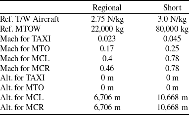
Two different missions, each with an individual aircraft application, are considered for this study. One mission is used for a regional aircraft and a short-haul narrow-body aircraft, respectively. The assumptions in Table 1 were derived from an ATR72-like and an A320-like aircraft system. It should be noted that future aircraft structures could be lighter and the aircraft have a reduced design range, which would reduce the total system power demand. The following mission-related assumptions and boundary conditions are made from actual representative aircraft. MTO and taxiing on the runway (TAXI) are always calculated at hot day conditions with delta ISA+15K.
Mission assumptions and boundaries

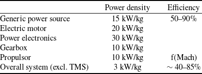
For the propulsion system an exemplary generic and scalable hybrid electric propulsion system with an entry into service of 2035 is assumed for demonstrating purposes of the proposed TMS methodologies only. For the study the efficiency of the generic drive unit, except the propulsor efficiency, is increased stepwise (10% steps) from 50% until 90%. The propulsor efficiency is a function of the Mach Number. Additionally, an overall power-to-weight ratio of 3 kW/kg is applied, which includes the assumptions as listed in Table 2. The power density assumptions for the electric motor, power electronics, gearbox and propulsors were derived from Refs [Reference Plencner, Senty and Wickenheiser23–27].
Assumptions for the generic drive system

The maximum cooling temperature at the outlet of the heat exchanger is assumed to be 333.15 K at each operating point to ensure appropriate cooling temperature for the generic drive system. The inlet temperature of the cooling medium, which is water, is assumed to be 360 K in this study, since a maximum component temperature of 90°C is assumed. The nozzle pressure ratio is set to 1.1 at the design point, and the relative pressure loss in the heat exchanger is set to 2%. Additionally, the diffuser opening angle is assumed to be 12°. If the cooling medium freezes, the nozzle of the TMS system is closed as far as the fan allows to reduce the pressure ratio. A minimum nozzle pressure ratio is set to 1.03. To prevent the cooling medium from freezing, the TMS system is modularised as described in section 3 so that the mass flow per TMS module is reduced; however, the overall mass flow would grow due to higher mass and drag of the overall system. Due to the snowball effect, this is repeated until there are enough nacelles with an integrated TMS system. At the operating points where the cooling medium would freeze, some nacelles can now be closed completely. This reduces the air mass flow but the cooling fluid still runs through all TMS systems. This is the proposed method to prevent freezing. It is assumed that the TMS systems can only be completely closed or completely open, so that entire systems are switched off at the required operating points. The system is now designed according to sections 3.2 and 3.3.
In this study, a figure of merit is established to evaluate the overall system. The figure of merit is the gross performance of the whole system. The gross power is defined by Equation (11).
 \begin{equation}{P_{g,Total}} = {P_{net,Total}}*\frac{1}{{{\eta _{Total}}}}\;\end{equation}
In the following, gross performance is also referred to as total system performance. The ability of an aircraft to fly efficiently and achieve optimum performance is of central importance, as this parameter is also a simplified indicator of environmental impact and operating costs. However, cost and climate impact are not investigated within this work.
5.0 Results
Section 5.1, briefly discusses the impact of heat exchanger design. Using a regional aircraft with 70% propulsion efficiency as an example in this section only, the effect of heat exchanger design on effectiveness is shown for each of the four configurations. The most efficient heat exchanger type is chosen for the described study. Subsequent sections discuss the results at the overall aircraft level.
5.1 Heat exchanger type study
In this preliminary study, a comparative analysis was performed on five heat exchangers for an exemplary application. The study followed identical design criteria and boundary conditions as outlined in sections 3.2, 3.3, 3.4 and 4.0. Specifically, parallel, parallel-cross, counter, counter-cross and cross heat exchangers were studied at three different operating points. The principal concepts of these heat exchangers are visualised in Fig. 8.
Simplified visualisation of the principles of parallel, counter and cross heat exchangers.

Figure 9 visually encapsulates that the MTO condition served as the established design point for all configurations and heat exchanger types. At this point, the effectiveness for every configuration and heat exchanger type remains constant. The off-design characteristics of each design can be read off the graph. In parallel flow heat exchangers (parallel and parallel cross), the hot and cold fluids are introduced on the same side of the heat exchanger and flow in parallel directions. A characteristic of parallel flow heat exchangers is the maximum temperature difference at the inlet. In addition, the temperatures at the outlet can only converge, resulting in pronounced thermal stresses initially due to the large temperature difference. Furthermore, the limited temperature approach at the outlet means that under comparable conditions, parallel flow heat exchangers have the lowest transfer effectiveness, as shown in Fig. 9. It can be seen in Fig. 10, that in counter flow heat exchangers, the two fluid streams enter on opposite sides and flow with a parallel orientation but in opposite directions. This flow configuration provides the most effective heat transfer and the largest achievable temperature changes under comparable conditions. This observation is illustrated in Fig. 9, where the outlet temperature of the cold fluid can exceed that of the hot fluid [Reference Shah15]. In crossflow heat exchangers, hot and cold fluids enter perpendicularly, exhibiting a generalised hybrid characteristic of parallel and counter flow. In this configuration, only portions of the cold fluid at the outlet may have a higher temperature than the hot medium at the outlet. In particular, a one-dimensional description, analogous to the other two types, proves infeasible. In any non-cross-mixed flow, a temperature gradient exists both along and across the flow direction. Complete cross-mixing of material flows eliminates the cross-flow temperature gradient. As a result, the effectiveness of the heat exchanger no longer approximates that of a counter-flow heat exchanger, but approaches that of a parallel flow heat exchanger(Reference Shah15).
Impact on effectiveness for different heat exchanger types and TMS configurations. Also different operating points are visualised.

Impact of the generic drive unit efficiency to total gross system power at MTO conditions within the short-range application.

In the case of the basic ram air TMS, without a fan, counter-flow heat exchangers do not emerge as the most efficient designs. This phenomenon is attributed to increased pressure losses due to increased inlet velocities into the heat exchanger. This phenomenon is achieved when the TMS modules are shut off in the MCL and MCR. When modules are switched off, more heat dissipation is required per module per operating point. This increases the required mass flow per nacelle and, therefore, also the inlet Mach number, which leads to higher pressure losses. There are also noticeable differences between fan configurations. In configurations such as pusher fan and dual fan, the heat exchanger is located behind one fan, resulting in a temperature rise ahead of the heat exchanger. This results in a larger geometry. Due to its increased effectiveness, a cross-counter-flow heat exchanger is used. Notably, cross-counter-flow heat exchangers also manifest the most compact heat exchanger matrix volumes and masses, making this design particularly favoured for the ram air configuration.
5.2 Overall system assessment
This section presents the study results with the boundary conditions and assumptions from section 4. Mainly, the results from the exemplary short-range application are shown. The results of the regional application are summarised in section 5.2.2 with an analysis of the defined target function. In the last sections, the results regarding drag are discussed for the short-range application only.
5.2.1 Target function assessment for the short-range application
In Figs 10 and 11, the total gross power of the overall system for each configuration in the described short-haul application is graphically presented against the generic drive efficiency. Figure 10 corresponds to the MTO operating point, while Fig. 11 pertains to the cruise phase. It is evident that at MTO, the TMS without a fan attains the lowest gross overall system power. Notably, the ram air configuration does not work at low efficiency, below 63%. This limitation is attributed to operational constraints, particularly for lower operational mass flows, within this system. The taxiing operating point was not addressed due to insufficient mass flows. Conversely, configurations with enhanced operational capabilities, such as the TMS with the fan positioned behind the heat exchanger, achieve comparable performance. Under cruise conditions, as depicted in Fig. 11, the ram air configuration emerges as the system with the highest power output. This outcome is ascribed to the configuration’s size, mass and volume, resulting in high aerodynamic drag due to the increased cruise speed, as mentioned in section 5.2.3. The ram air system needs very high mass flows to dissipate the heat also at very low speeds, e.g., taxiing. The advantageous features of the puller fan configuration lie in its improved temperature ratio compared to the pusher fan, as the air side is not preheated before the heat exchanger. Furthermore, the mass flow through the system is increased, which leads to reduced heat transfer areas and a reduced fan power demand. Additionally, this system can be designed more compact due to the fan behind the heat exchanger. Furthermore, the incorporation of a fan in the system provides the capability to influence the entry conditions into the heat exchanger, thereby maintaining low system pressure losses. The drawbacks of the pusher fan, as detailed in section 2.1, are also discernible in Figs. 10 and 11. The fan preceding the heat exchanger results in an elevated temperature before the heat exchanger, contributing to an increased size and weight of the TMS system. This compensates for the inferior temperature ratio through higher mass flows. However, pressure losses remain low due to the installation of radiators. The dual fan system is close to the system power of the puller fan in cruise, because the fans are generating more thrust since both fans have a pressure ratio of 1.2, so in total 1.44. The single-fan configurations have therefore 17% less pressure ratio increase.
Impact of the generic drive unit efficiency to total gross system power at MCR conditions within the short-range application.

In this study, the thrust generated by the TMS is included in the overall thrust equilibrium of the system. This inclusion allows the primary propulsion system to be more compact, especially when the thrust output exceeds the drag forces induced by the nacelle. The integrated fans provide additional thrust. Figures 12 and 13 illustrate the proportional relationship between the thrust contribution of the thermal management system and the propulsion system, depending on the generic drive efficiency in the context of a short-range application. The increased heat demand resulting from increased power requirements results in a pronounced thrust contribution from the TMS system, especially at low efficiencies. In particular, the ram air TMS configuration without a fan generates only aerodynamic drag without any concurrent thrust production. Conversely, the dual fan system provides significant thrust contributions due to its increased overall compressor pressure ratio (1.2 each). The pusher fan generates increased thrust utilising its higher temperature level. On the other hand, the puller fan, characterised by its compact design, has a lower aerodynamic drag and a lower weight compared to the other configurations. During the cruise phase, characterised by high speeds in the short-range application, the thrust contributions are negated by increased drag. Figure 13 illustrates the cruise conditions and shows a significant increase in drag for the ram air configuration. The drag increases as the primary objective of the main propulsion system shifts to overcoming the drag forces imposed by the TMS. Other configurations also experience significant increases in drag. The dual fan configuration shows an increased thrust contribution due to increased pressure levels. The Meredith effect can be exploited in MTO in configurations with a fan. The effect supports cruising flight, but it is not sufficient to overcome the drag completely.
Thrust ratios between TMS thrust and propulsion thrust at MTO conditions within the short-range application.

Thrust ratio between TMS thrust and propulsion thrust at MCR conditions within the short range application.

A further metric supporting to evaluate the TMS is shown in Figs 14 and 15. The figures show the relationship between total gross power and total generated thrust for MTO and MCR for short-haul applications. For each configuration, it is shown how much power per thrust is required to operate the aircraft at each operating point. At both operating points, the fan configurations are significantly lower than the ram air TMS. At cruise, this is mainly due to the high drag, which is not compensated. The dual fan configuration is the most efficient due to the high thrust component. The total power to total thrust parameter can also be used as an efficiency metric for the integrated TMS at the overall system level.
Total system power to total system thrust at MTO within the short-range application.

Total system power to total system thrust at MCR within the short-range application.

Figure 16 visualises the mass of the TMS per nacelle for all four configurations and the different generic drive efficiencies. It shows that the mass does not decrease linearly as the efficiency increases. This is due to both snowball effects and to the power increases with 1/ETA. It can be seen that the systems with low efficiencies have very high TMS masses and, therefore, the system increases significantly in total mass and thrust. The ram air configuration shows the lowest masses, as no additional fan and fewer snowball effects occur here, as no installed fan requires additional power. The weight increases are outside a realistic range at the low efficiencies. This investigation is therefore suitable for theoretical purposes in order to visualise the effects of integrating a TMS.
Installed TMS mass per TMS module for all four configurations at different generic drive efficiencies for the short-range application.

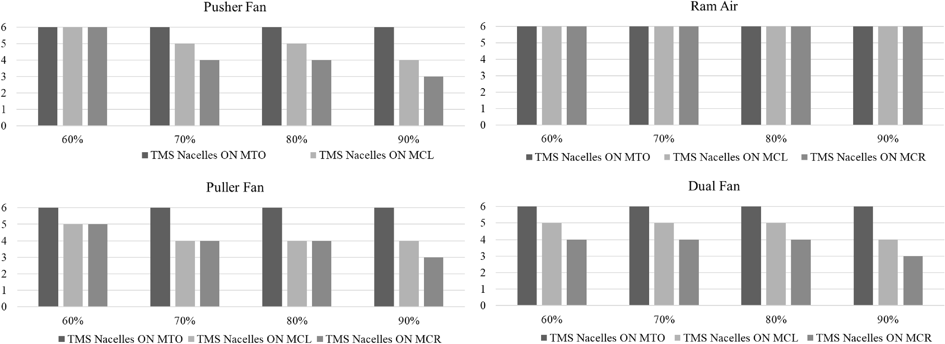
Figure 17 shows how many TMS modules are switched off for which configuration. It can be seen that at low efficiency levels, few modules can be switched off along the mission. In the ram air configuration no module is switched off. The other systems switch off 2–4 modules along the mission. Due to the lower power requirement, at least one module is switched off in MCL and usually two modules in MCR. The puller fan does not have to switch off another module at 70% and 80% efficiency, even in cruise.
Overview of TMS nacelles, which are switched on in different operating points for the different configurations and generic drive efficiencies for the short-range application.

5.2.2 Target function assessment for the regional application
Figures 18 and 19 summarise the results for the regional application class. It shows the total gross power of the entire system for each configuration of the described regional application over the generic propulsion efficiency. The configurations are similar to the short-haul application, except for the ram air configuration. This configuration is as efficient in cruise as the puller fan configuration in the total system view. This is primarily due to the cruise speed and associated low power requirement and low drag. Since drag is square proportional to speed, the total gross power will increase significantly in applications with higher cruise speeds. It can also be seen that even in the regional application, the operational capability is particularly limited while taxiing. The ram air configuration can no longer perform taxiing on the runway at efficiencies below 57%. This is due to the low air speeds at this operating point resulting in a too small heat capacity on air side. Due to the snowball effects and the fact that the gross thrust increases with
 $\frac{1}{{{\eta _{Total}}}}$
, see Equation (11), the required power increases exponentially for both regional and short-haul applications.
Impact of the generic drive unit efficiency to total gross system power at MTO conditions within the regional application class.

Impact of the generic drive unit efficiency to total gross system power at MCR conditions within the regional application class.

5.2.3 Drag assessment
Figures 20 and 21 depict the calculated aerodynamic drag of the TMS nacelle for each short-range mission configuration for MTO and MCR. The figures show the high drag of the ram air configuration, which rises sharply due to the snowball effects, especially at low system efficiencies. It can be seen that the puller fan features the TMS system with the lowest drag. The low power requirement of this configuration results in a more compact design and thus low friction drag. In addition, this system can partially compensate for the aerodynamic drag by the Meredith effect.
TMS nacelle drag for different generic drive efficiencies at MTO conditions within the short-range application class.

TMS nacelle drag for different generic drive efficiencies at MCR conditions within the short-range application class.

6.0 Conclusion
This study describes design guidance for sizing a generic thermal management system using a successful implementation of a multi-design point technique. Four different TMS configurations were developed for two different mission profiles and aircraft categories with generic hybrid electric propulsion systems. The optimisation objective focused on total gross performance, which served as an initial, foundational metric for assessing cost implications and environmental impact.
Two mechanisms were introduced to avoid coolant freezing in certain operational scenarios. Duplication and dispersion of the thermal system provide the ability to selectively shut down individual TMS modules. Improved operability is achieved through a variable nozzle and the incorporation of one or two fan stages.
An investigation of the effect of heat exchanger design on overall system-level effectiveness resulted in the selection of a cross-counter flow-heat exchanger due to its superior temperature conditions.
The results indicate that the puller fan configuration is the most efficient in terms of total system power for the short-range application, although it is not the lightest. This configuration minimises total system power by taking advantage of favourable temperature differentials and utilising the Meredith effect, providing increased operating capability and overcoming problems encountered by the ram air at certain operating points. Dual fan configurations, characterised by a high-pressure ratio, provide significant thrust components, but offer no additional benefits due to the increased mass and temperature disadvantages of the fan in front of the heat exchanger. The pusher fan configuration, positioned between the dual fan and the puller fan, provides an intermediate performance in terms of overall system performance. For the regional application also a ram air configuration can be realised due to low installation drag and low masses.
In summary, the study emphasises the critical consideration of all effects, especially nacelle drag, in the thermal management system design process. It also emphasises the need to consider sensitivities such as drag, mass, pressure drop and efficiency during the design phase, recognising that the optimal TMS may not be the lightest or lowest pressure drop configuration. Future research will explore optimisations such as variations in pressure losses within the heat exchanger system, water injection into the heat exchanger during takeoff, implications of pressure increase due to propellers or the design and integration of TMS configurations tailored to specific operating points.
Acknowledgments
The authors would like to thank MTU Aero Engines for the permission to publish this paper.