Nomenclature
-
 $D$
-
damping matrix
-
${F_{Aero}}$
-
aerodynamic forces
-
$K$
-
stiffness matrix
-
$M$
-
mass matrix
-
$Q$
-
aerodynamic forces matrix
-
${R_l}$
-
aerodynamic states vector
-
${U_\infty }$
-
flight speed
-
${b_{l\;\;}}$
-
aerodynamic pole
-
$c$
-
reference chord
-
$f$
-
frequency
-
$q_{dyn}$
-
dynamic pressure
-
$t$
-
time
-
$w$
-
gust vector
-
${\rm{\Delta }}T$
-
time window
-
$\delta $
-
control surfaces vector
-
$\xi $
-
generalised coordinates
-
$\phi $
-
Spoiler deflection ramp function
-
$\sigma $
-
spoiler deflection
-
$\tau $
-
non-dimensional time
-
$\omega $
-
angular velocity


Subscripts
-
$LAF$
-
spoiler
-
$g$
-
gust
-
$x$
-
control surface
-
$intcp$
-
intercept


Superscript
- -
-
generalised
- ∼
-
fourier transform
- .
-
time first derivative
- ..
-
time second derivative
1.0 Introduction
As the global population and economic activities continue to expand, the aviation industry faces escalating pressure to address its environmental footprint since it currently contributes approximately 2–3% of global carbon emissions, and such a share is destined to rise with increasing flight volumes in the years to come. Therefore, pioneering sustainable aviation has become imperative in order to align with international climate goals and meet the growing societal demand for environmentally responsible travel.
Recent advancements in technology and policy have begun to pave the way for more sustainable aviation practices with the goal of achieving net-zero emissions by 2050 [1]. Such an ambitious goal is fraught with technological and engineering challenges and will be achieved via a number of strategic steps including: the progressive integration of sustainable aviation fuels (SAF); improved operational strategies such as optimised flight paths and air traffic management; and the development of new fuel-efficient aircraft design.
Aircraft flight and ground loads are key elements in aircraft structural sizing, directly determining its weight. To minimise costs and fuel consumption, aircraft designers aim for minimum structural weight while ensuring no failure occurs during an aircraft’s operation and in-service life due to excessive stresses or deflections. Aircraft load alleviation strategies are of particular interest since they allow the mitigation of critical load cases, thus preventing over-sizing the structure.
Active load alleviation devices were developed and applied earlier in the aeronautical industry compared to passive approaches. The use of isotropic materials (mostly aluminium alloys), standard wing structural elements (primarily spars with transverse ribs), fixed wing geometries (without morphing) and a more conservative design approach has led to the construction of stiff aircraft structures. This resulted in rather small deformations, which limited the exploitation of flexibility effects characteristic of passive load alleviation strategies.
Regan and Jutte [Reference Regan and Jutte2] provide a thorough survey of key milestones in active system development, demonstrating that aeroservoelastic effects can be exploited for various objectives. These include alleviating peak gust and manoeuvrer loads, mitigating load cycles to enhance fatigue life, improving flight handling qualities, reducing and controlling structural deformation and suppressing flutter. Forward and aft wing-tip vertical accelerometers, as well as fuselage vertical accelerometers and pitch gyroscopes, were used to measure the bending and torsional wing motion together with the overall aircraft vertical displacement and pitch rotation. This information was used to control the deflection of the aerodynamic control surfaces in order to vary the wing lift distribution, thus reducing the loads. Inner and outer spoilers as well as ailerons were deflected upward in order to reduce the wing lift for discrete gust and manoeuvre loads mitigation, whereas both an upward and downward deflections were allowed for flutter suppression and fatigue loads reduction during turbulence [Reference Karpel3, Reference Norman4].
Significant research has been carried out at the University of Bath, investigating the use of ‘mini-spoilers’ or ‘mini-tabs’ to reduce aircraft loads during gust and manoeuvrers [Reference Cleaver, Chiereghin, Heathcote, Bull and Gursul5–Reference Heathcote, Gursul and Cleaver10]. The studies have systematically investigated the optimal chordwise location and height of these mini-spoilers for maximum lift reduction and load alleviation. Trailing-edge placement is generally effective at low angles of attack. As the angle-of-attack increases, the optimal location for lift reduction tends to move towards the leading edge. Mid-chord locations have also been shown to provide consistent performance over a range of angles of attack. Leading-edge mini-spoilers can be particularly effective at higher angles of attack by inducing flow separation and reducing the lift slope, which is beneficial in gust encounters.
More recently Hadjipantelis et al. [Reference Hadjipantelis, Son, Wang and Gursul11, Reference Hadjipantelis, Wang and Gursul12] focused on the loads alleviation performance of the mini-tabs, particularly during plunging motions (simulating the wing response to a gust) and in response to vortical gusts. These papers demonstrate that the effectiveness of mini-spoilers depends on the reduced frequency of the unsteady wing motion. Generally, their ability to alleviate loads decreases as the frequency of oscillation increases, compared to a steady condition. The interaction of the spoiler-induced flow separation with the leading-edge vortex dynamics is a critical aspect. Leading-edge spoilers can influence leading-edge vortex formation, while trailing-edge spoilers may become engulfed in separated flow, limiting their effectiveness under highly unsteady conditions.
The impact of wing sweep on spoiler effectiveness is also a key research area [Reference Hadjipantelis, Son, Wang and Gursul11, Reference Hadjipantelis, Wang and Gursul12]. Increased sweep angles can diminish the effectiveness of trailing-edge spoilers due to intensified spanwise flow. The performance of leading-edge spoilers can also be affected by sweep, with phenomena like the formation of a tip vortex at the spoiler’s inboard edge influencing the flow reattachment.
Ajaj et al. [Reference Ajaj and Djidjeli13] proposed a ‘reverse hinge spoiler’. Unlike conventional spoilers that are hinged at their front and rotate forward (towards the leading edge of the wing), this novel design is hinged at its rear and rotates backward (towards the trailing edge of the wing). The proposed reverse hinge spoiler demonstrated a larger increase in drag and a sharper reduction in lift compared to a conventional spoiler. This improved performance was observed across a wide range of spoiler deflection angles and flight conditions. The study found that reversing the hinge direction causes a higher adverse pressure gradient in front of the spoiler. This is because the reverse hinge spoiler ‘traps’ more airflow compared to a conventional spoiler. This is the primary reason for the increased drag and reduced lift characteristics of the novel design, making it potentially more effective for flight load control.
Passive load alleviation strategies are of particular interest because they mitigate aircraft loads without relying on active devices, thereby limiting required activation power and reducing failure risks. However, these kinds of passive approaches exploit fluid-structure interaction effects to reduce structural loads, meaning their performance may not be satisfactory across all points of the flight envelope. Aeroelastic tailoring is an example of passive load alleviation, defined as ‘the incorporation of directional stiffness into an aircraft structural design to control aeroelastic deformation, static or dynamic, in a way that beneficially affects the aircraft’s aerodynamic and structural performance’ [Reference Weisshaar14, Reference Weisshaar15]. The basic idea behind aeroelastic tailoring consists of designing a wing structure that, when deformed under the action of external loads, generates an incremental aerodynamic loads distribution partially mitigating the structural loads. This is, in general, achieved through the coupling of the wing bending and torsional motions. A typical example is given by sweptback wings since the sweep angle introduces a geometric coupling between the bending and the pitching motions. Control and optimisation of the bending torsion coupling can also be achieved through the use of anisotropic materials, such as composite materials. A number of research activities have proposed the optimisation of the stacking sequence of composite material layers with different thickness and fibres orientation in order to achieve the desired stiffness tailoring [Reference Weisshaar14, Reference Weisshaar15]. More recently, Stodieck et al. have also investigated the use of tow-steered composites, consisting of laminates with variable angle tow plies allowing curvilinear fibres paths and thus a continuous stiffness variation within each ply [Reference Stodieck, Cooper, Weaver and Kealy16].
Similar coupling effects can also be allowed by the use of innovative structural shapes and arrangements. A number of works [Reference Abdelkader, Harmin, Cooper and Bron17–Reference Locatelli, Mulani and Kapania19] have shown how aeroelastic tailoring effects can be enhanced by using curvilinear spar and rib elements or by varying the spar/ribs orientation along the wing span for both static and dynamic applications.
A recent consideration in aircraft design is the use of novel configurations, such as the NASA and Boeing truss-braced wing aircraft concept [Reference Chen, Zhou, Ghoman and Falkiewicz20–Reference Zhao, Kapania, Schetz and Coggin22], always with the aim of enabling an improvement of the aerodynamic efficiency with a limited repercussion on the structural weight.
This paper investigates a novel load alleviation technology called Superelastic Monostable Spoiler (SMS) [Reference Cosentino and Llewellyn-Jones23] recently studied by Wheatcroft et al. [Reference Wheatcroft, Shen, Groh, Pirrera and Schenk24, Reference Wheatcroft, Mahadik, Groh, Pirrera and Schenk25] who proposed a structural arrangement characterised by sequential instabilities in order to achieve a passively actuated spoiler-type system. The main idea consists of having a chain of elements prone to buckling that would snap under the compression load induced by wing motion during a gust or a manoeuvrer. The chain of structural instabilities is exploited to activate a spoiler-like device, which in turn leads to local lift reduction. If properly sized, the SMS would enable spoiler actuation only when the local structural strain is higher than a specific threshold, thus enabling deployment only for high-load events while keeping the spoiler stowed under normal cruise conditions.
This work presents a preliminary investigation of the use of the SMS for dynamic loads reduction. The study focuses on the dynamic behaviour of the spoiler during gust-induced actuation and retraction cycles and the related impact on the overall wing loads. A number of trade studies are presented, investigating different SMS activation thresholds and spoiler deflection rates. This paper does not deal with the detailed structural and mechanical design of the SMS, which will be addressed in future works. The reported results show promising gust loads alleviation capability.
2.0 Mathematical modelling
A representative civil aviation model, as shown in Fig. 1, is used for this work. The structure is modelled via a linear finite element model with lumped masses, and the aerodynamic forces are determined using the doublet lattice panel method [Reference Albano and Rodden26]. The stiffness, mass and aerodynamic matrices are extracted from the commercial software MSC Nastran using dedicated DMAP (Direct Matrix Abstraction Program) sequences. Aerodynamic corrections are also introduced in order to account for the correct lift and pitch moment distribution along the wing.
Structural model.

The dynamic equation of motion can be described in the time domain as follows:
 \begin{align}\bar M\ddot \xi + \bar D\dot \xi + \bar K\xi = {\bar F_{Aero}}\end{align}
where
 $\bar M$
,
 $\bar D$
and
 $\bar K$
are the generalised mass damping and stiffness matrices, respectively. The generalised aerodynamic forces are defined in the frequency domain as
 \begin{align}{\bar F_{Aero}} = {q_{dyn}}\left[ {Q\left( {{M_{ach}},k} \right)\tilde \xi + {Q_g}\left( {{M_{ach}},k} \right)\tilde w + {Q_x}\left( {{M_{ach}}} \right)\tilde \delta + {Q_{LAF}}\left( {{M_{ach}}} \right)\tilde \sigma + {Q_{intcp}}\left( {{M_{ach}}} \right)} \right]\end{align}
where
 $Q$
 $\left( {{N_{Modes}} \times {N_{Modes}}} \right)$
,
 ${Q_g}$
 $\left( {{N_{Modes}} \times {N_{Panels}}} \right)$
,
 ${Q_x}$
 $\left( {{N_{Modes}} \times {N_{ControlSurf}}} \right)$
and
 ${Q_{LAF}}$
 $\left( {{N_{Modes}} \times 1} \right)$
are respectively the generalised aerodynamic forces matrices related to the Fourier Transform of the generalised coordinates
 $\tilde \xi $
, gust vector
 $\tilde w$
, control surfaces vector
 $\tilde \delta $
and spoiler deflection
 $\tilde \sigma $
;
 ${Q_{intcp}}$
 $\left( {{N_{Modes}} \times 1} \right)$
is a constant term accounting for the wing twist and aerodynamic profiles’ camber effects; whereas
 ${q_{dyn}} = \frac{1}{2}\rho U_\infty ^2$
is the dynamic pressure.
The aerodynamic matrices
 $Q$
and
 ${Q_g}$
were computed for a limited number of reduced frequencies
 $k = \frac{{\omega c}}{{2{U_\infty }}}$
(where
 $c$
is the reference chord,
 ${U_\infty }$
the flight speed and
 $\omega $
the angular velocity) and at a given Mach number. To allow for simulation in the time domain, the aerodynamic matrices were approximated, in the frequency domain, using the rational fraction approximation method proposed by Roger [Reference Roger27]. Following some manipulation, the aerodynamic loads can be formulated in the time domain as
 \begin{align} &{{\bar F}_{aero}} = {q_{dyn}}\left\{ \left[ {{Q_0}\xi + {Q_1}{c \over {2{U_\infty }}}\dot \xi + {Q_2}{{\left( {{c \over {2{U_\infty }}}} \right)}^2}\ddot \xi } \right]\right. \nonumber\\ &\quad\qquad+ \left[ {{Q_{g0}}w + {Q_{g1}}{c \over {2{U_\infty }}}\dot w + {Q_{g2}}{{\left( {{c \over {2{U_\infty }}}} \right)}^2}\ddot w} \right]\nonumber\\ &\quad\qquad\left.+ {Q_x}\delta + {Q_{LAF}}\sigma + {Q_{intcp}} + \mathop \sum \limits_{l = 1}^{{N_{Poles}}} {R_l}\right\} \end{align}
where
 ${R_l}$
 $\left( {{N_{Modes}} \times 1} \right)$
is the generic aerodynamic state vector related to the generic lag-pole
 ${b_l} = {k_{max}}/l$
. These extra states allow the modelling of the unsteady aerodynamics by taking into account the delay of the aerodynamic forces with respect to the structural deformations. These aerodynamic states are evaluated through the set of dynamic equations
 \begin{align}{\dot R_l} = - {b_l}\frac{{2{U_\infty }}}{c}I{R_l} + Q_{2 + l}^\xi \dot \xi + Q_{g2 + l}^w\dot w{\rm{\;\;\;\;\;\;\;\;\;\;\;\;\;\;\;\;\;\;\;\;\;\;\;\;}}l = 1 \cdots {N_{Poles}}.\end{align}
It is important to point out that only unsteady aerodynamic effects due to structural deformation and gust are considered, whereas the aerodynamic forces due to the control surface and the SMS deflection are assumed to be quasi-steady. Future work will focus on the modelling of the unsteady spoiler aerodynamic forces based upon the experimental works from Hadjipantelis et al. [Reference Hadjipantelis, Son, Wang and Gursul11]. The generalised incremental aerodynamic forces due to a unitary SMS deployment,
 ${Q_{LAF}}\left( {{M_{ach}}} \right)$
, are computed by correcting the doublet lattice aerodynamics according to reference incremental wing lift and pitching moment values computed via a rigid and steady CFD calculation with the spoiler fully deployed. The evolution of the SMS induced aerodynamic forces during the passive extension and retraction is modelled as
 \begin{align}{F_{LAF}} = {Q_{LAF}}\sigma \left( t \right) = {Q_{LAF}}{\sigma _{ref}}\phi \left( t \right)\end{align}
where
 ${\sigma _{ref}}$
is the spoiler reference deflection for which the aerodynamic data have been computed, and
 $\phi\!\left( t \right)$
is a linear ramp function that scales the spoiler deflection and its related incremental aerodynamic contribution. Such a ramp-up function is defined as follows during spoiler extension:
 \begin{align*}\left\{ {\begin{array}{*{20}{l}}{\phi = 0.} {}{{\rm{\;\;\;\;\,\,\,\,\,\,\,\,\,\!}}if{\rm{\;\;\;\;}}t \lt {t_{trigger}}}\\{0 \le \phi \le 1.} {}{{\rm{\;\;\;\;}}if{\rm{\;\;\;\;}}{t_{trigger}} \le t \le {t_{trigger}} + {\rm{\Delta }}{T_{deployment}}}\\{\phi = 1.} {}{{\rm{\;\;\;\;\,\,\,\,\,\,\,\,\,\!}}if{\rm{\;\;\;\;}}t \gt {t_{trigger}} + {\rm{\Delta }}{T_{deployment}}}\end{array}} \right.\end{align*}
whereas for a retraction it is defined as:
 \begin{align*}\left\{ {\begin{array}{*{20}{l}}{\phi = 1} {}{{\rm{\;\;\;\;\;\;\,\,\,\,\,\,\,\,}}if{\rm{\;\;\;\;}}t \lt {t_{trigger}}}\\{1 \geqslant \phi \geqslant 0.} {}{{\rm{\;\;\;\;}}if{\rm{\;\;\;\;}}{t_{trigge}} \le t \le {t_{trigger}} + {\rm{\Delta }}{T_{deployment}}}\\{\phi = 0.} {}{{\rm{\;\;\;\;\,\,\,\,\,\,\,\,\,\!}}if{\rm{\;\;\;\;}}t \gt {t_{trigger}} + {\rm{\Delta }}{T_{deployment}}}\end{array}} \right.\end{align*}
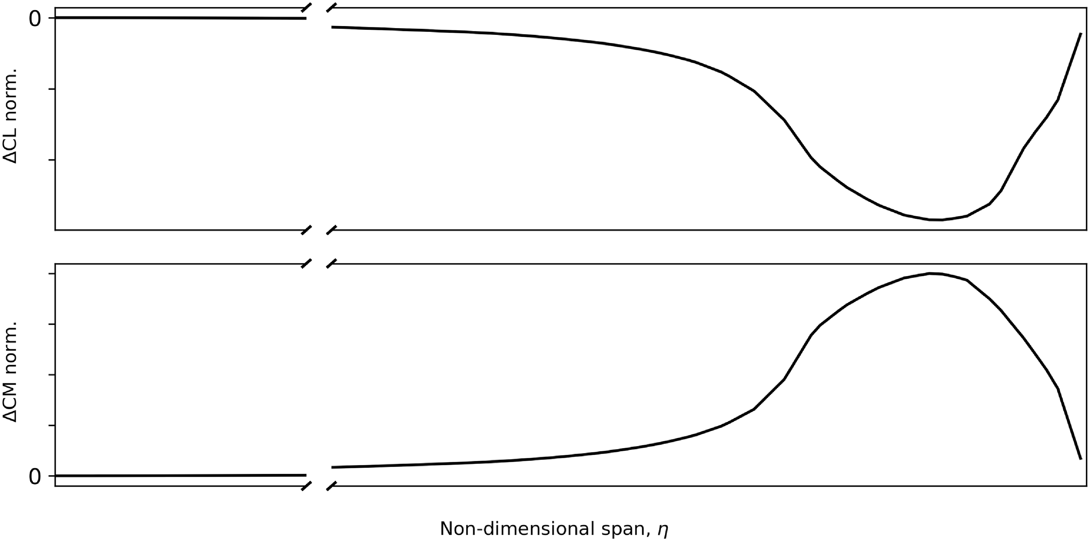
In this work, the SMS is assumed to be placed in the outer part of the wing, between 70% and 100% span, with a chord-wise and span-wise length comparable to the standard dimensions of a typical aileron (between 15% and 25% of the wingspan). Figure 2 reports an example of the incremental spanwise aerodynamic loading distribution due to the spoiler deployment.
Incremental aerodynamic loading distribution due to the spoiler deployment.

3.0 Numerical results
This paper focuses on analysing the SMS loads alleviation performance during gust conditions only since it is assumed that such a technology would definitively provide good manoeuvrer loads alleviation capability. The research question is whether a passively actuated device would be capable of providing satisfactory loads alleviation performance during a dynamic event for which the timing and reactivity of the movable is essential. This work primarily investigates the actuation strategy and its impact on load-alleviation performance. To isolate this element, the SMS is compared with a standard ‘sensor+actuator’-based system. Both systems use the same aerodynamic surface, ensuring identical aerodynamic effects at full spoiler deployment. Consequently, any observed differences in results are solely attributable to the contrast between passive and active actuation modes.
The dynamic gust response analyses are performed from a trimmed ‘1-g’ flight configuration, as the SMS deployment is driven by the total loading status of the structure, not just the dynamic increment. It is essential to clarify that this methodology does not introduce any geometric non-linear effects, from either a structural or aerodynamic perspective. Therefore, phenomena such as aerodynamic follower forces, pre-stressed modal shapes, the projection of the gust downwash on the deformed shape, and the updating of aerodynamic matrices to capture the trimmed deformation are excluded due to the preliminary nature of this study and will be addressed in future work. Instead, the aircraft’s trim is determined through a static solution of Equation (1), where the angle-of-attack and elevator deflection are adjusted as unknown variables to balance the aircraft weight and pitch moment under a specified 1g loading factor.
Several gust response analyses were conducted, assuming a ‘1-cosine’ gust profile over a range of gust lengths (between 18 and 214 m) and intensities, according to European Aviation Safety Agency (EASA) Regulation [28], as well as a continuous turbulence gust case derived from real flight test measurements. Three mass cases were considered, ranging from an Operative Weight Empty (OWE) to Maximum Take-Off Weight (MTOW), along with four flight points along the cruise speed curve from sea level to cruise altitude.
The finite element model used for the investigation is representative of the global aircraft dynamics; however, it is not suitable for accurately representing local stress distribution. Therefore, an approximation is introduced regarding the SMS trigger logic: the SMS is deployed and retracted based on the local wing displacement relative to the wing root, rather than local wing strain. Despite the two quantities showing a degree of correlation, the latter is what would, in reality, determine the SMS behaviour. Nevertheless, given the preliminary nature of this study, monitoring the wing displacement was assumed to be a reasonable assumption that would not change the qualitative findings of this work.
All the reported results have been normalised as follows:
-
• The bending moment values are normalised with respect to the wing root bending moment limit load (WRBM-LL). This is the maximum WRBM experienced by the aircraft across all mass cases, gust lengths and flight points considered in this study.
-
• The non-dimensional time is normalised with respect to the first wing bending moment frequency as
$\tau = t\,{\rm{*}}\,{f_{{1^{st}}WingBendingMode}}$
. -
• The wing span-wise position is normalised against the wing semi-span.

To validate the time-marching formulation, the aircraft’s dynamic response to several gust lengths was compared against reference Nastran calculations. For the Nastran reference, all structural modes between 0 and 100 Hz were included, using a frequency step of 0.01 Hz. In contrast, the time-domain simulation assumed a 0.01 s time step, five aerodynamic poles and the same number of structural modes. Figure 3 compares the normalised wing root bending moment from the present formulation with the Nastran reference. The results demonstrate a satisfactory approximation of structural dynamics and unsteady aerodynamic effects, aligning with previous findings [Reference Castrichini29].
Comparison of the normalised wing root bending moment from the present work, using a Roger’s RFA time marching gust formulation, against a reference Nastran simulation.

In the following section, the SMS load alleviation performance for each case is compared against two models: a baseline model with no Load Alleviation Function (LAF) and a model where the SMS is deployed in a manner similar to a typical LAF based on actuated movables. In the latter, once a gust is detected by sensors like alpha vanes or accelerometers, an actuator signal commands the movable’s deployment. The movable then deploys at a certain speed, consistent with modern actuator performance, and remains deflected at a constant angle throughout the entire load event. Such a comparison allows assessment of the SMS LAF performance against a movable that produces the same aerodynamic incremental forces but is actively actuated.
Since the SMS is a passive load alleviation device, its load alleviation capabilities are not expected to be as effective as those of actuated LAF strategies. Due to the sudden and dynamic nature of a gust encounter, effective gust alleviation technologies require the capability to detect the gust and deploy the LAF-related control surface as quickly as possible, aiming to develop gust-adverse incremental aerodynamic forces before the gust produces peak wing loads. On the other hand, the SMS is actuated by gust-induced wing strain; therefore, its deployment is expected to occur after the gust has already produced maximum loads at the wing root. This is particularly true for a modern civil aircraft with a swept-back wing, where an SMS located close to the wing tip would experience gust-induced strain, and thus deploy, after the gust has already passed the majority of the wing. Figure 4 reports the wing-bending moment envelope due to the different load cases considered, as well as the time histories of the wing root bending moment and the related spoiler deployment for a single flight, point mass case, and gust length. The spoiler deployment plot shows curves that can evolve linearly between 0 (undeployed) and 1 (fully deployed). A number of different wing-tip displacement thresholds are investigated, ranging from 40% to 54% Limit Displacement (LD). Similar to the LL, the LD is the maximum displacement, evaluated at the spoiler location relative to the wing root, experienced by the aircraft for all loading conditions assumed in this work. The SMS is assumed to deploy [retract] as soon as the wing tip exceeds [falls below] the selected displacement threshold. The spoiler deployment and retraction speeds are assumed to be the same and constant for all cases.
SMS dynamic response for different wing-tip displacement thresholds and a fixed deployment/retraction rate equal to 250% of the actuated LAF speed.

The results show that the lower the threshold value, the earlier the spoiler deploys, leading to better load alleviation. For lower wing-tip displacement thresholds, the spoiler exhibits better load alleviation when compared to typical actuated LAF, whereas little to no load alleviation is observed for higher threshold values. As expected, for the higher actuation threshold, the spoiler deploys too late and does not have enough time to counteract the gust-induced loads, especially at the wing root. Moreover, unlike typical actuated LAF, the SMS does not increase negative loads compared to the baseline model, as it tends to retract before gust-induced negative peak loads occur. Undesired post-gust SMS-induced wing oscillations are observed for lower actuation thresholds. This is because, after the dynamic gust event, the wing tends to oscillate around the actuation threshold value (which, in lower cases, is just above the 1g level), thus leading to undesired spoiler deployment and retraction, which in turn causes further wing oscillation and spoiler activation.
Figure 5 reports a similar investigation, but this time for a number of different deployment and retraction speeds. For all cases, the SMS is assumed to deploy [retract] as soon as the wing-tip exceeds [falls below] the 42% LD threshold. Deployment and retraction speeds are assumed to be the same.
SMS dynamic response for different deployment and retraction speeds and a fixed displacement threshold of 42% LD.

The results show that the faster the spoiler deployment speed, the better the load alleviation performance. For lower deployment speeds, the spoiler exhibits better load alleviation when compared to the actuated LAF, whereas for lower actuation speeds, little to no load alleviation is observed. However, it is also observed that a quick spoiler deployment produces an initial load increment due to the impulsive inertia loads generated by the sudden dynamics. Also in this case, undesired self-induced wing oscillations are observed at certain activation speeds.
Figure 6 builds upon Fig. 5, illustrating how different mass scenarios affect the SMS dynamic response to a discrete tuned gust. Notably, the SMS remains inactive for the lightest mass case because the combined displacement from the gust and steady 1g flight does not exceed the study’s 42% limit displacement threshold. Conversely, the SMS activates for heavier mass cases. Notably, for the highest mass case, self-sustained oscillations persist even after the initial gust-induced dynamic response has subsided. This occurs because the 1g loading causes a deformation that is just below the SMS activation threshold; consequently, wing oscillations tend to trigger the SMS even after the gust has passed.
‘1-cosine’ SMS dynamic response and wing root bending moment for different deployment and retraction speeds, a fixed displacement threshold of 42% LD and different mass cases.

SMS dynamic response for different deployment and retraction speeds and a fixed displacement threshold of 42% LD for a continuous turbulence gust.

SMS dynamic response for different wing-tip displacements threshold retraction values, a fixed displacement threshold of 42% LD and a fixed deployment/retraction rate equal to 250% of the actuated LAF speed for a continuous turbulence gust.

Figure 7 shows the same study as in the previous case, but this time for a continuous turbulence gust. In this case, very poor load alleviation performance is observed for the SMS, regardless of how quickly it is actuated. In some cases, the SMS even leads to higher loads when compared to the baseline model, thus increasing the loads instead of alleviating them. Such unexpected behaviour can be understood by examining the time histories of the wing root bending moment and spoiler deployment in Fig. 7. Every time the spoiler deploys, it generates a negative incremental aerodynamic load that pushes the wing downward. Thus, the wing absorbs elastic energy that is released as soon as the spoiler returns to its stowed configuration. The wing will then swing back upward more significantly than it would have otherwise, leading to higher positive loads and upward wing bending deflection, which in turn activates the spoiler again. Despite the SMS successfully reducing the first gust-induced peak loads, it can be concluded that in continuous turbulence, repeated spoiler deflection and retraction can tune with the wing bending dynamics and lead to an amplification of wing oscillation and loads.
SMS dynamic response for different retraction speeds, a fixed displacement threshold of 42% LD and a fixed deployment rate equal to 250% of the actuated LAF speed for a continuous turbulence gust.

Such an undesired effect can be mitigated by preventing the SMS from exciting the wing bending mode while still counteracting the gust-induced loads. A possible solution could be the design of an SMS that exhibits different wing-tip displacement thresholds and/or different speeds between deployment and retraction.
Figure 8 shows a study where the deployment and retraction speeds are kept constant: the SMS is assumed to deploy at 42% LD while the retraction threshold is varied between 40% and 10% LD. It is shown that, for the range of values considered, lowering the retraction threshold has little impact on the undesired SMS-induced wing dynamics and loads. It is also important to point out that a very low or even negative retraction threshold would increase the risk of the SMS remaining deployed after the gust event, with a negative impact on aerodynamic drag and fuel burn performance.
An alternative strategy could be to allow much slower retraction speeds in order to mitigate the wing upward swing after the spoiler retraction. A study is reported in Fig. 9 for different spoiler retraction rates while the spoiler actuation threshold and deployment speeds are fixed. The results do indeed show that the slower the spoiler retraction, the less the SMS-induced wing oscillation and the better the load alleviation performance.
4.0 Conclusions
This paper has provided a preliminary investigation into the use of the Super Elastic Monostable Spoiler for passive gust loads alleviation device. The work focused mainly in understanding the dynamic behaviour of such a device and how it would influence the wing loads during dynamic gust cases.
A number of studies have been introduced by varying the spoiler deployment and retraction speed as well as activation/retraction thresholds. It was shown that the SMS can provide similar loads alleviation capabilities compared with standard LAF strategy. The best performance has been observed when the SMS deploys as early and as quickly as possible while retracting slowly in order to avoid undesired self-induced wing dynamic vibration.
Future studies should consider different spoiler dimensions, numbers and locations (both span-wise, chord-wise and upper/lower surface) to identify the optimal spoiler architecture. The modelling of non-linear unsteady aerodynamics induced by spoiler activation, as well as non-linear structural effects, was beyond the scope of this preliminary investigation and should be included in future work. Finally, a more representative finite element model should be used to allow deployment and retraction modelling based on local strain rather than global wing-tip displacement.
A. Appendix
DLM aerodynamic corrections
With reference to Equation (2) the generalised aerodynamic forces matrices can be defined as follows [Reference Rodden and Johnson30]
 \begin{align}\begin{array}{*{20}{l}}{Q = {\rm{\Phi }}_{ah}^TG{{_{ka}^f}^T}{W_{kk}}{S_{kj}}A_{jj}^{ - 1}{D_{jk}}G_{ka}^d{{\rm{\Phi }}_{ah}}}\\{{Q_g} = {\rm{\Phi }}_{ah}^TG{{_{ka}^f}^T}{W_{kk}}{S_{kj}}A_{jj}^{ - 1}}\\{{Q_x} = {\rm{\Phi }}_{ah}^TG{{_{ka}^f}^T}{W_{kk}}{S_{kj}}A_{jj}^{ - 1}{D_{jx}}}\\{{Q_{LAF}} = {\rm{\Phi }}_{ah}^TG{{_{ka}^f}^T}{W_{kk}}{S_{kj}}FA2J_j^{LAF}}\\{{Q_{intcp}} = {\rm{\Phi }}_{ah}^TG{{_{ka}^f}^T}{W_{kk}}{S_{kj}}FA2J_j^{intcp}}\\{}\end{array}\end{align}
where:
-
•
$G_{ka}^f$
and
$G_{ka}^d$
$\left( {\left( {{N_{Panels}} \times 2} \right) \times \left( {{N_{Nodes}} \times 6} \right)} \right)$
are the spline matrices that transfer forces and displacements between the structural and aerodynamic meshes, respectively. -
•
${D_{jk}}$
$\left( {{N_{Panels}} \times \left( {{N_{Panels}} \times 2} \right)} \right)$
and
${D_{jx}}$
$\left( {{N_{Panels}} \times {N_{ControlSurf}}} \right)$
are the differential matrices defined as(A2)where
\begin{align}D = {D^1} + ik{D^2}\end{align}
${D^1}$
defines the downwash component of on the panel due to the panel deflection, while
${D^2}$
provides the downwash component due to the panel pitching and plunging velocities. Only
${D^1}$
is used for the
${D_{jx}}$
definition.
-
•
$A_{jj}^{ - 1}$
$\left( {{N_{Panels}} \times {N_{Panels}}} \right)$
is the Aerodynamic Influence Coefficient matrix. -
•
${S_{kj}}$
$\left( {\left( {{N_{Panels}} \times 2} \right) \times {N_{Panels}}} \right)$
is the integration matrix that converts the pressure distribution on the panel in a lift force and pitching moment defined on the
$1/4$
of the panel chord. -
•
${W_{kk}}$
$\left( {\left( {{N_{Panels}} \times 2} \right) \times \left( {{N_{Panels}} \times 2} \right)} \right)$
and
$FA2{J_j}$
$\left( {{N_{Panels}} \times 1} \right)$
are user-defined diagonal matrix and vector to correct the panels lift gradients and intercept, respectively,

















and
-
•
$j$
represents the aerodynamic panels set -
•
$k$
is the set of the aerodynamic degrees of freedom (pitch and plunge for each panel) -
•
$a$
is the set of the structural degrees of freedom
$\left( {{N_{Nodes}} \times 6} \right)$
-
•
$h$
represents the generalised coordinates set, in this instance the modal shapes -
•
$x$
is the set of the aerodynamic extra degrees of freedom, such as the control surfaces deflection, aerodynamic angles and rigid body rates of rotation


The aerodynamic correction process involves defining the
 ${W_{kk}}$
matrix and
 $FA2{J_j}$
vector in order to match a target aerodynamic loading, specifically a reference spanwise wing lift and pitch moment distribution. For a given angle-of-attack
 $\bar \alpha $
the wing spanwise aerodynamic forces generated by the DLM can be expressed as
 \begin{align}F_{aerostrip}^{DLM}\left( {\bar \alpha } \right) = {M_{mk}}{W_{kk}}{S_{kj}}A_{jj}^{ - 1}{D_{jx}}{U_x}\left( {\bar \alpha } \right) + {M_{mk}}{S_{kj}}FA2{J_j}\end{align}
where
 ${M_{mk}}$
 $\left( {{N_{SpanwiseStations}} \times {N_{Panels}}} \right)$
is a matrix that integrates the panels aerodynamic forces and pitching moments along the wing chord for each wing spanwise station.
Assuming two reference aerodynamic distributions,
 $F_{aerostrip}^{Ref}\left( \alpha \right)$
, one at
 $\alpha = \bar \alpha $
and one at
 $\alpha = 0$
the following system of equations can be written
 \begin{align}\left\{ \begin{array}{l}F_{aerostip}^{Ref}\left( {\bar \alpha } \right) - F_{aerostrp}^{DLM}\left( {\bar \alpha } \right)\\F_{aerostrip}^{Ref}\left( 0 \right) - F_{aerostrip}^{DLM}\left( 0 \right)\end{array}\right\} = \left[ {\begin{array}{*{20}{l}}{{M_{mk}}{S_{kj}}A_{jj}^{ - 1}{D_{jx}}{U_x}\left( {\bar \alpha } \right)}\,\, {}{{M_{mk}}{S_{kj}}}\\{{M_{mk}}{S_{kj}}A_{jj}^{ - 1}{D_{jx}}{U_x}\left( {\bar 0} \right)}\,\, {}{{M_{mk}}{S_{kj}}} {}\end{array}} \right]\left\{\begin{array}{c}{\xi _k}\\FA2{J_j}\end{array}\right\}\end{align}
with
 \begin{align}{W_{kk}} = diag\left( {1 + {\xi _k}} \right)\end{align}
Equation (9) is then solved using the least square error method. Dedicated corrections are produced for each Mach value of interest both in clean configuration and with the spoiler deployed. Figure 10 shows how the introduction of correction terms allows the wing aerodynamic loading to match almost perfectly the reference distribution both in terms of lift and pitching moment across the span.
Impact of the aerodynamic corrections on the wing clean aerodynamics loading distribution.