1. Introduction
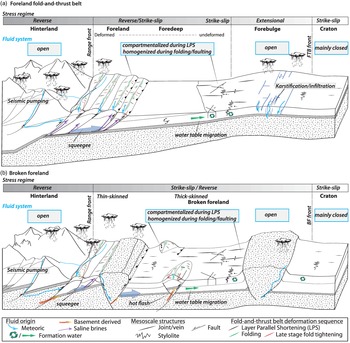
Orogenic forelands are regions where fluid migration intimately entwined with the development of deformational structures. In both fold-and-thrust belt – foreland basin systems (FTB hereinafter) or broken forelands (BF hereinafter), fluid migrations occur at the large scale (in relation with e.g. major faults) and at the mesoscale (in relation with e.g. mesoscale faults, joints, bands and stylolites (Figs 1, 2; Roure et al. Reference Roure, Swennen, Schneider, Faure, Ferket, Guilhaumou, Osadetz, Robion and Vandeginste2005; Groshong et al. Reference Groshong, Kronenberg, Couzens-Schultz and Newman2014; Lacombe et al. Reference Lacombe, Swennen and Caracausi2014; Agosta et al. Reference Agosta, Luetkemeyer, Lamarche, Crider and Lacombe2016; Lacombe & Rolland, Reference Lacombe and Rolland2016). The mesoscale structures directly affect the fluid transport by altering the porosity, either enhancing its connectivity with, for instance, fracturing, or reducing it with, for instance, cataclasis, consequently changing the permeability of a given rock volume. In turn, fluids interact with the rock to enhance the porosity locally by dissolution (e.g. Szymczak & Ladd, Reference Szymczak and Ladd2014) or to reduce it locally by either mineral precipitation (e.g. Bons et al. Reference Bons, Elburg and Gomez-Rivas2012) or mass transfer by pressure solution (e.g. Toussaint et al. Reference Toussaint, Aharonov, Koehn, Gratier, Ebner, Baud, Rolland and Renard2018). Studies of the interplays between fluid flow and deformation processes are numerous (e.g. Mourgues & Cobbold, Reference Mourgues and Cobbold2003; Laubach et al. Reference Laubach, Eichhubl, Hilgers and Lander2010, Reference Laubach, Lander, Criscenti, Anovitz, Urai, Pollyea, Hooker, Narr, Evans, Kerisit, Olson, Dewers, Fisher, Bodnar, Evans, Dove, Bonnell, Marder and Pyrak-Nolte2019; Cobbold et al. Reference Cobbold, Zanella, Rodrigues and Løseth2013; Dielforder et al. Reference Dielforder, Vollstaedt, Vennemann, Berger and Herwegh2015). Besides the reconstruction of the diagenetic evolution of rocks, a large literature has been dedicated to the reconstruction of past fluid flow associated to deformation by studying syn-kinematic mineralization associated to the development of large-scale fault zones (e.g. Lacroix et al. Reference Lacroix, Trave, Buatier, Labaume, Vennemann and Dubois2014; de Graaf et al. Reference de Graaf, Nooitgedacht, Goff, van der Lubbe, Vonhof and Reijmer2019; Smeraglia et al. Reference Smeraglia, Fabbri, Choulet, Buatier, Boulvais, Bernasconi and Castorina2019), deformation bands (Parry et al. Reference Parry, Chan and Beitler2004; Fossen et al. Reference Fossen, Schultz, Shipton and Mair2007; Zuluaga et al. Reference Zuluaga, Rotevatn, Keilegavlen and Fossen2016; del Sole et al. Reference del Sole, Antonellini, Soliva, Ballas, Balsamo and Viola2020), and vein networks at the scale of the fold and at the scale of the entire FTB/BF (e.g. Ferket et al. Reference Ferket, Roure, Swennen and Ortuño2000; Roure et al. Reference Roure, Swennen, Schneider, Faure, Ferket, Guilhaumou, Osadetz, Robion and Vandeginste2005; Sibson, Reference Sibson2005; Fischer et al. Reference Fischer, Higuera-Díaz, Evans, Perry and Lefticariu2009; Beaudoin et al. Reference Beaudoin, Bellahsen, Lacombe and Emmanuel2011, Reference Beaudoin, Bellahsen, Lacombe, Emmanuel and Pironon2014 a, Reference Beaudoin, Huyghe, Bellahsen, Lacombe, Emmanuel, Mouthereau and Ouanhnon2015; Fitz-Diaz et al. Reference Fitz-Diaz, Hudleston, Siebenaller, Kirschner, Camprubí, Tolson and Puig2011 a; Evans & Fischer, Reference Evans and Fischer2012; Crognier et al. Reference Crognier, Hoareau, Aubourg, Dubois, Lacroix, Branellec, Callot and Vennemann2018; de Graaf et al. Reference de Graaf, Nooitgedacht, Goff, van der Lubbe, Vonhof and Reijmer2019; Dielforder et al. Reference Dielforder, Villa, Berger and Herwegh2022).
Sketches representing a fold-and-thrust belt – foreland basin system (a) and a broken foreland (b). Stress regime, fluid system, source of fluids and engine of migrations, and mesoscale structures related to the folding event, from layer-parallel shortening to late stage of fold tightening, are reported.

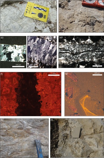
Field and microscope photographs of mesoscale structures studied for past fluid system reconstruction. (a, b) Veins in a fracture network in the Apennines, Italy (a) and in the Laramide province, USA (b). (c, d) Examples of vein textures: blocky calcite from the Apennines, Italy (c); elongated blocky calcite from southern Pyrenees, Spain (d). (e) Multiple fluid flow events and related cement precipitation in a crack seal, Laramide province, USA. (f, g) Cathodoluminescence images of a single phase of cementation in a vein whose borders were affected by dolomitization, Laramide province, USA (f), and of multiple diagenetic phases affecting a vein, Southeast Basin, France (g). Note pressure-solution (stylolite) along the vein border in (g). (h, i) Striated calcite steps along a fault surface, Laramide province USA (h), and fault breccia, associated to local overpressure, Jaca Basin, Spain (i).

This approach implies the reconstruction of the past fluid system (Evans & Fischer, Reference Evans and Fischer2012) from studying the syn-kinematic cement properties. The fluid system is characterized by (1) the nature of the fluid (i.e. formational, meteoric, basement-derived) from which the cement precipitated, (2) the temperature of precipitation (hotter or cooler than, or at equilibrium with, the surrounding rock), (3) the pressure regime at which the cement precipitated (under hydrostatic to sub-lithostatic), (4) the amount of interaction the fluid phase had with the host rock, and (5) the timing of the cement precipitation with consideration as to whether this age may also be the age of deformation, and (6) the hydraulic structure of the reservoir rock. A reservoir can be closed, i.e. with no lateral or vertical migration of fluids; it can be open and compartmentalized with stratified lateral migrations (i.e. no fluid external to the reservoir is involved), or with vertical migration limited by tectonic barriers like faults; finally it can be open and homogenized (i.e. with drains connecting it to other reservoirs or to the surface). One of the prime means of access to the past fluid system lies in the study of cements associated to the sequence of deformation that affected a given rock. Mineral precipitation in major fault zones, along mesoscale fault planes, in veins, and to a lesser extent associated to stylolite development, is the main and most studied marker of past fluids (Fig. 2). In this review, we focus on the mesoscale structures including fractures (faults, veins), bands and stylolite-related veins (e.g. tension gashes, reopened stylolites). For the sake of simplicity, we refer to all these mesoscale structures as the fracture network, as (1) all these develop following patterns (i.e. repetitive distribution) that arrange together as networks (Tavani et al. Reference Tavani, Storti, Lacombe, Corradetti, Muñoz and Mazzoli2015) and (2) they all are host to past fluid-derived mineralization related to deformation. The fracture network comprises sets of structures that can develop either locally (e.g. curvature at the fold hinge) or regionally (e.g. far field contraction). The cement that can fill a mesoscale structure can thus provide a good picture of the past fluid system at the time the structure developed, providing the cement is indeed coeval with the structure development, and that its chemistry remained unaltered. In mesostructures developed in FTB and BF, quartz and calcite are the most common minerals encountered. In this review, we will focus on syn-kinematic calcite cement, because it is the most frequently encountered in orogenic forelands as a majority of deformed rocks are carbonates in type. Calcite also yields more information about the past fluid system, even when considering only carbonate host rock. Calcite veins, striated calcite steps or calcite slickenfibres on mesoscale fault surfaces, and calcite veins around stylolites are ubiquitous in deformed sedimentary rocks in FTB/BF. Understanding the evolution of the past fluid system from calcite cements is bound to both the evolution of concepts and the continuous development of geochemical tools applied to calcite cements. Studying the syn-kinematic calcite cement geochemistry, some, if not all, of the parameters that constitute the fluid system can be understood for a given reservoir, providing a picture of the conduits used by the fluids during their migration, the so-called plumbing system. It also hints at the processes required to trigger and maintain the flow on a larger scale than the studied reservoir (Bjørlykke, Reference Bjørlykke and Farrell1994; Andresen, Reference Andresen2012). For instance, deciphering the past fluid system in FTB such as the Canadian Rocky Mountains has helped identify the main drains (faults/sedimentary interfaces) for hydrocarbon-rich fluids and the relative timing of the fluid migration along with the topographic-driven migration engine (Roure et al. Reference Roure, Andriessen, Callot, Faure, Ferket, Gonzales, Guilhaumou, Lacombe, Malandain, Sassi, Schneider, Swennen, Vilasi, Goffey, Craig, Needham and Scott2010). This kind of information provides boundary conditions to basin-scale fluid flow simulations that predict the migration pathways and rates, and ultimately the distribution of plays (Roure et al. Reference Roure, Swennen, Schneider, Faure, Ferket, Guilhaumou, Osadetz, Robion and Vandeginste2005, Reference Roure, Andriessen, Callot, Faure, Ferket, Gonzales, Guilhaumou, Lacombe, Malandain, Sassi, Schneider, Swennen, Vilasi, Goffey, Craig, Needham and Scott2010; Callot et al. Reference Callot, Sassi, Roure, Hill, Wilson and Divies2017).
This review aims at defining the concept of geochemistry-assisted structural geology, by focusing on the various case studies that report syn-kinematic calcite cement geochemical analysis in carbonate host rocks. We wish to illustrate what geochemical analysis can be conducted on syn-kinematic calcite cements to reconstruct the fluid temperature and pressure at the time of precipitation, the fluid origin, the age of precipitation, or the migration pathways. In turn, we question how this information can be used to qualitatively infer the distribution and activation time of the conduits, leading to deciphering structural information such as extension of faults, the nature of decoupling level, and the timescale of deformation. Hereinafter, we provide an overview of the geochemical techniques that can be used to characterize the conditions of precipitation of calcite cements (and to a lesser extent, quartz), and the chemistry of the fluid it precipitated from. Among others, we present classical techniques such as δ18O, δ13C, 87Sr/86Sr, elementary content, and fluid inclusion microthermometry, along with others under development such as Δ47CO2 and U–Pb geochronology. The prerequisite to a proper geochemical investigation of past fluid systems, i.e. a petrologic and diagenetic characterization of samples, will be briefly introduced, including vein petrography and techniques such as cathodoluminescence. We then present detailed examples of how the past fluid system can be reconstructed from calcite cements precipitated in major faults and/or in fracture networks at the scale of individual folds and at the scale of FTB (Canadian Rockies, Central Apennines, southern Pyrenees) or at the scale of the BF (Laramide province). More cases are then summarized, based on the large-scale structural style, in order to draw a complete picture of the relationship between the past fluid system, its evolution during deformation, and the structural geology of the subsurface.
Beyond the study of syn-kinematic cements in fault rocks from major faults, this review reports numerous studies focusing on the mesoscale structures (comprising faults and veins, but extended to stylolites and bands). Studying the fracture network in strata potentially allows access to the past fluids during a deformation history, from the weak deformation related to foreland flexure to the involvement of the strata in folds and/or thrusts as the FTB/BF developed (Fig. 1). This review excludes past fluid systems reconstructed from (1) magmatic fluids (e.g. MacDonald et al. Reference MacDonald, Faithfull, Roberts, Davies, Holdsworth, Newton, Williamson, Boyce and John2019) and related ore deposits (e.g. Jin et al. Reference Jin, Zhao, Feng, Hofstra, Deng, Zhao and Li2021), (2) hydrocarbon-dedicated geochemical techniques, and (3) geochemical techniques dedicated to non-carbonate veins, e.g. sulphur in gypsum cement (Machel, Reference Machel1985 b; Moragas et al. Reference Moragas, Martínez, Baqués, Playà, Travé, Alías and Cantarero2013). This review also does not examine how the understanding of a past fluid system can refine fluid flow simulation. As such, this contribution is to be seen as a complement to recent reviews dedicated to (1) how FTBs accommodate deformation through the development of mesostructures that damage reservoirs (Tavani et al. Reference Tavani, Storti, Lacombe, Corradetti, Muñoz and Mazzoli2015); (2) the specific relationship between fault zones and permeability (Faulkner et al. Reference Faulkner, Jackson, Lunn, Schlische, Shipton, Wibberley and Withjack2010) and more generally fault zone hydrogeology (Bense et al. Reference Bense, Gleeson, Loveless, Bour and Scibek2013); (3) the interplay between deformation and fluid flow at the fold scale (Evans & Fischer, Reference Evans and Fischer2012); (4) the prediction of past fluid flow in FTBs (Roure et al. Reference Roure, Swennen, Schneider, Faure, Ferket, Guilhaumou, Osadetz, Robion and Vandeginste2005, Reference Roure, Andriessen, Callot, Faure, Ferket, Gonzales, Guilhaumou, Lacombe, Malandain, Sassi, Schneider, Swennen, Vilasi, Goffey, Craig, Needham and Scott2010); (5) the petrophysical evolution of carbonates (Archie, Reference Archie1952; Regnet et al. Reference Regnet, David, Robion and Menéndez2019); and (6) the interplay between chemistry and deformation in carbonates (Laubach et al. Reference Laubach, Lander, Criscenti, Anovitz, Urai, Pollyea, Hooker, Narr, Evans, Kerisit, Olson, Dewers, Fisher, Bodnar, Evans, Dove, Bonnell, Marder and Pyrak-Nolte2019).
2. Fault zones and fracture networks: witnesses of past fluid flow
2.a. Development of fault zones and fracture networks
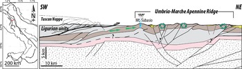
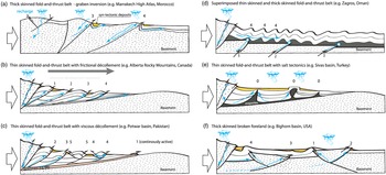
Orogenic forelands, that can be either fold-and-thrust belt – foreland basin systems or broken forelands, are the external parts of orogens where the deformation of sedimentary rocks occurred under diagenetic to low-grade metamorphic conditions of pressure and temperature, and in that sense are opposed to the higher-grade metamorphic hinterland (Fig. 1). The depth and degree of the mechanical decoupling level within the continental crust activated during collision has been widely debated for many years. One view states that the sedimentary cover is detached from the underlying basement along a shallow, low-strength décollement and deformed by thrusts with ramp-flat geometries rooting into the décollement level (thin-skinned tectonic style). This thin-skinned tectonic style supposes large-scale displacements and duplication of the sedimentary sequence, the underlying basement remaining undeformed (Lacombe & Bellahsen, Reference Lacombe and Bellahsen2016; Pfiffner, Reference Pfiffner2017). The low-strength décollement where thrusts are rooting at depth can be either viscous (e.g. salt, as in the Potwar Basin, Pakistan) or frictional (e.g. shales, as in the Alberta Rocky Mountains, Canada), or it can be associated with salt-related tectonic structures (e.g. the Sivas Basin, Turkey; Hudec & Jackson, Reference Hudec and Jackson2007; Callot et al. Reference Callot, Trocmé, Letouzey, Albouy, Jahani and Sherkati2012). The alternative view states that shortening involves a significant part of the crust along crustal-scale ramps above a deep ductile detachment (thick-skinned tectonic style). These are two end-members, and superimposed thin-skinned and basement-involved deformation may occur in various parts of the belt (Lacombe & Bellahsen, Reference Lacombe and Bellahsen2016; Pfiffner, Reference Pfiffner2017). Broken forelands (Fig. 1b) are characterized by basement uplifts, forming arches in a possibly erratic sequence of basement fault reactivation. These uplifts segment the former basin (Jordan & Allmendinger, Reference Jordan and Allmendinger1986; Horton et al. Reference Horton, Capaldi, Mackaman-Lofland, Perez, Bush, Fuentes and Constenius2022). Examples of broken forelands are the Laramide province in the western USA and the Sierras Pampeanas in Argentina.
The porosity and permeability of carbonate rocks are modified very early by diagenesis and later by structural damage. The latter develops mesoscale structures: (1) surfaces/bands that create porosity/permeability by fracturing, with a displacement either perpendicular to their surfaces (Fig. 2a–g; joints, veins and dilation bands) or along/oblique to their surfaces (Fig. 2h, i; faults and shear bands); and (2) surfaces/bands that reduce porosity/permeability by pressure-solution/cataclasis, with a motion either perpendicular to their surfaces (stylolites and compaction bands) or along/oblique to their surfaces (slickolites/shear bands). The distribution of these mesoscale structures varies spatially and temporally according to the position of the considered strata in the FTB/BF (Fig. 1). Considering carbonates, the formation of the fracture network starts during burial with the development of along-strike and across-strike joints and veins and of bedding-parallel sedimentary stylolites, the latter potentially developing at very shallow depths (<400 m; Toussaint et al. Reference Toussaint, Aharonov, Koehn, Gratier, Ebner, Baud, Rolland and Renard2018). During foreland flexure, along-strike and across-strike joints and veins oriented at high angle to bedding develop, along with normal faults, in the sedimentary series. These structures form in response to forebulge development and along-foredeep stretching (in blue in Fig. 1a). The folding event (Lacombe et al. Reference Lacombe, Beaudoin, Hoareau, Labeur, Pecheyran and Callot2021) starts with the layer-parallel shortening (LPS). LPS produces a network of structures comprising (1) joints and veins either at high angle to bedding and striking parallel to the shortening direction or parallel to bedding, (2) pressure solution cleavages, including tectonic stylolites, of which planes are oriented at high angle to bedding and perpendicular to the shortening direction, and (3) conjugate strike-slip or reverse faults. The LPS may still affect strata at the onset of fold growth (Fig. 3) up to c. 30° of bed tilting (Tavani et al. Reference Tavani, Storti, Lacombe, Corradetti, Muñoz and Mazzoli2015), and it can also develop bedding-parallel veins. In the orogenic foreland, fold growth is accommodated by flexural slip in the fold limbs and tangential longitudinal strain (e.g. outer-arc extension) at the fold hinge, the latter giving birth to along-strike joints at high angle to bedding as well as normal faults (Figs 1, 3). The fold ‘locks’ when limb rotation and/or kink-band migration cannot accommodate shortening anymore. At that stage, strata tilting is over but continuous horizontal shortening leads to late-stage fold tightening (LSFT), accommodated by mesoscale structures developing irrespective of bedding dip, such as (1) vertical conjugate strike-slip faults, (2) vertical joints striking parallel to the LPS-related ones, and (3) vertical tectonic stylolites oriented perpendicular to the shortening direction. At all stages of fold growth, earlier-formed fractures, either inherited from an ancient contractional event or from the foreland flexure preceding folding and thrusting, may also be reactivated (Guiton et al. Reference Guiton, Leroy and Sassi2003; Bergbauer & Pollard, Reference Bergbauer and Pollard2004; Bellahsen et al. Reference Bellahsen, Fiore and Pollard2006 b; Callot et al. Reference Callot, Robion, Sassi, Guiton, Faure, Daniel, Mengus and Schmitz2010 a; Sassi et al. Reference Sassi, Guiton, Leroy, Daniel and Callot2012). The folding event, encompassing deformation from the LPS to the LSFT, spans from a few Myr to a few tenths of Myr, according to the structural style and to the distance between the front of the range and the location of the (future) fold (Lacombe et al. Reference Lacombe, Beaudoin, Hoareau, Labeur, Pecheyran and Callot2021). It is important to note that in some specific cases this sequence will see development of fractures geometrically identical at various times of the deformation history, such as outer-arc extension related to the forebulge and to fold growth, or fold-axis perpendicular, LSFT and LPS fractures in fold limbs. In such cases, the origin of the fracture can only be assessed by robust relative chronology observations and/or might be assessed by geochemical, temperature and absolute age constraints on the filling cements precipitated during deformation.
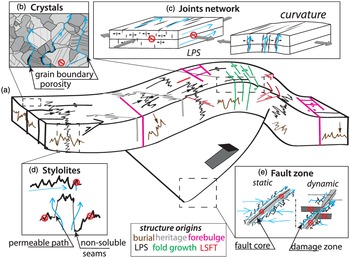
(a) Expected distribution of the mesoscale fracture pattern at the fold scale, including faults, joints and stylolites. Colours show the relation between the feature and the stage of deformation: brown relates to burial, grey to pre-orogenic, pink to outer arc extension during flexure, black to the layer-parallel shortening, green to fold growth, red to late stage of fold tightening. (b–e) Zoom on the expected fluid flow in the structures depicted in (a): (b) matrix-scale reactive fluid migration pathways; (c) migration pathways in joint network; (d) migration pathways in stylolites; (e) migration pathways in fault zones and cores, with the static state and the dynamic state. See text for details and references.

2.b. Fluid sources and fluid evolution during migration
FTB/BF develop with various structural styles, that affect (1) the availability of different fluid sources and (2) the triggers for the fluid migration (Fig. 1). Excluding magmatic fluids we can distinguish between various parent fluids at the time of precipitation: (1) surficial fluids such as meteoric fluids and formational water (seawater or fresh water); (2) crustal fluids, either described as basement fluids or as metamorphic fluids. The metamorphic fluids are either produced during retrograde metasomatic reactions (Yardley & Graham, Reference Yardley and Graham2002) or during prograde dehydration reactions (e.g. Hollocher, Reference Hollocher1991) occurring deeper in the crust. The fluids flowing in the basement rocks, beyond magmatic fluids, are proven to be usually derived from surficial fluids (Yardley & Graham, Reference Yardley and Graham2002). Similarly, formational water can evolve during fluid migration by interacting with the host rock in the basin, making so-called brines (or basinal fluids) if interacting with host rocks.
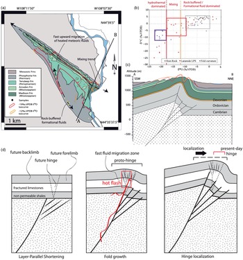
The fluid migration is triggered by various mechanisms (Fig. 1). The most common is the water table migration, or topographically driven flow, based on topographic/burial difference of a given stratum, that triggers pressure gradients making fluids migrate from the deepest towards the shallowest/highest part of the strata (Bjørlykke, Reference Bjørlykke and Farrell1994, Reference Bjørlykke2015), usually along the slope between the hinterland and the forebulge, or between synclines and anticlines. Migration can also be triggered by the stress gradient of units thrusting over others, expelling the fluid forelandwards. This mechanism, called squeegee, channelizes fluids along permeable horizons (Oliver, Reference Oliver1986) where fluid can migrate at a speed of 10 km Myr−1 over several million years (Ge & Garven, Reference Ge and Garven1994), with pulses up to 100 km Myr−1 (Michael & Bachu, Reference Michael and Bachu2001). Local stress accumulation in fault zones may also trigger ‘hot flashes’, an along-plane fast upward migration of hot fluids (Fig. 1; Machel & Cavell, Reference Machel and Cavell1999). Fluids can also flow downwards in fault zones following pressure gradients between the sealed and the broken domains during the seismic cycle (fault valve behaviour: Henderson & McCaig, Reference Henderson and McCaig1996; Sibson, Reference Sibson2000), or by enhancing permeability in the fault zone by local overpressure (Ortiz et al. Reference Ortiz, Person, Mozley, Evans and Bilek2019). Local chemical gradients between fluids and rocks can also enhance fluid migration, typically by carbonate dissolution, developing wormholes due to the flow of meteoric water undersaturated with respect to carbonates (Szymczak & Ladd, Reference Szymczak and Ladd2009; Petrus & Szymczak, Reference Petrus and Szymczak2016). This mechanism is efficient at a very shallow crustal level (Fig. 1).
2.c. Fault zones and fluid migration
At the scale of fault zones, the link between tectonics and fluid dynamics has been extensively investigated. For instance, the hydrological behaviour of fault zones, first introduced by Caine et al. (Reference Caine, Evans and Forster1996), has received a lot of attention since, with a compelling review proposed by Faulkner et al. (Reference Faulkner, Jackson, Lunn, Schlische, Shipton, Wibberley and Withjack2010). When displacement exceeds 1 m (Micarelli et al. Reference Micarelli, Benedicto and Wibberley2006), a fault can be divided into two main zones characterized by very different hydraulic behaviours (Fig. 3): the fault core, usually clay-rich, is a non-permeable zone, acting as a transverse barrier to the fluid which is forced to flow along the fault plane. In the surrounding damage zone, fractures develop (Fig. 2i), progressively increasing the connected porosity (Bense et al. Reference Bense, Gleeson, Loveless, Bour and Scibek2013). However, fast cement precipitation after hydrofracturing can potentially reduce the permeability, leading to an overpressure–failure cycle bound to the seismic cycle (Sibson, Reference Sibson and Knipe1990; Vass et al. Reference Vass, Koehn, Toussaint, Ghani and Piazolo2014). Regardless of the stress regime under which the fault developed, the damage zone is observed as being the main drain for the fluid, being especially efficient for a flow parallel to the fault plane (Agosta, Reference Agosta2008; Baietto et al. Reference Bau and Möller2008; Sutherland et al. Reference Sutherland, Toy, Townend, Cox, Eccles, Faulkner, Prior, Norris, Mariani, Boulton, Carpenter, Menzies, Little, Hasting, De Pascale, Langridge, Scott, Reid Lindroos, Fleming and Kopf2012).
2.d. Fracture network and fluid migration
At the scale of the mesostructures, and leaving aside deformation bands that are rare in carbonates (Tondi et al. Reference Tondi, Antonellini, Aydin, Marchegiani and Cello2006), two kinds of mesostructures exert a strong control on the fluid migration (Fig. 3c, d): the fractures, either opened in mode I (referred to as joints: Oliver & Bons, Reference Oliver and Bons2001; Sachau et al. Reference Sachau, Bons and Gomez-Rivas2015; Wennberg et al. Reference Wennberg, Casini, Jonoud and Peacock2016) or shear/hybrid in type (mode II or I + II), and the stylolites (Braithwaite, Reference Braithwaite1989). Regardless of the nature of the rock volume, the hydraulic efficiency of fractures is directly controlled by (1) the fracture aperture, (2) the orientation of the fracture plane with respect to the ambient stress field, (3) its vertical/lateral extent and (4) the density and connectivity of the fracture network. In carbonates, fracture density and permeability are linked to the diagenetic state of the reservoir and to the mechanical properties of the rock, namely stiffness and tensile strength. There are reciprocal controls between the diagenetic state of the rock and the fracture development, leading to the concept of mechanical stratigraphy (Ortega et al. Reference Ortega, Gale and Marrett2010; Barbier et al. Reference Barbier, Leprêtre, Callot, Gasparrini, Daniel, Hamon, Lacombe and Floquet2012 a; Wennberg et al. Reference Wennberg, Casini, Jonoud and Peacock2016). An efficient vertical fluid flow is observed in various folds (Evans & Fischer, Reference Evans and Fischer2012), probably related to an enhanced vertical extension of the joint network during folding. In contrast, joints developed during the LPS allowed efficient stratified, lateral migration of fluids with no vertical mixing in various case studies (Beaudoin et al. Reference Beaudoin, Bellahsen, Lacombe, Emmanuel and Pironon2014a, Reference Beaudoin, Labeur, Lacombe, Koehn, Billi, Hoareau, Boyce, John, Marchegiano, Roberts, Millar, Claverie, Pecheyran and Callot2020 c). These observations of different hydraulic behaviour for the same kind of joints led to the proposition that this difference is not due just to the different geometry, but probably also to the stress regime active, influencing fracture aperture (and its evolution during time) (Fig. 3). Indeed, joint networks developed during LPS under a strike-slip stress regime favour lateral fluid flow and fluid system stratification while joint networks developed in response to strata curvature under a local extensional stress regime favour vertical fluid flow and fluid homogenization between reservoirs. Although less efficient for fluid flow than fault zones, the mesoscale structures are also an important part of the palaeohydrology at the scale of the FTB (Beaudoin et al. Reference Beaudoin, Lacombe, Bellahsen and Emmanuel2013), and the veins can reliably be used to reconstruct the fluid system related to both large-scale and local tectonics.
The role of stylolites on the fluid system remains vastly overlooked in that context, except to constrain the diagenesis related to the burial phase or the early LPS (Swennen et al. Reference Swennen, Muskha and Roure2000; Roure et al. Reference Roure, Andriessen, Callot, Faure, Ferket, Gonzales, Guilhaumou, Lacombe, Malandain, Sassi, Schneider, Swennen, Vilasi, Goffey, Craig, Needham and Scott2010; Vandeginste et al. Reference Vandeginste, Swennen, Allaeys, Ellam, Osadetz and Roure2012). Stylolites are mainly considered as efficient barriers for fluid flow, since they accumulate non-soluble, non-permeable material along their dissolution plane, and redistribute cement around, clogging the porosity (Nelson, Reference Nelson1981). This consideration makes stylolites interpreted as structures able to compartmentalize a reservoir (Roure et al. Reference Roure, Andriessen, Callot, Faure, Ferket, Gonzales, Guilhaumou, Lacombe, Malandain, Sassi, Schneider, Swennen, Vilasi, Goffey, Craig, Needham and Scott2010). Yet, a growing number of natural observations and experimental case studies reveal that stylolites can be efficient drains for fluid flow (Koehn et al. Reference Koehn, Rood, Beaudoin, Chung, Bons and Gomez-Rivas2016; Heap et al. Reference Heap, Reuschlé, Baud, Renard and Iezzi2018; Martín-Martín et al. Reference Martín-Martín, Gomez-Rivas, Gómez-Gras, Travé, Ameneiro, Koehn and Bons2018; Toussaint et al. Reference Toussaint, Aharonov, Koehn, Gratier, Ebner, Baud, Rolland and Renard2018; Bruna et al. Reference Bruna, Lavenu, Matonti and Bertotti2019). The impact of stylolites on the fluid flow depends on the orientation of the stylolite with respect to the flow, i.e. guiding a fluid flow parallel to the dissolution plane, and blocking the flow perpendicular to the dissolution plane (Fig. 3). This behaviour, similar to that of a fault zone, was observed in nature with a channelization of the reactive fluid flow along a stylolite plane (Martín-Martín et al. Reference Martín-Martín, Gomez-Rivas, Gómez-Gras, Travé, Ameneiro, Koehn and Bons2018; Humphrey et al. Reference Humphrey, Gomez-Rivas, Koehn, Bons, Neilson, Martín-Martín and Schoenherr2019) and in experiments (Heap et al. Reference Heap, Reuschlé, Baud, Renard and Iezzi2018). Yet it is not the only controlling factor of permeability to fluid flow. Indeed, Koehn et al. (Reference Koehn, Rood, Beaudoin, Chung, Bons and Gomez-Rivas2016) have observed ore-bearing stylolites in the Zechstein carbonate units (Germany), which demonstrates a strong control of the stylolite morphology over the fluid flow. They proposed a new classification in which the morphology of the stylolite, i.e. rectangular, suture and sharp peak, seismogram and simple wave-like, itself controlled by the growth rate of the stylolite, controls its impact over the fluid flow. In the classification, the stylolites that have high-amplitude peaks undergo a growth that locally shifts the non-permeable residue layer, allowing a fluid flow across the stylolite plane. It is important to note that because of local stress perturbations (Aharonov & Karcz, Reference Aharonov and Karcz2019), cracks can open during pressure solution and be filled with cement that will record information in relation to the stylolite development. Considering the complexity of stylolite development and its potential impact on fluid flow, it appears necessary to further investigate stylolites and reappraise their role in past fluid systems.
Though beyond the scope of this review, it is worth mentioning that the fluid chemistry may itself impact fluid flow, for instance through dissolution or fluid-mediated replacement, that will affect the fluid dynamics down to the crystal scale. Classic examples of the latter in carbonates are dolomitization or apatitization processes, and recent experimental works (Jonas et al. Reference Jonas, John, King, Geisler and Putnis2014; Pedrosa et al. Reference Pedrosa, Boeck, Putnis and Putnis2017; Weber et al. Reference Weber, Cheshire, Bleuel, Mildner, Chang, Ievlev, Littrell, Ilavsky, Stack and Anovitz2021) and natural observations (Centrella et al. Reference Centrella, Beaudoin, Derluyn, Motte, Hoareau, Lanari, Piccoli, Pecheyran and Callot2021) highlighted the prominent role of grain boundaries and mineralogical defects like cleavage planes on the fluid flow at that scale (Fig. 3).
2.e. Past fluid flow markers
Reconstructing fluid flow in orogenic forelands requires identification of markers of past fluid flow. These witnesses can be indirect, like the contrasted colour halo in the host rock around a fracture related to the migration of a fluid with a different redox state than the host (e.g. Eichhubl et al. Reference Eichhubl, Taylor, Pollard and Aydin2004; Stel, Reference Stel2009; Missenard et al. Reference Missenard, Bertrand, Vergely, Benedicto, Cushing and Rocher2014). In such cases, quantitative information remains very limited. More interestingly, there is a wealth of direct markers of past fluid flow, like cements precipitating in breccia during hydrofracturing (Fig. 2i), even though the link between breccia texture and hydrofracturing is nowadays questioned (Centrella et al. Reference Centrella, Beaudoin, Koehn, Motte, Hoareau and Callot2022). Mineralogical phase transformation such as dolomitization is another example of a well-studied marker that allows reconstruction of the past fluid system (e.g. Martín-Martín et al. Reference Martín-Martín, Gomez-Rivas, Bover-Arnal, Travé, Salas, Moreno-Bedmar, Tomás, Corbella, Teixell, Vergés and Stafford2013; Koeshidayatullah et al. Reference Koeshidayatullah, Corlett, Stacey, Swart, Boyce, Robertson, Whitaker and Hollis2020 a, b; Centrella et al. Reference Centrella, Beaudoin, Derluyn, Motte, Hoareau, Lanari, Piccoli, Pecheyran and Callot2021; Motte et al. Reference Motte, Hoareau, Callot, Revillon, Piccoli, Calassou and Gaucher2021). Yet, the most studied witness of the past fluid flow in contractional settings consists in the cements filling fractures (veins and faults), including the fluid inclusions they host (Bons et al. Reference Bons, Elburg and Gomez-Rivas2012; Laubach et al. Reference Laubach, Lander, Criscenti, Anovitz, Urai, Pollyea, Hooker, Narr, Evans, Kerisit, Olson, Dewers, Fisher, Bodnar, Evans, Dove, Bonnell, Marder and Pyrak-Nolte2019). In FTB and BF, the mineralogy of such filling, beyond calcite and quartz, can include fluorite, ores or gypsum.
3. Bounding cement precipitation from past fluid to deformation: the role of petrography
In order to reconstruct the past fluid properties during deformation, it is important to (1) unambiguously link cement precipitation to the timing of development of the studied structure (fault, vein, stylolite), and (2) check whether the cement has been altered or not by later diagenetic events. This is a prerequisite to any robust geochemical analysis of the past fluid system. In the case of cements associated to faults, the observation of either cement in cataclasites (Fig. 2i) or, better, of striated calcite steps (Fig. 2h) is a reliable way to ensure that the cement precipitated from a fluid involved during the deformation, provided the breccia cement is not a simple matter of recrystallization (Centrella et al. Reference Centrella, Beaudoin, Koehn, Motte, Hoareau and Callot2022). In the case of veins, a robust petrographic study is systematically required prior to any geochemical analysis being performed. First, the nature of the filling is an obvious yet ambiguous indicator of the nature of the fluid. For example, the occurrence of gypsum veins indicates the involvement of fluids that were in contact with evaporitic layers in the reservoir (Pichat et al. Reference Pichat, Hoareau, Callot, Legeay, Kavak, Révillon, Parat and Ringenbach2018), but it cannot argue in favour of the evaporites being the source of the fluids (dehydration during the tectonic remobilization of a salt layer) or part of the migration pathway of the fluid (a meteoric fluid percolating within a gypsum level; e.g. Travé et al. Reference Travé, Labaume and Vergés2007). Another example is the content of the crystal fluid inclusions (halite crystals, hydrocarbons) that can also be informative about either the fluid origin or its pathways. In their review, Bons et al. (Reference Bons, Elburg and Gomez-Rivas2012) illustrate what vein cement texture can tell us about the mode of deformation, and about the common timing between vein opening and cement precipitation (Fig. 2c–e). The coevality between precipitation of cement and deformation is obvious when the cement precipitates as fibrous crystals in opened veins (Bons et al. Reference Bons, Elburg and Gomez-Rivas2012), or when the vein growth is driven by crystallization forces during precipitation (Gratier et al. Reference Gratier, Frery, Deschamps, Røyne, Renard, Dysthe, Ellouz-Zimmerman and Hamelin2012; Cobbold et al. Reference Cobbold, Zanella, Rodrigues and Løseth2013). In the case of a syntaxial texture supporting the growth-induced opening of a vein (Fig. 2d), experimental data suggest that a very high fluid flow is required to keep the crystal growth rate sufficiently high (Lee & Morse, Reference Lee and Morse1999; Hilgers & Urai, Reference Hilgers and Urai2002 b). In the case where the timing of precipitation is ambiguous with respect to the development of the fracture (e.g. in presence of blocky calcite; Fig. 2c), the process that triggered precipitation must be questioned. In the case of calcite, a mineral with a retrograde solubility (Segnit et al. Reference Segnit, Holland and Biscardi1962), oversaturation for a given fluid is reached when temperature increases or when pCO2 decreases. Precipitation can be triggered by mixing between hydrothermal migrating fluids and local fluids. In cases where fluid mixing is not supported by data, authors have considered that the opening of the fracture triggers the precipitation by locally reducing pCO2 (Beaudoin et al. Reference Beaudoin, Bellahsen, Lacombe, Emmanuel and Pironon2014 a; Cruset et al. Reference Cruset, Cantarero, Vergés, John, Muñoz-López and Travé2018). It is interesting to note that the recent study of Roberts and Holdsworth (Reference Roberts and Holdsworth2022) suggests that veins developed as crack seal are optimal to access the past fluid at the time of deformation, even though this needs to be considered with care as Bons et al. (Reference Bons, Elburg and Gomez-Rivas2012) clearly showed that a crack seal can be related to multiple events of deformation.
When a cement is considered to be linked to the fracture development, a second mandatory petrographic step is to check that the cement was not altered by diagenesis. Indeed, calcite crystals can keep their initial chemical signature pristine at low-grade metamorphism (e.g. Dielforder et al. Reference Dielforder, Villa, Berger and Herwegh2022), so it is important to discard the idea that dissolution/reprecipitation or recrystallization processes affected the cement. A classical tool used for that purpose is cathodoluminescence (Fig. 2f, g) ( Machel, Reference Machel1985 a; Reference Machel1997). The natural luminescence of calcite (but also of quartz, fluorite, gypsum) in a vein is informative about (1) the number of cement phases in the fracture, and/or alteration events affecting the vein cements, (2) the redox state of the fluid, itself arguably relatable to the fluid origin (Machel, Reference Machel1997), and (3) the rate of precipitation of calcite cement, variation of which can create luminescence zoning (Dromgoole & Walter, Reference Dromgoole and Walter1990; Boggs & Krinsley, Reference Boggs and Krinsley2006). For the latter, the relative part of the growth rate with regard to the surface growth preference has been debated (Reeder & Grams, Reference Reeder and Grams1987). Above all, ensuring that the cement filling the vein precipitated in a single phase (homogeneous luminescence; Fig. 2f), and that it has not been subsequently altered (Fig. 2g) is key to validate that the geochemical analysis of the cement actually yields information about the past fluid (e.g. van Geet et al. Reference van Geet, Swennen, Durmishi, Roure and Muchez2002; Hanks et al. Reference Hanks, Parris and Wallace2006; Barbier et al., Reference Barbier, Leprêtre, Callot, Gasparrini, Daniel, Hamon, Lacombe and Floquet2012 a). That preliminary step is mandatory to allow further interpretation of a geochemical dataset with respect to the tectonic history of an area.
4. Geochemical proxies to reconstruct the past fluid system
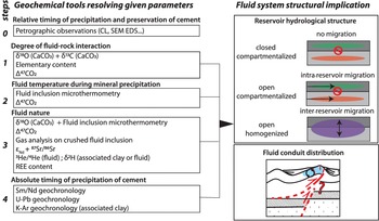
In this section we review the basic concepts and pitfalls of the geochemical techniques that are used for, but not limited to, the reconstruction of part of the past fluid system when applied to calcite cement in tectonic structures. We first focus on the most classical techniques, then summarize the less developed/applied ones. Figure 4 presents an ideal workflow of how these techniques can be applied to a sample, with emphasis on what (combination of) analysis can be used to access specific parameters of the fluid system. For reviews of the use of geochemistry for past fluid beyond its relation to tectonics (e.g. diagenesis), we refer the reader to the existing literature (Emery & Robinson, Reference Emery and Robinson1993; Swart, Reference Swart2015).
Concept of geochemistry-assisted structural geology. Left-hand side: representation of all parameters (bold) that can be reconstructed from geochemical analysis (framed) on calcite, organized in a suggested workflow. The suggestion is to pick at least one of the analyses of each box to reconstruct the past fluid system with the least ambiguity. Right-hand side: structural implication of the outcome of the past fluid system reconstruction, including a direct appraisal of the reservoir hydrological structure, and an inferred model of the fluid conduit distribution in time and space.

4.a. Fluid inclusions
Fluid inclusions are micrometre- to millimetre-scale inclusions – filled with fluids, or a combination of fluid, vapour and solid – that are ubiquitous in crystals (Goldstein & Reynolds, Reference Goldstein and Reynolds1994). Three types of fluid inclusions are classically described (Roedder, Reference Roedder1984; Goldstein & Reynolds, Reference Goldstein and Reynolds1994): (1) the primary fluid inclusions, that are defects related to the crystal growth itself. Primary fluid inclusions mainly occur along the crystal growth rims, and mostly have a shape corresponding to the crystal habitus. (2) Pseudo-secondary fluid inclusions are not directly distributed in a pattern linked to the crystal growth, yet they are lined onto deformation planes that developed during the crystal growth, being limited to the crystal. (3) Secondary fluid inclusions appear as trails, the orientation of which is not related to the crystal growth; they can be considered as post-growth mode I joints at the crystal scale (e.g. André et al. Reference André, Sausse and Lespinasse2001). Regardless of the type of inclusions, the mineralizing fluid is trapped at set pressure and temperature. Assuming that (1) the volume of the inclusion remains constant, (2) fluid–solid chemical exchanges are null and thus (3) the fluid chemistry is constant, the pressure and temperature decrease during the subsequent exhumation of the crystal triggers phase changes potentially leading to the development of a vapour bubble (e.g. Bourdet et al. Reference Bourdet, Pironon, Levresse and Tritlla2008). Fluid inclusions might be one-phase, two-phase with vapour/liquid or liquid/solid, or three-phase with coexistence in the laboratory conditions of solid, vapour and liquid phases, the former being typical of highly saline fluids (Goldstein & Reynolds, Reference Goldstein and Reynolds1994). In the following paragraphs, we do not mention techniques that rely on hydrocarbon-bearing fluid inclusions. For more information than is summarized hereinafter, please refer to the detailed technical review by Chi et al. (Reference Chi, Diamond, Lu, Lai and Chu2020).
The original analysis conducted with fluid inclusions consists in reconstructing the temperature and pressure condition of fluid entrapment, i.e. at the time the crystal precipitated, by means of microthermometry. A thick section of mineral is heated up under the microscope using a temperature-controlled microthermometric stage in order to measure the temperature at which the vapour phase becomes homogeneous with the liquid one. This is called the temperature of homogenization (T h), and corresponds to the minimal temperature of the fluids when it was trapped in the inclusion (Goldstein & Reynolds, Reference Goldstein and Reynolds1994). Note that if the fluid temperature is lower than 50 °C at the time of entrapment, the vapour bubble will usually be absent or may not be visible in laboratory conditions, but it can be nucleated or enlarged by freezing the fluid. With the knowledge of, or by assuming, the fluid chemical system and the pressure of entrapment (i.e. depth), one can reconstruct the absolute temperature of precipitation. By comparing it to the expected temperature at which the host rock was at the time of precipitation, by considering a geothermal gradient and a past depth, it is then possible to assess if the fluid is hydrothermal (hotter than the local temperature), geothermal (equal to the local temperature) or hydrofrigid (colder than the local temperature) sensu Machel and Lonnee (Reference Machel and Lonnee2002). Microthermometry is also used to estimate the type of salts and the salinity of the system. The protocol is to freeze the studied fluid inclusion, and to heat it back up slowly to measure (1) the temperature(s) at which the ice starts to melt (i.e. eutectic temperature(s) T e), which relates to the fluid composition (Davis et al. Reference Davis, Lowenstein and Spencer1990), and (2) the temperature at which the last cube of ice disappears, i.e. the ice melting temperature (Tm ice). In a simple H2O–NaCl system, the temperature at which a frozen fluid inclusion becomes completely liquid is directly related to the fluid salinity.
Two major pitfalls affect fluid inclusion microthermometry in calcite cement. The first is that the approach is valid only under the assumption that the volume and chemistry of the inclusion remained constant. In weak crystals such as calcite (Goldstein, Reference Goldstein1986; Bodnar, Reference Bodnar, Samson, Anderson and Marshall2003), volume might easily vary (1) during the analysis and (2) throughout the crystal history, especially in deformed areas. The variation in volume of the inclusion will usually have a petrographic effect on the shape of the inclusion (e.g. stretching), or a visible effect on the vapour bubble membrane, making it impossible to consider the measured T h in the dataset of measurements. In order to avoid misleading temperature data, the norm is to conduct a rigorous petrographic study to distinguish between the different generations of fluid inclusions in a given cement, then first to measure the homogenization temperature of fluid inclusion populations before the eutectic and ice melting temperatures (as freezing likely will stretch the inclusions), and then to use the modal value of population distribution as representative of the T h. When data is available, the comparison of the distribution with current geothermal temperature might also indicate a thermal re-equilibration of the fluid inclusion population with the current temperature, involving volume variations within the studied fluid inclusions (Bodnar, Reference Bodnar, Samson, Anderson and Marshall2003). The second pitfall is that, considering the usual size of inclusions in calcite (<10 µm), the eutectic and melting temperatures are usually very hard to constrain because of technical limitation related to their limited size.
Fluid inclusions can also grant direct access to the fluid composition. One method consists in evaporating the liquid phase following sample crushing (e.g. Blamey, Reference Blamey2012; Dassié et al. Reference Dassié, Genty, Noret, Mangenot, Massault, Lebas, Duhamel, Bonifacie, Gasparrini, Minster and Michelot2018) and analysing its elemental or isotopic composition by either mass spectrometry or gas chromatography. In spite of recent progress, allowing data to be obtained from down to 0.1 µL of fluid by crushing, the main limitation is related to the fact that it would be required to crush only primary/pseudo-secondary fluid inclusions, which appear to be complicated, even with a solid petrographic characterization. Böhlke and Irwin (Reference Böhlke and Irwin1992) showed that it was possible to analyse the fluid inclusions directly, but at the time it worked only for 10−11 L of fluid, in inclusions of very large dimensions (hundreds of µm). Laser absorption spectroscopy allows the reduction of these dimensions to a few tens of µm (Affolter et al. Reference Affolter, Fleitmann and Leuenberger2014). Yet future development in mass spectrometry on the one hand and in spotted sampling such as laser ablation on the other hand might lead to exciting developments enabling study of the content of selected fluid inclusion related to specific tectonic stages without crushing. A second method to access the fluid trapped in inclusions is to perform Raman spectroscopy on the fluid inclusion (Rosasco et al. Reference Rosasco, Roedder and Simmons1975). Raman spectroscopy is usually coupled to microthermometry to gradually heat up the inclusion during the measurement, and so to characterize and quantify the nature and amount of chemical components trapped in the fluid inclusion. This technique is mainly developed for oil-bearing fluid inclusions (e.g. Guillaume et al. Reference Guillaume, Teinturier, Dubessy and Pironon2003) and allows, when combined with other techniques, for proper computation of the chemical composition of the fluid inclusion, i.e. the isochore and isopleth curves (Bakker, Reference Bakker2003), or for direct determination of the salinity of aqueous fluid inclusions (Caumon et al. Reference Caumon, Dubessy, Robert and Tarantola2014). When aqueous fluid inclusion microthermometry is combined with coeval oil-bearing fluid inclusion microthermometry, it becomes possible to access the exact pressure and temperature of entrapment of the fluid (Pironon & Bourdet., Reference Pironon and Bourdet2008).
4.b. Established isotope-based techniques
4.b.1. Oxygen
Oxygen stable isotope measurements consist in measuring the ratio between the 18O and the 16O of the oxygen-bearing mineral (carbonates, but also quartz or clays), dividing it by the measured ratio between the 18O and 16O of a standard itself calibrated to a reference (Standard Mean Ocean Water (SMOW) for liquid phase, PeeDee Belemnite (PDB) for carbonates), as follows:
 $$ {{\rm{\delta }}^{18}}{\rm{O}} = \left( {{\raise0.7ex\hbox{${{{({}_{}^{18}{\rm{O}}/{}_{}^{16}{\rm{O}})}_{{\rm{sample}}}}}$} \!\mathord{\left/ {\vphantom {{{{({}_{}^{18}{\rm{O}}/{}_{}^{16}{\rm{O}})}_{{\rm{sample}}}}} {{{({}_{}^{18}{\rm{O}}/{}_{}^{16}{\rm{O}})}_{{\rm{standard}}}}}}}\right.\kern-0pt}\!\lower0.7ex\hbox{${{{({}_{}^{18}{\rm{O}}/{}_{}^{16}{\rm{O}})}_{{\rm{standard}}}}}$}} - 1} \right)*1000$$
The δ18O is expressed in per mil with respect to the reference (‰ PDB or ‰ SMOW). This technique can be performed using a few µg of pure carbonate (40 µg) obtained from machine-assisted sampling, or using laser or ionic ablation (Becker, Reference Becker2002). This ensures very easy data acquisition with minimal preparatory work, at very low cost and with relatively high precision (0.1−0.5 ‰ depending on the set-up used) (Swart et al. Reference Swart, Burns and Leder1991).
In the case of carbonates, studying oxygen isotopic ratio considers the exchange between the H2O content of the fluid and CaCO3. The formula that links the δ18O value of the carbonate to the δ18O of the water is as follows:
 $${{\rm{\delta }}^{18}}{{\rm{O}}_{{\rm{CaC}}{{\rm{O}}_3}}} = \;{{\rm{\delta }}^{18}}{{\rm{O}}_{{{\rm{H}}_2}{\rm{O}}}} + 1000\ln \alpha $$
The fractionation coefficient α is primarily controlled by the temperature at which the phase change occurs (precipitation or dissolution). Since the seminal work of Epstein et al. (Reference Epstein, Buchsbaum, Lowenstam and Urey1953) that used CaCO3 mineralized by gastropods to show a relationship between the δ18 CaCO3 and the temperature of the fluid, numerous experimental studies have established palaeothermometers valid for different temperatures (e.g. Craig, Reference Craig1957; Kim & O’Neil, Reference Kim and O’Neil1997; Zheng, Reference Zheng1999; Hu & Clayton, Reference Hu and Clayton2003; Chacko & Deines, Reference Chacko and Deines2008; Horita, Reference Horita2014). For instance, the most widely used equation might be that of Kim and O’Neil (Reference Kim and O’Neil1997):
 $$1000\ln {\alpha _{\left( {{\rm{CaC}}{{\rm{O}}_3} - {{\rm{H}}_2}{\rm{O}}} \right)}} = 18.03\left( {{{10}^{ - 3}}*{T^{ - 1}}} \right) - 32.42$$
where T is the phase transition temperature in kelvin. In other words, the δ18O value of the carbonate phase decreases as the temperature of precipitation increases. Even though the carbonate veins are mostly exclusively filled with calcite in orogenic forelands, it is worth noting that the equivalent relationships were also calibrated for the other carbonates (most used equations are gathered online by Beaudoin and Therrien, Reference Beaudoin and Therrien2004).
However, other physical and chemical processes affect the oxygen isotope fractionation in debated ways: the evaporation rate (Dreybrodt & Deininger, Reference Dreybrodt and Deininger2014) and the fluid composition and precipitation kinetics (Bottinga & Craig, Reference Bottinga and Craig1968; Rye & Bradbury, Reference Rye and Bradbury1988, Zeebe, Reference Zeebe2007). Most of these secondary factors seem negligible in a tectonic system where calcite precipitates in veins or in faults, yet the direct use of the δ18O value alone as a palaeothermometer is arguable. Indeed, both δ18OH2O and δ18OCaCO3 of the vein cement are required to access the temperature of precipitation of the cement at the time of deformation. The way around this is to assume the vein cement precipitated from a fluid that derives from the local fluids contained in the host rock. In that case, the value of δ18OH2O can be calculated using the measured δ18OCaCO3 in the host rock and a temperature of precipitation T assumed from the reconstruction of the surface temperature at the time the host rock precipitated. The value of T is then used in Eqn (3), the resulting value of 1000 ln α allowing for the calculation of the δ18OH2O using Eqn (2).
Assuming that the cement filling the fractures derives from the local fluid (seawater or freshwater) leads to the conjecture that a single fluid is involved in the system. That allowed many authors to explain an isotopic trend commonly observed in the fracture cements (Fig. 5). Indeed, the joint decrease of the δ18OCaCO3/δ13CCaCO3 values in vein cements related to burial and LPS is a recurring pattern (e.g. de Graaf et al. Reference de Graaf, Nooitgedacht, Goff, van der Lubbe, Vonhof and Reijmer2019), usually interpreted as a remobilization of local fluid during progressive burial, at increasing temperatures (Fig. 5a (Beaudoin et al. Reference Beaudoin, Bellahsen, Lacombe and Emmanuel2011), Fig. 5d (de Graaf et al. Reference de Graaf, Nooitgedacht, Goff, van der Lubbe, Vonhof and Reijmer2019)). Such interpretation needs to be supported by independent temperature constraints. In case a, homogenization temperatures obtained from fluid inclusion microthermometry support the idea that some of the cements characterized by δ18OCaCO3 >−15 ‰ PDB can be explained by cement precipitation from seawater during burial. Yet altogether the combination of T h and δ18OCaCO3 predicted that most of the cement had precipitated from a mixed fluid, highlighting extra-reservoir migrations. Cases b (Cruset et al. Reference Cruset, Cantarero, Travé, Vergés and John2016) and c (Curzi et al. Reference Curzi, Bernasconi, Billi, Boschi, Aldega, Franchini, Albert, Gerdes, Barberio and Carminati2021) in Fig. 5 considerably challenge this classical ‘burial’ interpretation. Indeed, independent temperatures of deformation-related cements obtained using clumped isotopes Δ47CO2 in both cases show that the cements exhibiting a more depleted δ18O precipitated at a significantly lower temperature (c. 30 °C) than the cements exhibiting a less depleted δ18O value. In that case, the isotopic pattern is interpreted as the precipitation from two different fluids (seawater and meteoric water) with no temperature effect relatable to burial or exhumation. These examples illustrate that an interpretation of a fluid system based solely on the classical δ18O–δ13C must be treated with care as it is easy to misinterpret the isotopic data. Following this line of argument, it is important not to use just the δ18O–δ13C of the vein and of the host rock to infer that the fluid is local or external to the reservoir. The isotopic equilibrium between the host rock and the vein cement is usually interpreted as due to rock buffering, i.e. a fluid/rock ratio strongly in favour of the rock, erasing the original fluid isotopic ratio. One needs to consider that with a fluid/rock ratio strongly in favour of the fluid, the isotopic ratio of the surrounding rock can be overprinted. Thus, it is important to couple with other techniques that will investigate the chemical equilibrium between the fluid and the host rock, such as elementary content.
Simplified representation of δ18O vs δ13C plots obtained in syn-kinematic calcite cements from the fracture network (a, b, d) and in thrust fault zone (c), along with interpretation of the related fluid system. The published interpretations are reported on each graph. (a) The Sheep Mountain Anticline past fluid system (modified after Beaudoin et al. Reference Beaudoin, Bellahsen, Lacombe and Emmanuel2011). (b) The Puig-Reig Anticline past fluid system (modified after Cruset et al. Reference Cruset, Cantarero, Travé, Vergés and John2016). (c) The Mount Tancia thrust fault zone past fluid system (modified after Curzi et al., Reference Curzi, Aldega, Bernasconi, Berra, Billi, Boschi, Franchini, van der Lelij, Viola and Carminati2020). (d) The past fluid system of the Albanide fold-and-thrust belt (modified after de Graaf et al. Reference de Graaf, Nooitgedacht, Goff, van der Lubbe, Vonhof and Reijmer2019). Note that the coloured frames in (a) locate the extension of plots (b–d). On all plots, the dashed grey frame represents the isotope values of the calcite fraction of the host rock when available. All values are given in ‰ PDB. T on plots refers to the measured temperatures of a given population, using an independent paleothermometer (T 47 for Δ47CO2, T h for fluid inclusion homogenization temperatures). LPS stands for layer-parallel shortening.

4.b.2. Carbon
Carbon stable isotope measurements in carbonate phases deal with the ratio between 13C and 12C, obtained with the same protocol as δ18O, and reported as ‰ PDB (see Eqn (1) for the formula, replacing O isotopes by C isotopes). In carbonates, the carbon is mainly provided by the dissolved carbonate species (HCO3−, CO32−) and so the δ13C values of host rock carbonate are mostly similar to δ13C values of dissolved inorganic carbon, with other minor control parameters such as kinetics, pH and temperature of precipitation (Bottinga, Reference Bottinga1969). Similarly, the δ13C value of carbonate cement is bounded to the δ13C value of the parent fluid. The latter can vary significantly, in particular under the influence of organic matter degradation due to bacterial activity (e.g. sulphate reduction or methanogenesis) or thermal degradation (Irwin et al. Reference Arndt, Virgo, Cox and Urai1977; Curtis, Reference Curtis, Brooks and Welte1987). δ13C values of carbonates allow diagnosis of the bacterial activity related to oil and gas formation. δ13Cfluid is positive in the case methanogenesis occurred, while δ13Cfluid is negative in case there is an influence of a deeper methane source (δ13Cfluid shows values down to −60 ‰ PDB). In the case there is oil production, the δ13Cfluid values go down as far as −35 ‰ PDB (Peckmann & Thiel, Reference Peckmann and Thiel2004). δ13Cfluid of the inorganic carbon in seawater is c. 0 ‰ PDB while it is c. −10 ‰ PDB in meteoric water. However, interpreting a δ13C value in a calcite cement requires consideration of the mixing trends between end-members, δ13C values of which are often assumed because seldom accessible to measurements. As such, it is impossible to distinguish between (1) a partial mixing between a calcite precipitated from 70 % of pristine marine seawater (0 ‰ PDB) and 30 % of a seawater where organic carbon has been altered (−30 ‰ PDB) (considering the abundances of carbon are identical in both seawaters, the mix would have a value of −9 ‰ PDB) and (2) a calcite precipitated from 100 % pristine meteoric water (−10 ‰ PDB). As for δ18O values, the interpretation of δ13C remains ambiguous when the fluid source is unknown (Fig. 5). On top of this, recent experimental work has proven that δ13C values of carbonates precipitated from the same fluid source, at the same temperature, could present a shift of c. 3 ‰, due to the precipitation rate only (Yan et al. Reference Yan, Dreybrodt, Bao, Peng, Wei, Ma, Mo, Sun and Liu2021). This parameter being elusive when studying tectonic structures, such study supports that δ13C values must be used as a proxy with a great deal of care.
4.b.3. Δ47CO2 palaeothermometry
The clumping of isotopes, i.e. the association of isotopes into specific mass ion groups, so-called isotopologues, has been studied for decades, yet it is only recently that the concept has been developed for unravelling carbonate precipitation temperature conditions. After methodological locks were lifted by Eiler and Schauble (Reference Eiler and Schauble2004), showing it is possible to measure CO2 isotopologues with good accuracy, Ghosh et al. (Reference Ghosh, Adkins, Affek, Balta, Guo, Schauble, Schrag and Eiler2006) developed a thermometer based on the thermodynamical equilibrium of the doubly substituted isotopologue 13C18O16O. As defined by the authors, the enrichment of 13C18O16O in CO2 measured during acid digestion of CaCO3 relative to stochastic distribution of isotopes among all isotopologues is temperature-dependent. This enrichment, called Δ47CO2, relies on the fact the heavy isotopes 13C and 18O will be ordered in a different way (i.e. clumped or separated) according to the temperature. Since the clumping of heavy isotopes within a molecule is a purely stochastic process at high temperature but is systematically over-represented (relative to randomly distributing isotopes among molecules) at low temperature, the ‘absolute’ temperature of carbonate precipitation can be constrained using clumped-isotope abundances.
The coeval measure of Δ47CO2 and δ18O of a carbonate phase further allows reconstruction of both the absolute temperature of precipitation of the calcite and the δ18O value of the fluid it precipitated from, overcoming the classic limitation of δ18O measurements to reconstruct the past fluid temperature and origin. A growing community quickly applied this new tool that became a staple when it comes to characterization of diagenetic calcite and dolomite (Huntington et al. Reference Huntington, Budd, Wernicke and Eiler2011; MacDonald et al. Reference MacDonald, John and Girard2018; Mangenot et al. Reference Mangenot, Gasparrini, Rouchon and Bonifacie2018), fault cements (Swanson et al. Reference Swanson, Wernicke, Eiler and Losh2012; Bergman et al, Reference Bergman, Huntington and Crider2013) and vein cements (Pagel et al. Reference Pagel, Bonifacie, Schneider, Gautheron, Brigaud, Calmels, Cros, Saint-Bezar, Landrein, Sutcliffe, Davis and Chaduteau2018; MacDonald et al. Reference MacDonald, Faithfull, Roberts, Davies, Holdsworth, Newton, Williamson, Boyce and John2019; Beaudoin et al. Reference Beaudoin, Labeur, Lacombe, Koehn, Billi, Hoareau, Boyce, John, Marchegiano, Roberts, Millar, Claverie, Pecheyran and Callot2020 c; Hoareau et al.Reference Hoareau, Crognier, Lacroix, Aubourg, Roberts, Niemi, Branellec, Beaudoin and Suarez Ruiz2021 a; Labeur et al. Reference Labeur, Beaudoin, Lacombe, Emmanuel, Petracchini, Daëron, Klimowicz and Callot2021). Meanwhile, intensive calibration work has been conducted (Affek, Reference Affek2012; Zaarur et al. Reference Zaarur, Affek and Brandon2013; Hough et al. Reference Hough, Fan and Passey2014; Tang et al. Reference Tang, Dietzel, Fernandez, Tripati and Rosenheim2014; Wacker et al. Reference Wacker, Fiebig, Tödter, Schöne, Bahr, Friedrich, Tütken, Gischler and Joachimski2014; Bonifacie et al. Reference Bonifacie, Calmels, Eiler, Horita, Chaduteau, Vasconcelos, Agrinier, Katz, Passey, Ferry and Bourrand2017; Anderson et al. Reference Anderson, Kelson, Kele, Daëron, Bonifacie, Horita, Mackey, John, Kluge, Petschnig, Jost, Huntington, Bernasconi and Bergmann2021), with notable recent effort to improve the analytical accuracy (Daëron, Reference Daëron2021) and to reduce the persistent discrepancy between measurements performed in the various analytical set-ups (Bernasconi et al., Reference Bernasconi, Müller, Bergmann, Breitenbach, Fernandez, Hodell, Jaggi, Meckler, Millan and Ziegler2018, Reference Bernasconi, Daëron, Bergmann, Bonifacie, Meckler, Affek, Anderson, Bajnai, Barkan, Beverly, Blamart, Burgener, Calmels, Chaduteau, Clog, Davidheiser-Kroll, Davies, Dux, Eiler, Elliott, Fetrow, Fiebig, Goldberg, Hermoso, Huntington, Hyland, Ingalls, Jaggi, John, Jost, Katz, Kelson, Kluge, Kocken, Laskar, Leutert, Liang, Lucarelli, Mackey, Mangenot, Meinicke, Modestou, Müller, Murray, Neary, Packard, Passey, Pelletier, Petersen, Piasecki, Schauer, Snell, Swart, Tripati, Upadhyay, Vennemann, Winkelstern, Yarian, Yoshida, Zhang and Ziegler2021).
In spite of being widely used by the community, it is important to bear in mind the Δ47CO2 palaeothermometry is still a recent methodology, that suffers from an incomplete understanding of how diagenesis might affect the chemical record (Chen et al. Reference Chen, Ryb, Piasecki, Lloyd, Baker and Eiler2019; Hoareau et al. Reference Hoareau, Crognier, Lacroix, Aubourg, Roberts, Niemi, Branellec, Beaudoin and Suarez Ruiz2021 a; Nooitgedacht et al. Reference Nooitgedacht, van der Lubbe, de Graaf, Ziegler, Staudigel and Reijmer2021). The method is limited indeed to samples that have not been brought to temperature exceeding c. 180 °C, at which the solid-state reordering by isotopic diffusion of 13C and 18O becomes stochastic (Stolper & Eiler, Reference Stolper and Eiler2015). Solid-state reordering by isotopic diffusion is still active from lower temperature, and must systematically be corrected by thermodynamic modelling if the sample might have reached temperature >100 °C (e.g. Lloyd et al. Reference Lloyd, Ryb and Eiler2018). One efficient way of checking would be to systematically conduct fluid inclusion microthermometry on the same cements, which would have the additional benefit of quantifying the fluid pressure at the time of cement precipitation (e.g. Mangenot et al. Reference Mangenot, Bonifacie, Gasparrini, Götz, Chaduteau, Ader and Rouchon2017).
4.b.4. Strontium
Strontium has four natural isotopes (84Sr, 86Sr, 87Sr and 88Sr), including one related to radioactive decay (87Rb to 87Sr). However, as calcite cements are very poor in Rb, the radiogenic isotope ratio for strontium, 87Sr/86Sr, is very stable in calcite, making it a robust marker for fluid source and migration pathways (Graustein, Reference Graustein, Rundel, Ehleringer and Nagy1989). Indeed, this ratio is only related to the source fluid radiogenic signature, and to the potential mixing between fluid sources. The evolution of the 87Sr/86Sr value of seawater through geological time (McArthur et al. Reference McArthur, Howarth and Bailey2001) makes the 87Sr/86Sr value of mineralization a good way to distinguish whether the fluids are seawater or not, even though there are numerous overlaps in the radiogenic signature of seawater during the geological history. For instance, the typical radiogenic values for the Oligocene seawater (0.7078–0.7082) are significantly different from the values for the Pliocene seawater (0.7091–0.7092) but similar to the values of the early Triassic seawater (0.7078–0.7082). Typical ranges of 87Sr/86Sr values vary according to the epoch and age considered, being lower from the Dogger to the early Cretaceous (0.7068–0.7074) than since the Maastrichtian (0.7077–0.7092), for instance. In a stratigraphic sequence that is otherwise well constrained, it is then possible to distinguish a local seawater origin of the fluid from which cement precipitated in the fractures. In orogenic forelands, the mineralizing fluid could have been in frequent contact with K- or Rb-rich rocks such as clays, sandstones or granites, i.e. lithologies with a high radiogenic signature (87Sr/86Sr value > 0.710). Consequently, the 87Sr/86Sr value of a calcite cement has been used in numerous past fluid reconstructions, sometimes showing that fluids flowed in contact with radiogenic materials (Travé et al. Reference Travé, Calvet, Sans, Verges and Thirlwall2000; Beaudoin et al. Reference Beaudoin, Bellahsen, Lacombe and Emmanuel2011, Reference Beaudoin, Bellahsen, Lacombe, Emmanuel and Pironon2014 a), and sometimes preserving a pristine seawater signature in spite of being buried to metamorphic conditions (Dielforder et al. Reference Dielforder, Vollstaedt, Vennemann, Berger and Herwegh2015, Reference Dielforder, Villa, Berger and Herwegh2022). Even if the 87Sr/86Sr ratio does not vary during dissolution and precipitation, the recrystallization of calcite during diagenesis can release Sr in the fluid, altering its 87Sr/86Sr ratio (Dielforder et al. Reference Dielforder, Villa, Berger and Herwegh2022). Another example of misleading Sr radiogenic measurement has been documented in the vicinity of diapirs (Pichat et al. Reference Pichat, Hoareau, Callot, Legeay, Kavak, Révillon, Parat and Ringenbach2018), where the present-day seawater yields the radiogenic signature of the underlying evaporites. To reduce the risk of misinterpretation, a good understanding of the structural geology and a robust petrographic analysis to check that the calcite cement did not undergo recrystallization are mandatory. Also, the radiogenic value obtained can be due to mixing between different sources. Then, it is necessary to know the radiogenic value of each of the potential radiogenic rocks, i.e. the clays, evaporites, basement rocks, marine sediment, detrital-rich sandstone etc. This requires access to most of the sedimentary sequence, a condition that might not be fulfilled in a given study area.
4.b.5. Geochronology
The absolute dating of deformation by geochronology – a set of techniques that rely on the radioactive disintegration of parent isotopes in given parent–daughter isotope pairs – is long established, and there are a number of systems allowing the dating ofcarbonate cements related to tectonic activity. Some of these have restricted applicability, like Sm–Nd geochronology, which can be applied in contexts where mineralizing fluids are rich in REE. Such contexts include calcite veins associated to gold deposits (Xu et al. Reference Xu, Fan, Hu, Santosh, Yang, Lan and Wen2015), to basement-derived fluids (Barker et al. Reference Barker, Bennett, Cox, Norman and Gagan2009; Gao et al. Reference Gao, He, Zhao, He, Wu, Feng, Nguyen, Zhou and Yi2020) and to coal-bearing veins (Tonguç Uysal et al. Reference Tonguç Uysal, Zhao, Golding, Lawrence, Glikson and Collerson2007). U-series (also called U–Th) and U–Pb geochronology are increasingly popular in the field of tectonics thanks to their wider applicability to the calcite cements. Classically, the concentration in 230Th, 232Th, 234U and 238U for the U-series geochronology and in 235U, 238U, 207Pb, 206Pb and 204Pb for U–Pb geochronology is obtained by isotope dilution followed by thermal ionization mass spectrometry (TIMS) or inductively coupled plasma – mass spectrometry (ICP-MS), a technique that has a high precision and accuracy but is time-consuming and expensive (Brannon et al. Reference Brannon, Cole, Podosek, Ragan, Coveney, Wallace and Bradley1996; Rasbury & Cole, Reference Rasbury and Cole2009), even though recent development makes it faster (Engel et al. Reference Engel, Maas, Woodhead, Tympel and Greig2020). The recent reduction of the concentration threshold for the detection of trace elements using laser ablation coupled to ICP-MS (LA-ICP-MS) has enabled a democratization of LA-ICP-MS geochronology, that paved the way to obtaining the U–Pb absolute age of syn-kinematic calcite cements in veins (see Roberts et al., Reference Roberts, Drost, Horstwood, Condon, Chew, Drake, Milodowski, McLean, Smye, Walker, Haslam, Hodson, Imber, Beaudoin and Lee2020, for a review) and faults (see Roberts & Holdsworth, Reference Roberts and Holdsworth2022, for a review), with further developments of U–Pb dating of dolomite phases (Bar et al. Reference Bar, Nuriel, Kylander-Clark and Weinberger2021; Motte et al. Reference Motte, Hoareau, Callot, Revillon, Piccoli, Calassou and Gaucher2021; Su et al. Reference Su, Chen, Feng, Zhao, Wang, Hu, Jiang and Duc Nguyen2022). In contrast, the very low 230Th concentration in carbonates severely hampers the applicability of LA-ICP-MS to U-series geochronology (e.g. Lin et al. Reference Lin, Jochum, Scholz, Hoffmann, Stoll, Weis and Meinrat2017), which is moreover restricted to ages younger than 500 to 600 kyr (Villemant & Feuillet, Reference Villemant and Feuillet2003; Andersen et al. Reference Andersen, Stirling, Potter, Halliday, Blake, McCulloch, Ayling and O’Leary2008), thereby restricting the application to recent tectonic events. Alternatively, U–Pb does not suffer that limit and allows dating of cements as old as 108 years. The growing size of the community using U–Pb geochronology leads to a variety of data treatment that permits either treating the cement as a bulk or providing a mapping of U–Pb ratio in microstructures (Drost et al. Reference Drost, Chew, Petrus, Scholze, Woodhead, Schneider and Harper2018; Hoareau et al. Reference Hoareau, Claverie, Pecheyran, Paroissin, Grignard, Motte, Chailan and Girard2021 b), and also an interest in expanding the limits of LA-ICP-MS detection (Kylander-Clark, Reference Kylander-Clark2020). Beyond being fast and relatively cheap, the LA-ICP-MS U–Pb geochronology has been successfully compared to other geochronometers (Mottram et al. Reference Mottram, Kellett, Barresi, Zwingmann, Friend, Todd and Percival2020) like K–Ar, a system that has long been used in tectonics, especially through the dating of neoformed illite in fault gouges by K–Ar or Ar–Ar geochronology (Lyons & Snellenburg, Reference Lyons and Snellenburg1971; van der Pluijm et al. Reference van der Pluijm, Hall, Vrolijk, Pevear and Covey2001, Reference van der Pluijm, Vrolijk, Pevear, Hall and Solum2006; Zwingmann et al. Reference Zwingmann, Offler, Wilson and Cox2004; Haines & van der Pluijm, Reference Haines and van der Pluijm2008; Clauer, Reference Clauer2013; Viola et al. Reference Viola, Zwingmann, Mattila and Käpyaho2013; Hnat & van der Pluijm, Reference Hnat and van der Pluijm2014; Scheiber et al. Reference Scheiber, Viola, van der Lelij, Margreth and Schönenberger2019).
However, it is important to underline that calcite does commonly incorporate more Pb than U, making it difficult to date in numerous cases (Mottram et al. Reference Mottram, Kellett, Barresi, Zwingmann, Friend, Todd and Percival2020). Also, the role of diagenesis on the incorporation of U and Pb in carbonate minerals remains debated (Roberts et al. Reference Roberts, Drost, Horstwood, Condon, Chew, Drake, Milodowski, McLean, Smye, Walker, Haslam, Hodson, Imber, Beaudoin and Lee2020). The potential Pb redistribution by solid-state diffusion related to crystal-scale deformation has been observed in other minerals (rutile) and causes variation of the obtained age at the mineral scale (Moore et al. Reference Moore, Beinlich, Porter, Talavera, Berndt, Piazolo, Austrheim and Putnis2020). Thus, the diagenetic state of the calcite vein cement has to be systematically studied, along with its elementary content, in order to properly perform the analysis. Another important point is that the ages obtained from vein cements might not be straightforwardly interpreted as representative of the entire duration of the deformation event that developed the veins, so a certain number of data might be required to cover the entire timespan during which a deformation phase affected the rock (Beaudoin et al. Reference Beaudoin, Lacombe, Roberts and Koehn2018). In faults, the age of a cement can be younger than the fault activity because of a subsequent fluid flow (Roberts et al. Reference Roberts, Žák, Vacek and Sláma2021; Roberts & Holdsworth, Reference Roberts and Holdsworth2022). To check whether the U–Pb age legitimately represents the age of precipitation, a recent approach couples the Δ47CO2 palaeothermometry to U–Pb geochronology to check whether the vein cement precipitated at thermal equilibrium with the host or not (Pagel et al. Reference Pagel, Bonifacie, Schneider, Gautheron, Brigaud, Calmels, Cros, Saint-Bezar, Landrein, Sutcliffe, Davis and Chaduteau2018; Hoareau et al. Reference Hoareau, Crognier, Lacroix, Aubourg, Roberts, Niemi, Branellec, Beaudoin and Suarez Ruiz2021 a; Muñoz-López et al. Reference Muñoz-López, Cruset, Vergés, Cantarero, Benedicto, Mangenot, Albert, Gerdes, Beranoaguirre and Travé2022). In the Spanish Pyrenean foreland, Hoareau et al. (Reference Hoareau, Crognier, Lacroix, Aubourg, Roberts, Niemi, Branellec, Beaudoin and Suarez Ruiz2021 a) used this combination to validate that the cements precipitated during the last uplift phase and were not subject to any later burial, preserving their original Δ47CO2 values.
4.c. Developing isotope-based techniques
Being the main constitutive element of carbonates, calcium has five stable isotopes, two ratios being used to reconstruct carbonate diagenesis: the δ44/40Ca and δ44/42Ca, the former being the most used and reported as δ44Ca (Swart, Reference Swart2015). As the δ44Ca varies according to the fluid source, it is mainly used to characterize the source of calcium during events such as evaporation, weathering or dolomitization (e.g. Fantle & Higgins, Reference Fantle and Higgins2014; Tostevin et al. Reference Tostevin, Bradbury, Shields, Wood, Bowyer, Penny and Turchyn2019). The fractionation of δ44Ca between the fluid and a given mineral is related to temperature (Gussone et al. Reference Gussone, Ahm, Lau and Bradbury2020) and precipitation rate (Tang et al. Reference Tang, Dietzel, Böhm, Köhler and Eisenhauer2008). The few studies that rely upon application of δ44Ca to calcite cement in tectonic structures discussed the interaction between the fluid and the basement, or the origin of dolomitization (Husson et al. Reference Husson, Higgins, Maloof and Schoene2015).
Numerous secondary minerals can be found associated to carbonates, enabling the study of isotopes that can help unravel the past fluid system. Hydrogen isotopic ratio (δ2H or δD) is classically used along with δ18O values, both measured in the clay fractions in deformation features to access the fluid source. In fact, a restricted range of δ2H values and associated δ18O values of H2O corresponds to meteoric waters (Craig, Reference Craig1961; Sheppard, Reference Sheppard1986). This approach has been used in several case studies where δ2H–δ18O values of clay fractions in fault gouges determine the ingress within major faults to either meteoric or deep-sourced fluids (e.g. Haines et al. Reference Haines, Lynch, Mulch, Valley and van der Pluijm2016; Lynch & van der Pluijm, Reference Lynch and van der Pluijm2017; Lynch et al. Reference Lynch, Mulch, Yonkee and van der Pluijm2019, Reference Lynch, Pană and van der Pluijm2021). 7Li/6Li isotopic ratio (δ7Li) may prove valuable in the reconstruction of the past fluid system. While relatively recent, the fractionation of Li is related to the degree of weathering of the Li-rich igneous rocks. δ7Li is proven to be a good proxy for weathering intensity (Dellinger et al. Reference Dellinger, Gaillardet, Bouchez, Calmels, Louvat, Dosseto, Gorge, Alanoca and Maurice2015), and while it has been applied in modern rivers to date, future research could include a possible use on clay fractions to decipher the potential fluid migration pathway through the basement in orogenic forelands.
Ballentine and Burnard (Reference Ballentine and Burnard2002) proposed that noble gases transported in fluids can be used to assess fluid origin and transportation process. Among these, the radiogenic isotope ratio for helium, 3He/4He, is considered as the most efficient tracker of a deep source of fluid, either crustal or mantellic (e.g. Pik & Marty, Reference Pik and Marty2009) and has been applied to syntectonic calcite veins (Smeraglia et al. Reference Smeraglia, Bernasconi, Berra, Billi, Boschi, Caracausi, Carminati, Castorina, Doglioni, Italiano, Rizzo, Uysal and Zhao2018, Reference Smeraglia, Giuffrida, Grimaldi, Pullen, La Bruna, Billi and Agosta2021) to test whether the fault zone was a drain for deep-seated mantle-derived fluids. As gas will be accessed using crushing techniques (e.g. Blamey, Reference Blamey2012), a very rigorous petrographic study of fluid inclusions and their relation to diagenesis must be done beforehand. Recent efforts based on carbonate-bearing hydrocarbon seep-related deposits in the Cantabrian Basque Basin suggest that the use of neodynium isotopes in carbonates, ϵ Nd, is also a promising proxy to assess the volcanic origin of the fluids (Jakubowicz et al. Reference Jakubowicz, Agirrezabala, Belka, Siepak and Dopieralska2022).
4.d. Elemental geochemistry
Elemental geochemistry relies upon studying the elemental composition of the mineral phases (here, calcite) by means of either bulk dissolution or electron probe microanalysis on sections (e.g. Centrella et al. Reference Centrella, Putnis, Lanari and Austrheim2018). The concentrations of several trace elements in calcite (Mn, Fe, Sr …) can be interpreted in terms of fluid characteristics such as redox conditions at the time of precipitation (e.g. Curtis et al. 1986), or their origin (meteoric vs marine; e.g. Travé et al. Reference Travé, Labaume and Vergés2007). In the published studies that use elemental geochemistry, the concentration of an element of the fluid is commonly calculated using a partition coefficient (Kd) (Parekh et al. Reference Parekh, Möller, Dulski and Bausch1977) and the measured concentration of this element in the cement. The Kd is considered over a range of temperatures, and the concentration in the element of the fluid is compared to the expected concentration in each fluid source (meteoric, marine, deep-sourced, brine; e.g. Travé et al. Reference Travé, Labaume, Calvet and Soler1997; Lacroix et al., Reference Lacroix, Trave, Buatier, Labaume, Vennemann and Dubois2014). By doing so, researchers can derive the origin of the fluid, for example using one or all of Mg/Ca, Sr/Ca, Mn/Ca, Ca/Fe ratios. This approach remains arguable, because a number of assumptions have to be made. First, the precipitation of the crystal at chemical equilibrium with the fluid is of prime importance here, and such an assumption might be discussed (Paquette & Reeder, Reference Paquette and Reeder1995). Second, the range of Kd used to calculate the past fluid elemental concentration comes from a specific experimental dataset where the fluid chemistry is by definition different from the precipitation fluid in the geological system, yet the Kd depends strongly on the fluid chemistry. In other words, an implicit assumption is made that for a given fluid origin (meteoric, basinal, marine) the chemistry is the same regardless of the context and remains constant in space and time. Nonetheless, elemental geochemistry has been applied in combination with other proxies to characterize the nature of the fluid. For instance the study of Travé et al. (Reference Travé, Calvet, Sans, Verges and Thirlwall2000) documents an alternation between flows of formation water and meteoric water along the major thrust zone of the El Guix anticline in the southern Pyrenees.
Rare earth elements (REE) are also used to reconstruct the fluid origin by means of a spider diagram, a diagram reporting normalized (to chondrite) REE concentrations from the lightest (La) to the heaviest (Lu). The pattern of the diagram might be diagnostic of the fluid source (Motte et al. Reference Motte, Hoareau, Callot, Revillon, Piccoli, Calassou and Gaucher2021), as a negative anomaly in caesium is typical of seawater (Shields & Webb, Reference Shields and Webb2004), and a positive anomaly in europium supports deep-sourced fluids (Bau & Möller, Reference Bau and Möller1993). REE patterns have been successfully used to highlight (1) the migration of hydrothermal, potentially deep-sourced, fluids in the Abu Dhabi area (Morad et al. Reference Morad, Al-Aasm, Sirat and Sattar2010); (2) large-scale fluid flow through crack-seal veins in the Eastern Belt of the Lachlan orogen (Australia) (Barker et al. Reference Barker, Cox, Eggins and Gagan2006); (3) the link between travertine veins and hot fluid pulses in Turkey (Uysal et al. Reference Uysal, Feng, Zhao, Isik, P and SD2009); or (4) the seawater origin of the cement filling tectonic veins related to the Shizhu synclinorium (China) (Wang et al. Reference Wang, Gao, He, He, Zhou, Tao, Zhang and Wang2017). However, it is important to consider that this approach relies on the debated assumption that the precipitation occurs at equilibrium with the fluid, and with no specific different distribution effect from one REE to another.
Other elemental analyses of interest can be obtained from the crushing of fluid inclusions, which grants access to the molecular ratios of the analysed gas, such as N2/Ar, Ar/He or CO2–SH4–H2, and can help constrain if the fluid is derived from a meteoric source, a basinal source or its redox condition, respectively. Where conditions of concentration and preservation are met, a geothermometer can be derived from gas content, the most used one being the CO2/CH4 – H concentrations (D’Amore & Panichi, Reference D’Amore and Panichi1980; Henley et al. Reference Henley, Truesdell, Barton and Whitney1984; Giggenbach, Reference Giggenbach1996).
5. Reconstruction of the past fluid system at the local (fold/thrust) scale: case studies
5.a. Brief review of past fluid system studies over the past decade
At the scale of individual contractional structures like folds, numerous studies focused on the reconstruction of the past fluid system and its evolution during the deformation stages (LPS, fold growth, LSFT; see Section 2) of the so-called folding event (Lacombe et al. Reference Lacombe, Beaudoin, Hoareau, Labeur, Pecheyran and Callot2021). In these studies, effort was made to characterize the origin of the fluids and to picture the plumbing system. Mozafari et al. (Reference Mozafari, Swennen, Balsamo, Clemenzi, Storti, El Desouky, Vanhaecke, Tueckmantel, Solum and Taberner2015, Reference Mozafari, Swennen, Muchez, Vassilieva, Balsamo, Storti, Pironon and Taberner2017) used δ18O, δ13C, 87Sr/86Sr data along with fluid inclusion microthermometry and chemistry by Raman spectroscopy to show that in the Jabal Qusaybah anticline (Oman Mountains), fluids were rather local during LPS and evolved towards brines that interacted with siliciclastic strata during fold growth. Still in the Oman Mountains, Arndt et al. (Reference Arndt, Virgo, Cox and Urai2014) reconstructed a 50 m vertical fluid migration along the Jebel Shams fault zone using stable isotope geochemistry. In the southern Pyrenean foreland, fracture cements of the Puig Reig anticline, formed above a cover duplex, were studied by means of δ18O, δ13C, Δ47CO2, 87Sr/86Sr data, fluid inclusion microthermometry along with elemental geochemistry of carbonate and fluid inclusions. Results revealed a lateral, reservoir-bounded forelandward fluid migration of hydrothermal brines along the thrust during LPS (Cruset et al. Reference Cruset, Cantarero, Travé, Vergés and John2016). However, the cements within the curvature-related fractures precipitated from a mixture between downward-flowing meteoric fluids and upward-flowing brines (Cruset et al. Reference Cruset, Cantarero, Travé, Vergés and John2016), suggesting a vertical fluid flow, hence the opening of the fluid system during folding. Still in the southern Pyrenean foreland, the fluid system within the Bóixols – Sant Corneli anticline was studied by means of δ18O, δ13C, Δ47CO2, 87Sr/86Sr and elementary composition of the carbonate. Interpretations draw a fluid system first closed, then gradually opened to meteoric fluids flowing downwards, the décollement level being interpreted as an efficient barrier to deep-sourced fluids (Nardini et al. Reference Nardini, Muñoz-López, Cruset, Cantarero, Martín-Martín, Benedicto, Gomez-Rivas, John and Travé2019; Muñoz-López et al. Reference Muñoz-López, Cruset, Vergés, Cantarero, Benedicto, Mangenot, Albert, Gerdes, Beranoaguirre and Travé2022). In the Montagna dei Fiori, an anticline from the Umbria Marche Apennine Ridge, Mozafari et al. (Reference Mozafari, Swennen, Balsamo, El Desouky, Storti and Taberner2019) used δ18O, δ13C, 87Sr/86Sr data along with fluid inclusion microthermometry to reconstruct two pulses of hydrothermal fluids sourced by evaporitic brines, one related to the pre-contractional history, i.e. the Jurassic rifting, and a second one related to the onset of the growth of the anticline. In the Cingoli anticline (Apennines, Italy), a fault-bend fold linked to a thrust the rooting depth of which is debated (Triassic evaporites vs basement), Labeur et al. (Reference Labeur, Beaudoin, Lacombe, Emmanuel, Petracchini, Daëron, Klimowicz and Callot2021) showed, using δ18O, δ13C, Δ47CO2 data, that the reservoir remained a compartmentalized system where syn-kinematic vein cements precipitated from thermally equilibrated evolved formational fluids during the whole fold development. In the Jura Mountains, the geochemistry (δ18O, δ13C, Δ47CO2, 87Sr/86Sr) of cements in fault zones and veins within folded strata above the internal Jura frontal thrust depicted a progressive opening of the reservoir to surficial meteoric fluids cooler than the environment (Smeraglia et al. Reference Smeraglia, Fabbri, Choulet, Buatier, Boulvais, Bernasconi and Castorina2020 a). In the Bornes Massif (Subalpine belts), the reconstruction of the past fluid system associated to the development of the Parmelan anticline was based on δ18O, δ13C, Δ47CO2, 87Sr/86Sr data, fluid inclusion microthermometry along with elemental geochemistry of carbonate. The fluid system was stratigraphically compartmentalized with hot meteoric fluids flowing laterally in the sedimentary cover during LPS and folding, then opened to meteoric fluids during the late stages of folding and during post-folding deformation development (Berio et al., Reference Berio, Mittempergher, Storti, Bernasconi, Cipriani, Lugli and Balsamo2022). In the Vercors chain in southeastern France, Bilau et al. (Reference Bilau, Bienveignant, Rolland, Schwartz, Godeau, Guihou, Deschamps, Mangenot, Brigaud, Boschetti and Dumont2022) used U–Pb geochronology along with δ18O, δ13C and Δ47CO2 on syntectonic calcite veins and thrusts cements to picture a past fluid system dominated by heated brines.
5.b. General evolutionary trend of the past fluid system at the scale of the fold during the folding event
These recent studies support the conclusions presented in the review work conducted a decade ago by Evans and Fischer (Reference Evans and Fischer2012). In many cases, the hydraulic structure of a folded reservoir evolves in a similar way from LPS to folding regardless of the tectonic settings, yet the nature of the fluids involved varies according to the structure (Fig. 6). During LPS, cements generally precipitated from formational fluid, suggesting a limited inter-reservoir connectivity. The fluid system can be considered either as closed if the fluid is formational with limited migration or as open if the formational fluid flowed laterally in the reservoir which remains stratigraphically compartmentalized (Fig. 4). In contrast, during fold growth, a switch occurs in the chemical signature of the cements and of the related fluids, with a notable input of either meteoric-derived fluids, saline brines or basement-derived fluids flowing upwards or downwards, according to the occurrence of an efficient conduit underneath the folded reservoir, in most cases a fault, but also the outer arc-related joints (e.g. Lefticariu et al. Reference Lefticariu, Perry, Fischer and Banner2005; Beaudoin et al. Reference Beaudoin, Bellahsen, Lacombe, Emmanuel and Pironon2014 a). Such fluid input proceeded to homogenize the fluid system at the reservoir scale, with various degrees of homogenization going from a mixing to a total overprint. Considering that the time required for thermal equilibration between the fluid and the rock is instantaneous at the geological timescale (e.g. Heinze et al. Reference Heinze, Hamidi and Galvan2017), the fact a cement can precipitate at a temperature higher (or lower) than that of the surrounding host rock requires that the fluid did not thermally equilibrate before cement precipitated. That suggests (1) high flow and high precipitation rates together with limited exchanges with the host rock or (2) a very fast crystal growth, in line with the rate of few micrometres per second obtained in experimental set-ups (Lee & Morse, Reference Lee and Morse1999; Hilgers & Urai, Reference Hilgers and Urai2002 a, b; Hilgers et al. Reference Hilgers, Dilg-Gruschinski and Urai2004). Sometimes, however, the fluid system remains closed through the entire folding event (e.g. Labeur et al. Reference Labeur, Beaudoin, Lacombe, Emmanuel, Petracchini, Daëron, Klimowicz and Callot2021).
Representation of the first-order evolution of the past fluid system at the scale of the individual fold or/and thrust. From an initial state related to layer-parallel shortening (left-hand side), the fluid system evolved according to the fault distribution/the décollement nature, and to the structural style of the structure. The resulting fluid from which cement precipitates is symbolized by a hexagon whose colour is related to the nature of the fluid, several colours representing a mixing with no implication on the ratio. Fluid temperature with respect to the local temperature is symbolized by C when cooler, H when hotter and E when at equilibrium.

6. How geochemistry helps reconstruct the origin and large-scale migrations of fluids in forelands: insights from selected case studies
Most studies of past fluid systems were actually carried out at the scale of the foreland. Indeed, a past fluid flow obviously is not limited to individual structures like a fold or a thrust, and larger-scale processes are usually involved when it comes to fluid migration. For instance, the large-scale pressure and topographic gradients required for the migration of extra-reservoir fluids that distribute hydrocarbons and ore deposits like Pb–Zn Mississippian Valley-type (MVT) cannot be explained at the scale of the individual fold or thrust (Cathles, Reference Cathles1981; Roure et al. Reference Roure, Swennen, Schneider, Faure, Ferket, Guilhaumou, Osadetz, Robion and Vandeginste2005). Hereinafter, we review how geochemical proxies helped to reconstruct the past fluid system which prevailed at the regional scale during the development of an orogenic foreland. To do that, we selected well-documented case studies: (1) the thin-skinned Canadian Rocky Mountains (Fig. 7) which extend southwards in the USA as the Rockies–Sevier belt (Fig. 8); (2) the thick-skinned Laramide province (USA; Fig. 8). Because the previous orogenic domains represent end-members in terms of tectonic style of deformation, hybrid cases where thin-skinned and thick-skinned deformations are superimposed are also considered; (3) the south Pyrenean FTB (Spain; Fig. 9), where the basement is also involved in shortening at depth under the internal Sierras; and (4) the Umbria–Marche Apennine Ridge in the central Apennines (Italy; Fig. 10), where the degree of basement involvement in shortening and its impact on the cover-scale deformation is debated.
Simplified cross-section and corresponding location of the Canadian Rocky Mountains fold-and-thrust belt where the past fluid system was reconstructed. The vertical exaggeration is c. 7:1. FTB stands for fold-and-thrust belt. The legend is transferable to the other cross-sections of Figures 8–10. In the present case, the decoupling level comprises argillites (Proterozoic). See text for details and references.

Simplified cross-section and corresponding location of the Sevier range and Laramide province (USA) where the past fluid system was reconstructed. On the location map, the yellow colour indicates the intracratonic basins related to the exhumation of basement arches. The vertical exaggeration is about 2:1. WRB: Wind-River Basin; BHB: Bighorn Basin; PRB: Powder River Basin. See text for details and references. Key is given in Figure 7.

Simplified cross-section and corresponding location of the southern Pyrenean FTB (Spain), where the past fluid system was reconstructed along the thrusts. The vertical exaggeration is c. 3:1. See text for details and references. Key is given in Figure 7. The nature of the décollement is evaporites (Triassic).

Simplified cross-section and corresponding location of Umbria Marche Apennine Ridge (Italy), where the past fluid system was reconstructed. The vertical exaggeration is c. 2:1. See text for details and references. Key is given in Figure 7. The nature of the décollement is evaporites (Triassic).

6.a. The Canadian Rocky Mountains
One of the most iconic reconstructions of the past fluid system in a FTB might well be the one conducted in the Canadian Rockies and the Western Canada Sedimentary Basin (WCSB). The Canadian Rockies developed from the Upper Jurassic (155 Ma; DeCelles, Reference DeCelles2004) as an effect of the subduction of the Farallon plate under the North America plate, leading to a thin-skinned belt referred to as the Sevier belt, going from Canada to Mexico (Fitz-Diaz et al. Reference Fitz-Diaz, Hudleston, Tolson, Poblet and Lisle2011 b). In the Canadian Rockies and the WCSB, the contractional deformation has been accommodated in the sedimentary cover mainly through detachment folding to the north and thrust-related folding to the south, forming a belt up to 200 km wide. It is a paragon of an orogenic wedge where thrusts developed in a cratonward sequence (Paña & van der Pluijm, Reference Pană and van der Pluijm2015) above a viscous décollement (Fig. 7). The large amounts of hydrothermal dolomite in Devonian carbonates, associated to important MVT ore deposits, are striking remnants of the fluid flows that have been characterized thanks to numerous studies (Mountjoy et al. Reference Mountjoy, Qing and McNutt1992; Ge & Garven, Reference Ge and Garven1994; Hairuo Qing & Mountjoy, Reference Mountjoy1994; Nesbitt & Muehlenbachs, Reference Nesbitt and Muehlenbachs1995; Machel & Cavell, Reference Machel and Cavell1999; Al-Aasm et al. Reference Al-Aasm, Lonnee and Clarke2002; Vandeginste et al. Reference Vandeginste, Swennen, Allaeys, Ellam, Osadetz and Roure2012). The sum of the work done – mainly based on O, C and Sr isotopic analyses, so quite ambiguous; see Section 4 – depicted a debated past fluid flow during the contraction. In a first view, large-scale flow of basinal brines, pushed forelandwards through a squeegee-type flow due to the belt development and propagation, would explain the extensive dolomitization together with ore deposition (Bradbury & Woodwell, Reference Bradbury and Woodwell1987; Qing & Mountjoy, Reference Qing and Mountjoy1992; Ge & Garven, Reference Ge and Garven1994; Al-Aasm et al. Reference Al-Aasm, Lonnee and Clarke2000). In an alternative view, the fluid migrations have been limited to inter-reservoir migrations, with local and transient hot-flash-type flow of basement-derived hydrothermal fluids during thrust activity (Nesbitt & Muehlenbachs, Reference Nesbitt and Muehlenbachs1995; Machel & Cavell, Reference Machel and Cavell1999; Kirschner & Kennedy, Reference Kirschner and Kennedy2001; Cooley et al. Reference Cooley, Price, Kyser and Dixon2011; Vandeginste et al. Reference Vandeginste, Swennen, Allaeys, Ellam, Osadetz and Roure2012). Building on the geometry of the belt, numerical simulations of fluid flow predict that this lateral fluid migration in the reservoir occurred in response to thrusting at a speed of c. 2 km Myr−1 ( Schneider, Reference Schneider2003). The difference between the two past fluid system models lies in the interpretation of high 87Sr/86Sr values (>0.7120): while Qing and Mountjoy (Reference Qing and Mountjoy1992) interpreted these in combination with elementary content as a marker of fluid migrations in contact with the basement rocks, Vandeginste et al. (Reference Vandeginste, Swennen, Allaeys, Ellam, Osadetz and Roure2012) instead interpreted them in combination with δ18O values as a witness of the contamination of the fluid by K-rich sedimentary strata. To support their revision of the former interpretation of the past fluid system, Vandeginste et al. (Reference Vandeginste, Swennen, Allaeys, Ellam, Osadetz and Roure2012) invoke the impact of a complex diagenetic history, that may have altered fracture cements, enriching the original 87Sr/86Sr content of the fluid. In their interpretation, Vandeginste et al. (Reference Vandeginste, Swennen, Allaeys, Ellam, Osadetz and Roure2012) proposed that the notable input of meteoric fluid in the system was related to the post-orogenic evolution. By analysing clays in fault zones, Lynch et al. (Reference Lynch, Pană and van der Pluijm2021) validated that the faults were efficient pathways to surficial, meteoric fluids, that were dominating (up to 90 %) the system compared to the existing but limited volume of metamorphic fluids.
6.b. The Laramide province (USA)
The Laramide province in the USA is an eastward continuation of the Sevier belt that extends from the southern part of Montana to the southern part of New Mexico (N–S) and from Arizona to South Dakota (W–E). From the end of Cretaceous times, a change in the mantle dynamic affected the subducting slab and led to a coupling between the slab and the lower crust (English et al. Reference English, Johnston and Wang2003; Yonkee & Weil, Reference Yonkee and Weil2015), changing the direction of the shortening (Craddock & van der Pluijm, Reference Craddock and van der Pluijm1999) and reactivating inherited Precambrian structures (Marshak et al. Reference Marshak, Karlstom and Timmons2000). The result of this history is a typical broken foreland, the Laramide province (Stone, Reference Stone1967; Erslev, Reference Erslev1986; Marshak et al. Reference Marshak, Karlstom and Timmons2000), where endorheic basins are separated by basement highs over a distance of 400 km (Fig. 8). Part of this broken foreland, the Bighorn Basin (Wyoming, USA), has been extensively studied for its fracture network and associated past fluid system. This Palaeocene–Eocene basin of c. 50 km width hosts basement-cored folds for which fracture patterns and related stress history have been extensively discussed (Craddock & van der Pluijm, Reference Craddock and van der Pluijm1989, Reference Craddock and van der Pluijm1999; Craddock & Relle, Reference Craddock and Relle2003; Bellahsen et al. Reference Bellahsen, Fiore and Pollard2006 a, b; Neely & Erslev, Reference Neely and Erslev2009; Amrouch et al. Reference Amrouch, Robion, Callot, Lacombe, Daniel, Bellahsen and Faure2010 a, b, Reference Amrouch, Beaudoin, Lacombe, Bellahsen and Daniel2011; Beaudoin et al. Reference Beaudoin, Bellahsen, Lacombe and Emmanuel2011, Reference Beaudoin, Leprêtre, Bellahsen, Lacombe, Amrouch, Callot, Emmanuel and Daniel2012, Reference Beaudoin, Lacombe, Bellahsen, Amrouch and Daniel2014b, Reference Beaudoin and Lacombe2018, Reference Beaudoin, Lacombe, Roberts and Koehn2019 a, Reference Beaudoin, Lacombe, David and Koehn2020 a; Thacker & Karlstrom, Reference Thacker and Karlstrom2019). In the basin, the mesostructures developed during a deformation history that comprises three main stages: (1) pre-folding LPS fractures formed in response to the far-field stress transfer from the distant thin-skinned Sevier belt; (2) early folding LPS fractures formed as a result of Laramide contraction; (3) local extensional fractures striking parallel to fold axes and related to outer-arc extension due to strata curvature at fold hinges during Laramide fold growth. Studying the past fluid system associated to the fracture network enables one to reconstruct the evolution of the fluid sources, conditions of precipitation and migration pathways during the tectonic evolution, from being in the Sevier flexed foreland to becoming part of the Laramide broken foreland. Such reconstructions were based on O, C isotopic geochemistry, 87Sr/86Sr ratios and fluid inclusion microthermometry on calcite cements of veins (Beaudoin et al. Reference Beaudoin, Bellahsen, Lacombe and Emmanuel2011, Reference Beaudoin, Leprêtre, Bellahsen, Lacombe, Amrouch, Callot, Emmanuel and Daniel2012, Reference Beaudoin, Bellahsen, Lacombe, Emmanuel and Pironon2014 a; Barbier et al. Reference Barbier, Leprêtre, Callot, Gasparrini, Daniel, Hamon, Lacombe and Floquet2012 a, Reference Barbier, Hamon, Callot, Floquet and Daniel2012 b, Reference Barbier, Floquet, Hamon and Callot2015) and more recently on U–Pb absolute dating (Beaudoin et al. Reference Beaudoin, Lacombe, Roberts and Koehn2018, Reference Beaudoin, Lacombe, Roberts and Koehn2019 a).
Combination of δ18O values with T h from fluid inclusions revealed that the fluids involved in the Ordovician–Permian reservoir during the Laramide deformation were a mixture of Palaeogene meteoric fluids and Palaeozoic seawater (Beaudoin et al. Reference Beaudoin, Bellahsen, Lacombe and Emmanuel2011; Barbier et al. Reference Barbier, Hamon, Callot, Floquet and Daniel2012 b). High 87Sr/86Sr signatures (>0.710) and high Th (>120 °C) suggested that the meteoric fluids first flowed into / in contact with the basement (Beaudoin et al. Reference Beaudoin, Bellahsen, Lacombe, Emmanuel and Pironon2014 a). This constrains the potential migration pathways, with a recharge zone of meteoric fluids in the highly elevated Sevier range to the west (Beaudoin et al. Reference Beaudoin, Bellahsen, Lacombe, Emmanuel and Pironon2014 a) and to the southwest (Barbier et al. Reference Barbier, Hamon, Callot, Floquet and Daniel2012 b). From there, a (north)eastward migration across the basin is suggested by the eastward decrease of the radiogenic values of the vein cements during the basin-scale LPS (Beaudoin et al. Reference Beaudoin, Bellahsen, Lacombe, Emmanuel and Pironon2014 a). At the time of folding, the radiogenic and heated fluids were expelled as pulses along the inherited basement faults reactivated as high-angle thrusts and flowed upwards into the sedimentary cover through the vertically persistent fractures related to outer-arc extension at fold hinges, overprinting the former, stratigraphically compartmentalized local fluid system. Pulses of hydrothermal, meteoric-derived fluids flowing upwards from the basement–cover interface also occurred earlier and later in the tectonic history of the basin, during the forebulge development related to the Sevier orogeny and during the post-orogenic (post-Laramide) extension (Beaudoin et al. Reference Beaudoin, Bellahsen, Lacombe, Emmanuel and Pironon2014 a). This evolution suggests a recharge mechanism for downward migration of meteoric fluids in the inner belt and an eastward squeegee-type flow (see Section 2.b) enhanced by an early basin-scale topographic gradient due to the early exhumation of the Bighorn Mountains easternmost basement arch (Fig. 8). This scenario of a large-scale eastward fluid migration was also supported by the reconstruction of the evolution of past fluid pressure at the basin scale using calcite twinning palaeopiezometry, fracture analysis and rock mechanics (Amrouch et al. Reference Amrouch, Beaudoin, Lacombe, Bellahsen and Daniel2011, Beaudoin et al. Reference Beaudoin, Lacombe, Bellahsen, Amrouch and Daniel2014 b). The asymmetrical evolution of the past fluid pressure during contraction, decreasing in the west as it increased in the east, suggested a lateral continuity of the Ordovician–Permian reservoir during the LPS, with a pressure gradient favouring an eastward fluid migration On the basis of the estimated age of the fracturing events (see Beaudoin et al. Reference Beaudoin, Bellahsen, Lacombe, Emmanuel and Pironon2014 a) the rate of the past fluid flow from the recharge area to the deformation site during LPS was estimated to be c. 8 km Myr−1.
6.c. The south Pyrenean FTB (Spain)
The south Pyrenean FTB is a wide south-verging FTB formed at the expense of extensional basins developed during Aptian to Cenomanian times (Sibuet et al. Reference Sibuet, Srivastava and Spakman2004) and inverted during Late Cretaceous times during the Pyrenean orogeny, itself related to the convergence between the Iberian plate and the European plate (Choukroune, Reference Choukroune1992). In the south Pyrenean FTB, the deformation is mainly distributed in the sedimentary cover along south-verging thrusts developed in a piggyback sequence and soling in the Triassic and Eocene evaporite décollement levels (Fig. 9). In the southernmost part of the Axial Zone, thrusts such as the Bielsa thrust or the Gavarnie thrust involve the basement (Fig. 9). The wealth of studies aiming at understanding the local or regional past fluid system makes this belt one of the most studied in the world (McCaig, Reference McCaig1988; Henderson & McCaig, Reference Henderson and McCaig1996; Travé et al. Reference Travé, Labaume, Calvet and Soler1997, Reference Travé, Calvet, Sans, Verges and Thirlwall2000, Reference Travé, Labaume and Vergés2007; McCaig et al. Reference McCaig, Tritlla and Banks2000; Caja et al. Reference Caja, Permanyer, Marfil, Al-Aasm and Martín-Crespo2006; Lacroix et al. Reference Lacroix, Buatier, Labaume, Trave, Dubois, Charpentier, Ventalon and Convert-Gaubier2011, Reference Lacroix, Leclère, Buatier and Fabbri2013, Reference Lacroix, Trave, Buatier, Labaume, Vennemann and Dubois2014, Reference Lacroix, Baumgartner, Bouvier, Kempton and Vennemann2018; Beaudoin et al. Reference Beaudoin, Huyghe, Bellahsen, Lacombe, Emmanuel, Mouthereau and Ouanhnon2015; Cruset et al. Reference Cruset, Cantarero, Travé, Vergés and John2016, Reference Cruset, Cantarero, Vergés, John, Muñoz-López and Travé2018, Reference Cruset, Vergés, Benedicto, Gomez-Rivas, Cantarero, John and Travé2021; Crognier et al. Reference Crognier, Hoareau, Aubourg, Dubois, Lacroix, Branellec, Callot and Vennemann2018; Nardini et al. Reference Nardini, Muñoz-López, Cruset, Cantarero, Martín-Martín, Benedicto, Gomez-Rivas, John and Travé2019; Hoareau et al. Reference Hoareau, Crognier, Lacroix, Aubourg, Roberts, Niemi, Branellec, Beaudoin and Suarez Ruiz2021 a; Muñoz-López et al. Reference Muñoz-López, Cruset, Vergés, Cantarero, Benedicto, Mangenot, Albert, Gerdes, Beranoaguirre and Travé2022). Recent syntheses (Lacroix et al. Reference Lacroix, Buatier, Labaume, Trave, Dubois, Charpentier, Ventalon and Convert-Gaubier2011; Cruset et al. Reference Cruset, Cantarero, Vergés, John, Muñoz-López and Travé2018; Crognier et al. Reference Crognier, Hoareau, Aubourg, Dubois, Lacroix, Branellec, Callot and Vennemann2018) on the past fluid system during the evolution of the FTB agreed on the general scenario (Fig. 9) involving a fluid system dominated by formational seawater where metamorphic fluids flowed from the Axial Zone along the basement-rooted thrusts and mixed to trigger cement precipitation in fault zones. A gradual opening of the system to meteoric fluids is also characterized during the late stage of thrust activity (e.g. Nardini et al. Reference Nardini, Muñoz-López, Cruset, Cantarero, Martín-Martín, Benedicto, Gomez-Rivas, John and Travé2019; Cruset et al. Reference Cruset, Vergés, Benedicto, Gomez-Rivas, Cantarero, John and Travé2021; Hoareau et al. Reference Hoareau, Crognier, Lacroix, Aubourg, Roberts, Niemi, Branellec, Beaudoin and Suarez Ruiz2021 a; Muñoz-López et al. Reference Muñoz-López, Cruset, Vergés, Cantarero, Benedicto, Mangenot, Albert, Gerdes, Beranoaguirre and Travé2022) and, at fold scale, in fold-growth-related fractures (Beaudoin et al. Reference Beaudoin, Huyghe, Bellahsen, Lacombe, Emmanuel, Mouthereau and Ouanhnon2015). The implication of extra-reservoir fluids has been proposed on the basis of the difference between δ18O from cements in fault zones and δ18O from local host rocks (Lacroix et al. Reference Lacroix, Trave, Buatier, Labaume, Vennemann and Dubois2014). Indeed, the vein – host-rock difference in δ18O is much higher (10 ‰) in cements precipitated from metamorphic fluids than in cements precipitated from formational or meteoric fluids (1 ‰ and 4 ‰, respectively). Interestingly, the nature of the past fluids that migrated along the thrusts varies in space. For instance, the Gavarnie thrust enabled metamorphic fluids from the Axial Zone to flow into the foreland (Lacroix et al. Reference Lacroix, Buatier, Labaume, Trave, Dubois, Charpentier, Ventalon and Convert-Gaubier2011), while others such as the Bielsa thrust or the Boixols thrust do not host any geochemical imprint of deep-sourced fluids (e.g. Nardini et al. Reference Nardini, Muñoz-López, Cruset, Cantarero, Martín-Martín, Benedicto, Gomez-Rivas, John and Travé2019). This difference in the nature of the fluid that flowed along the thrusts has been interpreted by Lacroix et al. (Reference Lacroix, Trave, Buatier, Labaume, Vennemann and Dubois2014, Reference Lacroix, Baumgartner, Bouvier, Kempton and Vennemann2018) as resulting from the location and timing of thrust activation: either the metamorphic fluids could not be efficiently transmitted by the thrusts that progressively formed at increasing distance from the feeding Axial Zone, and/or the sequence of basement thrusting did not coincide with the metasomatism releasing the metamorphic fluids.
6.d. The Umbria Marche Apennine Ridge (Italy)
The Apennines developed from the end of the Cretaceous to the Early Pleistocene in response to the convergence between the African and European plates. The resulting contractional deformation migrated eastwards following the retreat of the subducting Adriatic Plate under the European Plate since the Neogene (Elter et al. Reference Elter, Grasso, Parotto and Vezzani2008). Post-orogenic extension affected the western part of the belt first, before propagating eastward, being active nowadays in the Umbria and Abruzzi areas. The recent/modern fluid system in relation to the active extensional tectonics in the westernmost part of the belt has been extensively studied by characterizing either fluid emanating from, or recent cementation within, active normal fault zones (Ghisetti & Vezzani, Reference Ghisetti and Vezzani2000; Minissale et al. Reference Minissale, Magro, Martinelli, Vaselli and Tassi2000; Cello et al. Reference Cello, Invernizzi, Mazzoli and Tondi2001; Capozzi & Picotti, Reference Capozzi and Picotti2002; Agosta & Kirschner, Reference Agosta and Kirschner2003; Accaino et al. Reference Accaino, Bratus, Conti, Fontana and Tinivella2007; Smeraglia et al. Reference Smeraglia, Bernasconi, Berra, Billi, Boschi, Caracausi, Carminati, Castorina, Doglioni, Italiano, Rizzo, Uysal and Zhao2018, Reference Smeraglia, Giuffrida, Grimaldi, Pullen, La Bruna, Billi and Agosta2021; Lucca et al. Reference Lucca, Storti, Balsamo, Clemenzi, Fondriest, Burgess and Di Toro2019; Curzi et al. Reference Curzi, Aldega, Bernasconi, Berra, Billi, Boschi, Franchini, van der Lelij, Viola and Carminati2020; Coppola et al. Reference Coppola, Correale, Barberio, Billi, Cavallo, Fondriest, Nazzari, Paonita, Romano, Stagno, Viti and Vona2021; Vignaroli et al. Reference Vignaroli, Rossetti, Petracchini, Argante, Bernasconi, Brilli, Giustini, Yu, Shen and Soligo2022). The past fluid system associated with the development of the Apennine FTB and foreland basins has also received attention (Ghisetti et al. Reference Ghisetti, Kirschner, Vezzani and Agosta2001; Vannucchi et al. Reference Vannucchi, Remitti, Bettelli, Boschi and Dallai2010; Gabellone et al. Reference Gabellone, Gasparrini, Iannace, Invernizzi, Mazzoli and D’Antonio2013; Beaudoin et al. Reference Beaudoin, Labeur, Lacombe, Koehn, Billi, Hoareau, Boyce, John, Marchegiano, Roberts, Millar, Claverie, Pecheyran and Callot2020 c; Curzi et al. Reference Curzi, Aldega, Bernasconi, Berra, Billi, Boschi, Franchini, van der Lelij, Viola and Carminati2020; Smeraglia et al. Reference Smeraglia, Aldega, Bernasconi, Billi, Boschi, Caracausi, Carminati, Franchini, Rizzo, Rossetti and Vignaroli2020 b; Labeur et al. Reference Labeur, Beaudoin, Lacombe, Emmanuel, Petracchini, Daëron, Klimowicz and Callot2021). Namely, the Umbria Marche Apennine Ridge (central–northern Apennines; Fig. 10) was studied by Ghisetti et al. (Reference Ghisetti, Kirschner, Vezzani and Agosta2001) and Beaudoin et al. (Reference Beaudoin, Labeur, Lacombe, Koehn, Billi, Hoareau, Boyce, John, Marchegiano, Roberts, Millar, Claverie, Pecheyran and Callot2020 c) along W–E transects. Ghisetti et al. (Reference Ghisetti, Kirschner, Vezzani and Agosta2001) reported stable isotopic values of calcite cements associated to thrusts along a WSW–ENE transect in the Central Apennines. The range of isotopic values of the cements (δ13C = [−1 to 3] ‰ PDB and δ18O = [26 to 33] ‰ SMOW) was equal to the range of isotopic values of the sedimentary host rocks. This was interpreted as a hint to consider that these thrusts were not allowing deep or superficial fluids to migrate into the studied formations, picturing a closed fluid system limited by the faults. To the north, in another portion of the Central Apennines, the Umbria Marche Apennine Ridge (UMAR; Fig. 10), Beaudoin et al. (Reference Beaudoin, Labeur, Lacombe, Koehn, Billi, Hoareau, Boyce, John, Marchegiano, Roberts, Millar, Claverie, Pecheyran and Callot2020 c) carried out analyses of fracture networks in several anticlines along a transect running from the front of the Tuscan nappes to the Adriatic coast. The associated cements were analysed, and the values of the δ18O in the veins were found to exceed the values of the δ18O of the Jurassic–Palaeocene sedimentary host rocks. The Δ47CO2 analysis revealed that the δ18O of the fluid was positive (3 to 15 ‰ SMOW), suggesting either a deep-sourced fluid or a brine evolved from seawater. The former interpretation was discarded on account of the 87Sr/86Sr values, too low to relate to basement-derived fluids. Thus, Beaudoin et al. (Reference Beaudoin, Labeur, Lacombe, Koehn, Billi, Hoareau, Boyce, John, Marchegiano, Roberts, Millar, Claverie, Pecheyran and Callot2020 c) proposed a lateral fluid flow of evolved brines in a stratigraphically compartmentalized reservoir (Fig. 10). This interpretation is further supported by the fact that in the innermost part of the belt, the hydrothermal regime of the fluids flowing in faults and veins (>140 °C) can be explained by a burial depth resulting from the cumulated thicknesses of Tuscan and Ligurian nappes, thrusted over the westernmost part of the UMAR at that time, if considering the past geothermal gradient of 24°C km−1 as indicated by vitrinite reflectance (Caricchi et al. Reference Caricchi, Aldega and Corrado2014). Note that a few veins related to LSFT host cements that precipitated from meteoric fluids characterized by a negative δ18O value. To summarize, the UMAR is overall interpreted as a closed fluid system, with lateral migration of fluids related to the development of the FTB and nappes (Fig. 10).
7. Overview of other case studies
Section 6 reports detailed examples of how the fluid system related to the development of FTB/BF can be unravelled using geochemical proxies. It built on areas where an abundant literature was available. We hereinafter complete these examples by reporting in a more succinct way the other FTB where a less significant number of geochemical studies have been conducted to depict the past fluid system with respect to the tectonic evolution at large scale or at mesoscale.
7.a. Thin-skinned fold-and-thrust belts: the Mexican Cordillera, the Appalachians and the Oman Mountains
The Mexican FTB is a thin-skinned FTB developed above a siliciclastic frictional décollement level (e.g. Fig. 11b) and where the past fluid system has been studied by Fitz-Diaz et al. (Reference Fitz-Diaz, Hudleston, Siebenaller, Kirschner, Camprubí, Tolson and Puig2011 a). Although most vein cements from folds return δ18O and δ13C values buffered by the host rocks, δ2H values of clays and fluid inclusions in veins are much higher in the undeformed foreland (up to 0 ‰ SMOW) than in the FTB (c. −60 ‰ SMOW). This spectacular increase supports a strong influence of meteoric fluids flowing during deformation near the hinterland, which fades away toward the foreland. Authors proposed that this isotopic pattern can be explained by a recharge zone in the west, where the higher part of the range is located, with a downward migration triggered by seismic pumping (Henderson & McCaig, Reference Henderson and McCaig1996)
Schematic cross-sections in the fold-and-thrust belts with respect to the structural style, inherited structures and rheology of the sediments. The expected order of structural development (thrust activation) is shown as numbers, along with the expected fluid migration at that scale (blue arrows).

In the Sierra Madre (Fitz-Diaz et al. Reference Fitz-Diaz, Hudleston, Tolson, Poblet and Lisle2011 b), the fluid system related to the detachment fold complex developed over thick Triassic evaporites (Nuncio fold complex) has been studied using isotope geochemistry and fluid inclusion microthermometry in calcite and quartz veins that developed in sequence from the burial until the syn-folding curvature (Fischer & Jackson, Reference Fischer and Jackson1999; Lefticariu et al. Reference Lefticariu, Perry, Fischer and Banner2005; Fischer et al. Reference Fischer, Higuera-Díaz, Evans, Perry and Lefticariu2009). The fluid system was stratified and closed until folding, when it became homogenized and dominated by meteoric fluids. Eastwards, in the Cordoba platform and Veracruz Basin, i.e. the undeformed foreland, stable isotopes and fluid inclusion microthermometry were applied to cemented veins formed during LPS (Ferket et al. Reference Ferket, Roure, Swennen and Ortuño2000, Reference Ferket, Swennen, Ortuño and Roure2003, Reference Ferket, Swennen, Ortuño Arzate and Roure2006, Reference Ferket, Guilhaumou, Roure and Swennen2011; Gonzalez et al. Reference Gonzalez, Ferket, Callot, Guillhaumou, Ortuno and Roure2012). The reconstructed fluid system involved a lateral migration of saline brines mixed with meteoric waters, with a flow rate of 50–100 m Myr−1 at the deformation front down to 0.1–2 m Myr−1 further from it (Gonzalez et al. Reference Gonzalez, Ferket, Callot, Guillhaumou, Ortuno and Roure2012).
The thin-skinned Appalachian FTB developed from the Ordovician to Permian times in the eastern part of the USA. Large-scale duplexes developed above Ordovician and Cambrian frictional clay levels (Fig 11b). Significant effort has been devoted to reconstructing the past fluid system at the scale of the entire FTB, especially in the Cambrian to Silurian Valley Ridge Province (Deloule & Turcotte, Reference Deloule and Turcotte1989; Evans & Battle, Reference Evans and Battle1999; Ramsey & Onasch, Reference Ramsey and Onasch1999; Kirkwood et al. Reference Kirkwood, Ayt-Ougougdal, Gayot, Beaudoin and Pironon2000; Evans & Hobbs, Reference Evans and Hobbs2003; Evans, Reference Evans and Tollo2010; Evans et al. Reference Evans, Bebout and Brown2012). Fluid inclusion microthermometry and C, O isotopic studies helped define the P-T-X characteristics of the fluid system during deformation (Evans & Battles, Reference Evans and Battle1999; Evans & Hobbs, Reference Evans and Hobbs2003; Evans, Reference Evans and Tollo2010; Evans et al. Reference Evans, Bebout and Brown2012). During LPS, the past fluid system appears to be compartmentalized, with distinct reservoirs overlying each other. During folding, an efficient vertical migration and thus a breakage of horizontal seals occurred (Evans, Reference Evans and Tollo2010; Evans et al. Reference Evans, Bebout and Brown2012), with local thermal and isotopic disequilibrium with the host rock (Evans & Battle, Reference Evans and Battle1999; Evans & Hobbs, Reference Evans and Hobbs2003). These geochemical signatures hint at the input of extra-reservoir fluids into the reservoir rocks. However, no distinction can be made concerning the nature of the fluids, possibly being either meteoric or metamorphic. Yet, authors proposed that the topographic high to the west served as a recharge zone for these fluids that would have flowed as a squeegee over 60 km across the belt (Evans & Battle, Reference Evans and Battle1999). Interestingly, not all the thrusts acted as drains to propel the fluids forelandwards: some of them acted as barriers restricting the fluid system according to their orientation and/or degree of reactivation (Ramsey & Onasch, Reference Ramsey and Onasch1999).
The Oman Mountains, in the United Arab Emirates, is a thin-skinned FTB in which the fluid system was characterized by studying hydrothermal dolomitization and fracture cements (Breesch et al. Reference Breesch, Swennen and Vincent2006, Reference Breesch, Swennen and Vincent2009, Reference Breesch, Swennen, Vincent, Ellison and Dewever2010, Reference Breesch, Swennen, Dewever, Roure and Vincent2011; Holland et al. Reference Holland, Saxena and Urai2009a, b; Holland & Urai, Reference Holland and Urai2010; Arndt et al. Reference Arndt, Virgo, Cox and Urai2014). Authors discriminated a burial phase, a pre-LPS phase, a syn-folding phase and a post-deformation phase. During the burial phase, crack-seal cements precipitated from rock-buffered fluids, possibly formational, an interpretation also proposed by Hilgers et al. (Reference Hilgers, Kirschner, Breton and Urai2006). The fracture cements in the LPS phase were interpreted as reflecting temperature increase during burial diagenesis. During contractional deformation including LPS, the fluid system was dominated by hydrothermal brines channelized from the basal décollement along a network of connected thrusts. Fluid flow simulations suggest hot flashes along the thrusts, the duration of which depends on the thrust activity (Callot et al. Reference Callot, Breesch, Guilhaumou, Roure, Swennen and Vilasi2010 b).
7.b. Thin-skinned fold-and-thrust belts with salt tectonics: the Albanides and the Sivas Basin
The past fluid system in the Albanides Foothills, mainly the Ionian Basin, located in the southwest of Albania, was reconstructed by van Geet et al. (Reference van Geet, Swennen, Durmishi, Roure and Muchez2002), Vilasi et al. (Reference Vilasi, Swennen and Roure2006, Reference Vilasi, Malandain, Barrier, Callot, Amrouch, Guilhaumou, Lacombe, Muska, Roure and Swennen2009), Roure et al. (Reference Roure, Andriessen, Callot, Faure, Ferket, Gonzales, Guilhaumou, Lacombe, Malandain, Sassi, Schneider, Swennen, Vilasi, Goffey, Craig, Needham and Scott2010) and de Graaf et al. (Reference de Graaf, Nooitgedacht, Goff, van der Lubbe, Vonhof and Reijmer2019). This former Jurassic–Oligocene intracontinental rift basin was inverted during the Alpine orogeny, strongly mobilizing the Triassic evaporites as the main décollement with some inherited (and rejuvenated as well) diapirism, making this mountain range a thin-skinned FTB with salt tectonics influence (e.g. Fig. 11e). For van Geet et al. (Reference van Geet, Swennen, Durmishi, Roure and Muchez2002), isotopic geochemistry on the fracture cements across the belt depicts a rather buffered fluid system during burial and LPS, with an enrichment in δ18O during thrust activation that authors relate to interaction with Triassic evaporites. A similar enrichment is observed by Vilasi et al. (Reference Vilasi, Swennen and Roure2006, Reference Vilasi, Malandain, Barrier, Callot, Amrouch, Guilhaumou, Lacombe, Muska, Roure and Swennen2009) coevally with the deposition of barite, strengthening the idea of interactions with the Triassic evaporites. Vilasi et al. (Reference Vilasi, Swennen and Roure2006, Reference Vilasi, Malandain, Barrier, Callot, Amrouch, Guilhaumou, Lacombe, Muska, Roure and Swennen2009) also characterized a complex pre-deformational fluid system with input of meteoric fluids flowing through soil. The input of either meteoric or ‘hydrothermal’ fluids suggests an opening of the fluid system during contraction. De Graaf et al. (Reference de Graaf, Nooitgedacht, Goff, van der Lubbe, Vonhof and Reijmer2019) proposed a slightly different scenario, with fluid interacting with evaporites since LPS in a reservoir that opened to meteoric fluid flow during the folding phase.
The Sivas Basin, located in the Anatolian plateau in Turkey, is an Oligocene to Pliocene foreland basin developed between the Taurides–Anatolides block and the Pontides block. Recent structural analyses have established the Sivas Basin as a striking example of a synorogenic salt tectonics-controlled basin (Fig. 11e), where the geometry at the time of deformation was directly controlled by the distribution and deformation of the Late Eocene evaporites of the Tuzhisar Fm (Kergaravat et al. Reference Kergaravat, Ribes, Legeay, Callot, Kavak and Ringenbach2016; Legeay et al. Reference Legeay, Ringenbach, Kergaravat, Pichat, Mohn, Vergés, Sevki Kavak and Callot2020). The influence of synorogenic salt tectonics can be illustrated from the geochemical characterization of the surrounding sandstones (Pichat et al. Reference Pichat, Hoareau, Callot and Ringenbach2016) and of the evaporites collected around diapiric structures (Pichat et al. Reference Pichat, Hoareau, Callot, Legeay, Kavak, Révillon, Parat and Ringenbach2018). Salt tectonics enabled the complete clogging of sandstone porosity by precipitation of calcite and analcime in the vicinity of the diapiric structures early in its diagenetic evolution. Also, the Sr isotopic study of the evaporites shows that the saline waters currently at the surface yield the same radiogenic signature as the evaporites from the Tuzhisar Fm (Pichat et al. Reference Pichat, Hoareau, Callot, Legeay, Kavak, Révillon, Parat and Ringenbach2018), which suggests that current saline fluids are polluted by the Sr isotopic ratio of the salt through continuous diapiric recycling. This is a point to consider in basins where salt tectonics is present: as diapirs are dynamic structures, they may carry with them the radiogenic signature of their formation through mechanical advection or through secondary evaporite deposition. Consequently, any fluids flowing in contact with evaporites will presumably acquire their radiogenic signature, limiting the use of Sr-based tracers (87Sr/86Sr) or geochronometry (Rb–Sr) to infer the source and pathway of the fluids that interacted with the evaporites.
7.c. Fold-and-thrust belts with superimposed thin-skinned and thick-skinned styles of deformation: the Zagros FTB
Resulting from the ongoing collision of the Arabian plate with the Eurasian plate, the Zagros FTB in Kurdistan and Iran shows superimposed thin-skinned and thick-skinned tectonic styles of deformation (Fig. 11d; Ahmadhadi et al. Reference Ahmadhadi, Lacombe, Daniel, Lacombe, Lavé, Vergés and Roure2007; Mouthereau et al. Reference Mouthereau, Tensi, Bellahsen, Lacombe, de Boisgrollier and Kargar2007, Reference Mouthereau, Lacombe and Vergés2012; Lacombe & Bellahsen, Reference Lacombe and Bellahsen2016). The regional fluid system deduced from the study of the folds of the Zagros FTB was assessed using isotopic geochemistry and fluid inclusion microthermometry from mesoscale fracture networks from several major folds by Kareem et al. (Reference Kareem, Al-Aasm and Mansurbeg2019). Authors depicted an early pervasive forelandward flow of hydrothermal brines, related to extensive dolomitization during LPS, followed by high flux of hydrothermal brines leading to another dolomitization event focused around the thrusts during their activation.
7.d. General evolutionary trend of the past fluid system at the scale of the orogenic foreland
The evolution of the fluid system as reported in the above case studies seemingly exhibits a common first-order pattern, independent of the structural style (Fig. 12). Indeed, as the pre-contraction strata now incorporated into the FTB likely were formerly parts of the undeformed foreland, they underwent (1) burial, (2) potentially extension related to the flexure/forebulge development, and (3) LPS. During burial, a closed fluid system is pictured, with the implication of local fluids (among others, van Geet et al. Reference van Geet, Swennen, Durmishi, Roure and Muchez2002; Hilgers et al. Reference Hilgers, Kirschner, Breton and Urai2006; Vandeginste et al. Reference Vandeginste, Swennen, Allaeys, Ellam, Osadetz and Roure2012; Beaudoin et al. Reference Beaudoin, Bellahsen, Lacombe, Emmanuel and Pironon2014 a). However, the fluid flowing in fractures formed during forebulge development is usually not well documented. Indeed, unambiguously relating veins to outer-arc extension related to large-scale forebulge development requires careful observation of the chronological relationship between fractures and of their spatial distribution. Complementary microstructural study with techniques such as palaeostress reconstructions from calcite twins can support the timing of development of these fractures (e.g. Beaudoin et al. Reference Beaudoin, Leprêtre, Bellahsen, Lacombe, Amrouch, Callot, Emmanuel and Daniel2012). Consequently the paucity of published data limits our ability to propose a common trend for the fluid system related to the forebulge development, yet some authors suggest a transient vertical connection between reservoirs at that time, similar to that observed during folding (Beaudoin et al. Reference Beaudoin, Bellahsen, Lacombe, Emmanuel and Pironon2014 a). The systematic occurrence of such connection is still to be proven in other case studies, implying the need to properly decipher the fractures related to the forebulge development when studying the fracture network (Tavani et al. Reference Tavani, Storti, Lacombe, Corradetti, Muñoz and Mazzoli2015). In contrast, the past fluid system bound to the LPS has been widely documented in all case studies, especially because LPS propagates deformation over hundreds of kilometres far into the stable craton (Craddock & Relle, Reference Craddock and Relle2003; van der Pluijm et al. Reference van der Pluijm, Craddock, Graham and Harris1997; Lacombe & Mouthereau, Reference Lacombe and Mouthereau1999; Lacombe, Reference Lacombe2010; Beaudoin & Lacombe, Reference Beaudoin and Lacombe2018). During LPS, the mesostructures allow for a compartmentalized fluid system with lateral migration over kilometric distances, maintained by topographically driven or squeegee fluid flow. In contrast, almost all studies document a transient and strong enhancement of the vertical fracture permeability during thrusting and folding, leading to local opening to extra-reservoir fluids, either meteoric or basement-derived, that flow in fold hinges and along fault zones.
Sketch illustrating the expected first-order evolution of the fluid system in FTB, without considering specificities related to structural style. (a) During layer-parallel shortening; (b) during folding/thrusting.

In spite of displaying a common evolution for the past fluid system, the timing and nature of fluids involved during thrusting and folding are strongly controlled by the structural style (Fig. 11). The impact of structural style at that time is twofold. On the one hand, the structural style imposes the nature of the fluids that can fill in the reservoir in the sedimentary rocks: for instance, basement fluids are only encountered in forelands where the basement is involved in shortening. On the other hand, the structural style impacts the fluid flow by imposing a sequence of thrusting (Fig. 11). Thin-skinned tectonic wedges are usually associated with a sequence thrust activation and migration of the deformation front. In that case, the migration of fluids at the scale of the FTB occurs forelandwards (Fig. 11a), as documented in the Canadian Rocky Mountains (Vandeginste et al. Reference Vandeginste, Swennen, Allaeys, Ellam, Osadetz and Roure2012). In some cases, howewer, the development of thrusts can be out-of-sequence, with some inner thrusts developing later than the outermost ones. This occurred in the southern Pyrenees (Henderson & McCaig, Reference Henderson and McCaig1996; McCaig et al. Reference McCaig, Tritlla and Banks2000; Lacroix et al. Reference Lacroix, Trave, Buatier, Labaume, Vennemann and Dubois2014), where the fluids flowing along the thrusts are different in spite of the latter being of similar spatial extension (Fig. 9). Thick-skinned systems often display a more irregular and erratic sequence of deformation, especially in broken forelands. The sequence affects the timing of the fluid flowing from the basement into the sedimentary cover (Beaudoin et al. Reference Beaudoin, Lacombe, Roberts and Koehn2018). Finally, in FTB where the tectonics is linked to salt dynamics, the chemical signature of the fluids is strongly controlled by where and when diapiric structures develop and are dynamically involved in the shortening history (Pichat et al. Reference Pichat, Hoareau, Callot, Legeay, Kavak, Révillon, Parat and Ringenbach2018).
8. Discussion: towards geochemistry-assisted structural geology
8.a. Main feedbacks of past fluid system studies on structural geology
The very concept of geochemistry-assisted structural geology is to use the geochemical signatures of the past fluid to constrain subsurface geology via the understanding of fluid sources and conduits, with quantitative information about the temperature and age of the fluid from which the calcite cement precipitated. The overview of the case studies reveals a relationship between the fluid system evolution and tectonics that can be established by linking the opening of the fluid system in a reservoir to the structural style of deformation and/or the local or regional tectonic evolution. In the presented case studies, the interpretation of the past fluid system in terms of sources and pathways directly confronts the previous understanding of (1) the structure with an extended knowledge about the subsurface geometry thanks to wells or seismic imagery, and (2) deformation timing constrained by sedimentological, geochronological and structural observations and analyses. In turn, when the past fluid system is studied in order to unravel the spatial and temporal distribution of conduits and, by extension, the associated tectonic history, it appears possible to further constrain the structural geology whether at the scale of the individual structure or at the scale of the FTB. To do so and to be as unambiguous as possible in the interpretation of the geochemistry of calcite cements (e.g. Muñoz-López et al. Reference Muñoz-López, Cruset, Vergés, Cantarero, Benedicto, Mangenot, Albert, Gerdes, Beranoaguirre and Travé2022), we propose that the geochemical characteristics of the past fluid system should be built on (1) the interpretation of the difference in δ18O and δ13C between the vein cements and the local host rocks in terms of the degree of opening of the fluid system; and (2) a combination of δ18OCaCO3 values of the cements with independent information on the temperature of the fluid at the time the cements precipitated as provided by another palaeothermometer (fluid inclusion microthermometry, Δ47CO2). Such a combination enables the characterization of the nature of the fluid (meteoric, seawater or sedimentary). In some cases, other isotopic (4He or δ2H) analyses further help discriminate the fluid nature (metamorphic, mantellic, meteoric); (3) the use of tracers like 87Sr/86Sr or trace elementary composition, that help infer the specific lithologies through which the fluid has migrated (crystalline basement, evaporites, clays), constraining the migration pathways and the extension of the fracture network; and (4) age dating of the cements by means of geochronology, more specifically the uranium-based geochronology.
A direct instance comes from the Sheep Mountain Anticline (Laramide province), a fold developed above a blind basement-fault whose geometry at depth is unknown and still debated (see Bellahsen et al. Reference Bellahsen, Fiore and Pollard2006 a). By reconstructing the past fluid system using isotopes and fluid inclusion microthermometry, Beaudoin et al. (Reference Beaudoin, Bellahsen, Lacombe and Emmanuel2011) unravelled a two-step fluid system, compartmentalized during LPS and homogenized during fold growth. The latter comprises a strong overprint of the seawater and evolved seawater by meteoric-derived fluids flowing from the basement, likely channelized along the underlying high-angle thrust and precipitating in a hydrothermal regime. The distribution in map-view of the geochemical signature of the cements precipitated from these hydrothermal fluids, which display a typical and homogeneous range of δ18O values (from −19 ‰ PDB to −23 ‰ PDB; Beaudoin et al. Reference Beaudoin, Bellahsen, Lacombe and Emmanuel2011, Reference Beaudoin, Bellahsen, Lacombe, Emmanuel and Pironon2014 a; Fig. 13a), shows that the hydrothermal pulse was focused in a zone in the backlimb striking parallel to the current position of the hinge. The authors interpreted the distribution and orientation of this zone as a proxy to locate the fault tip at the time of folding, and proposed a dynamic model of hinge migration during fold evolution (Fig. 13).
Example of direct application of geochemistry-assisted structural geology, based on the case study of the Sheep Mountain Anticline (SMA; Beaudoin et al. Reference Beaudoin, Bellahsen, Lacombe and Emmanuel2011). (a) Geological map of the SMA, where the values of the δ18O of tectonic veins are reported as coloured points, and where iso-δ18O value curves are plotted. (b) Simplified δ18O vs δ13C plots of the cements in the fracture network. The colours of the dots and the corresponding frames relate to the deformation phase during which the vein developed. Red and orange vertical lines correspond to the past fluid system interpretation, in accordance with the curves plotted in (a). (c) Cross-section along the line located on (a), with the corresponding location of the iso-δ18O value curves, with a proposed subsurface geometry. (d) Interpretation of the deformation sequence accounting for a potential migration of the hinge during fold growth. (a) and (b) are modified after Beaudoin et al. (Reference Beaudoin, Bellahsen, Lacombe and Emmanuel2011).

On the basis of the past fluid system reconstruction from numerous structures in the southern Pyrenees, Cruset et al. (2017) proposed to use the evolution of the chemical signatures of the successive calcite cements precipitated in a thrust zone to infer whether the thrust (and the related fold) is detached through evaporites or clays. They observe two geochemical trends, in which the fluids are always a mixture of deep-sourced fluids and meteoric fluids. Where evaporites are involved in the décollement, the sequence of mineralization in the thrust zone shows successive calcite cements precipitated from a fluid with a gradually increasing δ18O value with respect to the fluid from which the previous cement precipitated. Where the thrust is not soling into evaporites, the sequence of mineralization in the thrust zone shows successive calcite cements precipitated from a fluid with a decreasing δ18O value and decreasing Fe and Sr contents with respect to the fluid from which the previous cement precipitated. If this rule looks very promising and could pave the way to a geochemical imagery of the nature of décollement based on fault/fracture calcite cements, it needs more applications to validate it further and to clarify the mechanisms that can explain this geochemical pattern.
Another striking example of geochemistry-assisted structural geology comes from past fluid system reconstruction in the southern Pyrenees (Lacroix et al. Reference Lacroix, Buatier, Labaume, Trave, Dubois, Charpentier, Ventalon and Convert-Gaubier2011). Coupling δ18O δ13C of cements in veins and fault zones to fluid inclusion microthermometry allowed those authors to show that the fluid system was closed to external fluids. Doing so, it is possible to estimate the depth at which a thrust was active, assuming a given geothermal gradient. That resulted in the picture of how the thrust evolved in the southern Pyrenees (Lacroix et al. Reference Lacroix, Buatier, Labaume, Trave, Dubois, Charpentier, Ventalon and Convert-Gaubier2011) or, when coupled to U–Pb absolute dating, in the reconstruction of the last stage of activity of the southernmost Pyrenean Thrust (Hoareau et al. 2021). By coupling the Δ47CO2 temperature of cement precipitation in a closed system to a 1D burial-time model, a similar approach was also used in the Cingoli Anticline (Apennines, Italy) by Labeur et al. (Reference Labeur, Beaudoin, Lacombe, Emmanuel, Petracchini, Daëron, Klimowicz and Callot2021) to estimate the absolute timing of the different stages of contractional deformation (LPS, folding, LSFT), in good agreement with the age of folding as constrained by growth strata.
Geochemistry-assisted structural geology is also a relevant approach to refine the large-scale structural geology in FTB where the structural style is debated, or has evolved over time. For example, in the Umbria Marches Apennine Ridge, Labeur et al. (Reference Labeur, Beaudoin, Lacombe, Emmanuel, Petracchini, Daëron, Klimowicz and Callot2021) and Beaudoin et al. (Reference Beaudoin, Labeur, Lacombe, Koehn, Billi, Hoareau, Boyce, John, Marchegiano, Roberts, Millar, Claverie, Pecheyran and Callot2020 c) reported that the main carbonate reservoir of the FTB hosted seawater fluids, i.e. with trace of neither evaporitic saline brines nor basement-derived fluids. In this FTB, where the degree of mechanical coupling between the basement and the sedimentary cover is strongly debated (Calamita et al. Reference Calamita, Satolli, Scisciani, Esestime and Pace2011; Scisciani et al. Reference Scisciani, Agostini, Calamita, Pace, Cilli, Giori and Paltrinieri2014, Reference Scisciani, Patruno, Tavarnelli, Calamita, Pace and Iacopini2019), especially as thick evaporites lie in between, such an absence of extra-reservoir fluids is insightful. It can mean either that (1) thrusts in relation to which the folds were built are not rooting deep enough to reach either evaporites or basement, a hypothesis discarded by seismic imagery, or (2) the thrusts more likely root in the basement rather than in the evaporites. Authors favoured this interpretation, relating the absence of any basement-derived fluid signature to the fact that the impervious Triassic evaporites acted as a major barrier and prevented any upward fluid flow from the basement even along the (presumably limited) damage zone of the basement-rooted thrusts.
8.b. Timescales of deformation and fluid systems in orogenic forelands
An obvious side effect of understanding how fractures are related to the tectonic evolution of an area is that it grants a direct way of dating the tectonic event (see Roberts & Holdsworth, Reference Roberts and Holdsworth2022, for a recent review). Of course, it is mandatory to have the best understanding of the diagenesis history of a fracture-filling cement to be sure of what is actually dated, especially in fault zones where numerous dissolution–precipitation, recrystallization and/or successive fluid flow events can be recorded (e.g. Aubert et al. Reference Aubert, Léonide, Lamarche and Salardon2020). That being done, it becomes possible to date not only the timing of deformation, but also the duration of some events. For example, in the broken foreland of the Laramide province, U–Pb ages obtained in cements coeval with vein opening reveal that the Laramide LPS-related mesostructures developed over a duration of c. 30 Myr (Beaudoin et al. Reference Beaudoin, Lacombe, Roberts and Koehn2018, Reference Beaudoin, Lacombe, Roberts and Koehn2019a). This means that a tectonic deformation stage can last tens of millions of years, and in the case of the Laramide province, fractures from the LPS time are filled with fluids that flowed eastward at the scale of the basin (Barbier et al. Reference Barbier, Hamon, Callot, Floquet and Daniel2012 b; Beaudoin et al. Reference Beaudoin, Bellahsen, Lacombe, Emmanuel and Pironon2014 a). That means that during 30 Myr, the mesostructures developed in a way that maintained the required permeability of the sedimentary cover to enable the fluid migration at the basin scale in spite of cement precipitation in some of the fractures. Even the fractures related to strata curvature during fold growth have been estimated to develop over 1.5 to 15 Myr in various folds (Lacombe et al. Reference Lacombe, Beaudoin, Hoareau, Labeur, Pecheyran and Callot2021). Over these rather long timespans, the past fluid system remains isotopically homogeneous (see Section 5), with most of the curvature-related veins filled with cements precipitated either from basement-derived fluids (e.g. Beaudoin et al. Reference Beaudoin, Bellahsen, Lacombe and Emmanuel2011; Lacroix et al. Reference Lacroix, Trave, Buatier, Labaume, Vennemann and Dubois2014) or from meteoric fluids (e.g. Lynch et al. Reference Laubach, Eichhubl, Hilgers and Lander2021). An overlooked but major implication of involving external fluids of the same source and chemistry over Myrs is that there is a need for long-lasting (> few Myrs) active recharge and migration mechanisms, e.g. convection cells at the scale of the FTB and/or the foreland basin (Gomez-Rivas et al. Reference Gomez-Rivas, Corbella, Martín-Martín, Stafford, Teixell, Bons, Griera and Cardellach2014. That brings into question the dynamics of the fluids and its timescale in FTB, which have been extensively investigated by means of numerical simulations of the past fluid system, especially when it comes to hydrocarbon exploration (see Roure et al. Reference Roure, Andriessen, Callot, Faure, Ferket, Gonzales, Guilhaumou, Lacombe, Malandain, Sassi, Schneider, Swennen, Vilasi, Goffey, Craig, Needham and Scott2010, for a review). It must be kept in mind that measuring a migration speed for a given episode of deformation is out of reach when studying the past fluid system. Indeed, the absolute dating of a cement yields not the age of the fluid, but the age of the precipitation of the material dissolved within this fluid, and the fluid from which the cement precipitated in a fracture is therefore no longer available to mineralize another fracture. Nevertheless, in cases where the deformation event and related fracture development occurred over a short and well-constrained timespan, it becomes possible to estimate an average migration speed (e.g. Beaudoin et al. Reference Beaudoin, Bellahsen, Lacombe, Emmanuel and Pironon2014 a). Beyond that limitation, being able to perform the direct dating of a cement that is related to a specific fluid flow (e.g. basement-derived fluids) is a promising way to build a calendar of when fluid conduits developed, that can be related, for example, to the timing of basement thrust activation/propagation into the cover rocks.
8.c. Future developments
We have seen in this review that reconstructing the past fluid system from a simple mineralogical system (i.e. calcite) enables a better understanding of the evolution of the fluid migration, of the connectivity of the conduits and ultimately of the structural geology and tectonics of an area. Considering the case studies presented, the fracture network is depicted as an important drain in the palaeohydrology at the fold and the orogenic foreland scales. As the fracture network records much more information about the deformation history than thrusts and other seismic-scale faults, that means that the syn-kinematic cements precipitated in the fracture network are good targets to reconstruct the fluid system and its evolution in relation to large-scale tectonics. In particular, the role of stylolites on the fluid system remains vastly overlooked in that context, except to constrain the diagenesis related to the burial phase or the early LPS (Swennen et al. Reference Swennen, Muskha and Roure2000; Roure et al. Reference Roure, Andriessen, Callot, Faure, Ferket, Gonzales, Guilhaumou, Lacombe, Malandain, Sassi, Schneider, Swennen, Vilasi, Goffey, Craig, Needham and Scott2010). As recent studies support that stylolites can be efficient conduits for fluid flow beyond the local scale (Koehn et al. Reference Koehn, Rood, Beaudoin, Chung, Bons and Gomez-Rivas2016; Martín-Martín et al. Reference Martín-Martín, Gomez-Rivas, Gómez-Gras, Travé, Ameneiro, Koehn and Bons2018), and that they can develop during most of the folding stage (Beaudoin et al. Reference Beaudoin, Koehn, Lacombe, Lecouty, Billi, Aharonov and Parlangeau2016), it appears necessary to further investigate stylolites to reconstruct the past fluid system. This can be done simply by considering the tectonic and sedimentary stylolites, and by analysing cements precipitated in tension gashes or at the tip of stylolites (Aharonov & Karcz, Reference Aharonov and Karcz2019). On top of this, it is noteworthy that sedimentary stylolites yield quantitative estimates of the depth at which they developed, helping refine the expected temperature for a fluid flow event (Beaudoin et al. Reference Beaudoin, Gasparrini, David, Lacombe and Koehn2019 b, Reference Beaudoin, Lacombe, Koehn, David, Farrell and Healy2020 b). Another feature that deserves more attention to better appraise structural evolution and conduit distribution when reconstructing the past fluid system is the mineralogical transformation processes. As carbonates are extremely sensitive to fluid-mediated mineralogical transformation like dolomitization or apatitization of calcite, reconstructing the type of fluid that leads to the transformation can be insightful for the conduits. In the Maestrat Basin (Spain), such an approach revealed a deep-source fluid migrating over long timespans (Martin-Martin et al. Reference Martín-Martín, Gomez-Rivas, Gómez-Gras, Travé, Ameneiro, Koehn and Bons2018), which implies potential convection cells in the subsurface (Gomez-Rivas et al. Reference Gomez-Rivas, Corbella, Martín-Martín, Stafford, Teixell, Bons, Griera and Cardellach2014). Of course, such an approach is limited by our understanding of the fluid-mediated transformation process itself and the associated volume of fluids required. These are much debated to date (Davies & Smith, Reference Davies and Smith2006; Merino & Canals, Reference Merino and Canals2011; Jonas et al. Reference Jonas, John, King, Geisler and Putnis2014; Koeshidayatullah et al. Reference Koeshidayatullah, Corlett, Stacey, Swart, Boyce, Robertson, Whitaker and Hollis2020 a; Centrella et al. Reference Centrella, Beaudoin, Derluyn, Motte, Hoareau, Lanari, Piccoli, Pecheyran and Callot2021; Weber et al. Reference Weber, Cheshire, Bleuel, Mildner, Chang, Ievlev, Littrell, Ilavsky, Stack and Anovitz2021) and merit further investigation.
9. Conclusions
In this contribution, we provide a methodological and applicative review of published work focusing on the characterization of the past fluid system associated to orogenic forelands using geochemistry on fault and vein calcite cements. We also highlight/discuss whether and how past fluid system studies can shed light on tectonics. This review points out that some of the most commonly used geochemical tools like δ18O–δ13C of carbonates can be very misleading if used alone, and that complementary methods are required in order to properly define a past fluid system, i.e. reconstructing the source fluid chemistry to infer the potential pathways. We can separate the geochemical proxies into three categories: (1) the palaeothermo(baro)meters, such as Δ47CO2 and fluid inclusion microthermometry, which each have application domains limited by temperature (180 °C max for Δ47CO2, 50 °C min for FIM in large inclusions); (2) the tracers, like δ2H, 87Sr/86Sr, REE patterns, noble gas such as 4He, fluid inclusions and to a certain extent the trace element contents; and (3) the geochronometers, mainly U–Pb in carbonates. Of course, the fast-growing development of analytical capability, in both spatial and concentration resolution, has already made interpretation of the fluid chemistry less ambiguous and so provides a more reliable picture of the fluid system. One can be confident that ongoing analytical developments will democratize further the ability of the community to conduct convincing fluid system reconstructions in the future. For instance, extracting noble gases from fluid inclusions related to a given phase of deformation will enable more accessible ways to assess the source and chemistry of the fluids; lowering the detection threshold and improving the data treatment will allow dating of smaller volume by means of U–Pb geochronology; coupling the clumped isotopy to LA-ICP-MS will allow characterization of the fluid nature and temperature at a higher spatial resolution. Nevertheless, the currently existing range of proxies, when used together, seem enough to comprehend most of the past fluid systems.
In published studies, there is a common trend of past fluid system evolution at the scale of the fold, the thrust and of the orogenic foreland (Fig. 12): (1) the system is closed or compartmentalized before the onset of folding/thrusting; (2) during folding/thrusting, the system opens to external fluids, either meteoric fluids, deep-sourced brines or metamorphic fluids according to what the structural geology allows for. However, there are variations according to the structural style of deformation in the belt and to the sedimentary succession of the area, with possibly no deep-sourced fluid in case the thrusts cross a layer of non-permeable material, like evaporites. The latter, however, always affect the fluid system of any thrust rooted in the evaporite layer. It is interesting to note that deciphering a past fluid system at the fold scale alone is always complicated by the fact that contractional structures in FTBs are mostly hydrologically connected with a strong influence of lateral migration during the tectonic history. Another important point to highlight is that even though large-scale fault zones remain an object of prime interest for reconstructing the past fluid system, numerous studies have established that the fracture network is of the utmost relevance to reconstruct the long-term past fluid system evolution. That supports that fractures below the seismic resolution are efficient drains and reliable recorders of the fluid system variation controlled by large-sale migration engines. The ambiguous impact of pressure solution on the fluid flow at the fracture-network scale remains to be better investigated in future studies.
The feedback that the characterization of the past fluid system grants to understand tectonics is twofold. (1) In cases where the subsurface is well known (i.e. seismic lines, wells), understanding the nature, temperature and preferential pathways of the fluid has been proven to be valuable for refining the structural-based basin models. This is mainly based on the fact the past fluid system helps better constrain the location of the drains and seals by reconstructing past pressure levels in reservoir, or to locate the extension of a thrust (refer to the numerous examples in the review of Roure et al. Reference Roure, Andriessen, Callot, Faure, Ferket, Gonzales, Guilhaumou, Lacombe, Malandain, Sassi, Schneider, Swennen, Vilasi, Goffey, Craig, Needham and Scott2010). In that case, the recent democratization of geochronology in carbonates will improve the constraints on the time frame of deformation, refining further the 4D basin modelling. (2) In cases where little information is available about the subsurface, or if the tectonics is debated, it seems that past fluid flow holds some keys to comprehension. The isotopic and elemental signature of the cements precipitated in fractures is likely to reflect the source of the mineralizing fluid, especially in cases where the crystalline basement or evaporite levels are involved in shortening. That can help discussion of the tectonic style of deformation of an orogenic foreland, even though one needs to keep in mind that the absence of, for instance, basement fluids does not mean the basement is not involved at all in the deformation (e.g. Jura Mountains). At the fold scale, the geochemical signature of cements can be used to locate the main drains (e.g. underlying fault zone, hinge), which paves the way to alternative ways to discuss the structural geology. Finally, the past fluid system related to major faults and fractures allows the reconstruction of the absolute age of the deformation. To date, constraining the fluid dynamics in an orogenic foreland using that approach is out of reach, as only the age of the cement precipitation, and not of the source fluid, can be obtained. Yet, absolute ages grant another constraint to discuss how deformation affects strata in forelands, and to put invaluable time constraints (timing, duration, rate) on dynamic events such as layer-parallel shortening, fold growth and thrust development.
We believe that geochemistry-based structural geology is a growing domain that will help refine predictive fluid flow models, beyond, obviously, the sole case of forelands, but the potential of which will also be developed, helping better understand the multiscale deformation history in the upper crust.
Acknowledgements
N.B. is funded through the isite-E2S, supported by the ANR PIA and the Région Nouvelle-Aquitaine. N.B. thanks S. Centrella and A. Battani for insightful discussions. We thank L Smeraglia, A Dielforder, S Mittempergher and an anonymous reviewer for their insightful comments and suggestions that led to significant improvement of the manuscript, together with Editor-in Chief P. Clift for his editorial work.