


1. Introduction
With the rapid development of smart manufacturing and robotics technology, robots have been widely used in high-precision manufacturing fields such as drilling, milling, and assembly. Parallel robots consist of a moving platform connected to a fixed base through multiple kinematic chains. Due to the closed-loop structure formed by these kinematic chains, parallel robots inherently exhibit higher stiffness, lower motion inertia, and increased load-bearing capacity compared to serial robots. Spatial parallel robots, featuring multiple kinematic pairs, offer additional degrees of freedom but may compromise overall speed and positional accuracy [Reference Tsai, Yu, Yeh and Lan1]. In contrast, planar parallel robot systems usually achieve higher velocity and positioning accuracy, which is sufficient for a variety of manipulation tasks in the plane. However, due to the existence of uncertain factors, such as the operating environment of the robot, machining, assembly, and so on, the positioning accuracy of the robot is not satisfactory [Reference Olsson, Haage, Kihlman, Johansson, Nilsson, Robertsson, Björkman, Isaksson, Ossbahr and Brogårdh2]. Therefore, improving the positioning accuracy of robots has received more and more attention from scholars.
Currently, there are two main methods to enhance the accuracy of robots. One approach is to employ error prevention techniques during the robot’s manufacturing phase. Ridha Kelaiaia et al. [Reference Kelaiaia, Chemori, Brahmia, Kerboua, Zaatri and Company3] have proposed a novel multi-objective function-based Parallel Manipulators (PMs) dimension optimization design method to enhance the accuracy of parallel robots. The other approach involves employing precision compensation techniques after the robot assembly is completed. In practical engineering applications, the latter method is more widely utilized [Reference Chen, Kong, Li and Wang4]. Kinematic calibration is typically an economical and effective method [Reference Gao, Huang, Luo and Zhang5], which primarily involves the following four steps: error modeling, error measurement, parameter identification, and error compensation [Reference Li, Li and Luo6]. Establishing an error model that satisfies completeness, continuity, and minimization is a critical step in kinematic calibration. However, it’s important to note that error sources encompass both geometric and non-geometric errors. The former includes not only static errors (such as manufacturing and assembly errors) but also pitch errors of the kinematic pair and straightness errors. The latter includes errors caused by backlash, friction, flexible deformation, and thermal deformation [Reference Cao, Nguyen, Tran, Tran and Jeon7]. It is found that joint errors of the robot have a great impact on the positioning accuracy. It is found that the geometric parameter error accounts for about 80% of the robot positioning error, nearly 20% of the robot positioning error is attributed to the deformation of robot components, and the joint error of the robot has a great impact on the positioning accuracy [Reference Sun, Lian, Zhang and Song8].
In recent decades, researchers have done a lot of work on robot calibration. To enhance the accuracy of parallel kinematic manipulator, Allaoua Brahmia et al. [Reference Brahmia, Kelaiaia, Company and Chemori9] proposed a novel dimensionless sensitivity analysis method to identify crucial geometric errors in both parallel and serial manipulators. Ye et al. [Reference Ye, Wu and Huang10] proposed an error forward propagation method and an error identification algorithm to separately solve the nonlinear error propagation and ill-conditioned identification equations. Simulation and experimental results of a 5-degree-of-freedom redundantly constrained hybrid robot indicate that the proposed methods can predict the end-effector position and pose under geometric errors. Luo et al. [Reference Luo, Xie, Liu and Xie11] introduced a novel forward kinematics solution based on dual quaternions and a modified error model based on dimensionless error mapping matrix, and an iterative identification procedure is developed. Experimental results indicate that the residual position and orientation errors are reduced by at least 97.67% and 86.85%, respectively, compared to the original values. Although the approach has a significant improvement in accuracy, its drawback lies in the complexity of the modeling and identification processes, large amount of calculation, and low efficiency. The fundamental principle of the kinematic model method is to obtain the kinematic parameter errors of the robot through a measurement and identification procedures, and then modify the kinematic model of the robot. Allaoua Brahmia et al. [Reference Brahmia, Kerboua, Kelaiaia and Latreche12] proposed a novel method for improving robot precision by optimizing geometric parameter tolerances using an interior-point algorithm. Ye et al. [Reference Ye, Wu and Wang13] established a general error model using the product of exponentials formula and derived the geometric error constraint conditions. Li et al. [Reference Li, Zeng, Ehmann, Cao and Li14], through internal force analysis, established a geometric error model incorporating deformations induced by generalized forces. The method was applied to the kinematic calibration of redundantly actuated parallel robots. However, due to the randomness of the actual geometric error, the assumption of error constraint cannot be satisfied, which directly leads to the inaccuracy of the error model.
In this case, non-kinematic model calibration methods have been proposed. Chen et al. [Reference Chen, Zhang and Sun15] utilized a rigid-flexible coupling error model and a comprehensive measurement approach to achieve non-kinematic calibration for industrial robots; however, it can’t compensate for the non-geometric error, and the compensation effect is poor. Zhu et al. [Reference Zhu, Qu, Cao, Yang and Ke16] proposed a bilinear interpolation method based on measuring boundary point errors to estimate target point errors. The most popular method for compensating robot positioning accuracy is machine learning, which has the advantage of predicting future behavior, which has the advantage of prediction and has been widely used in different fields to improve the positioning accuracy of robots [Reference Li, Tian, Zhang, Hua, Cui and Li17]. Liu [Reference Liu, Yan and Xiao18] employed a position and pose error decomposition strategy and established an error prediction model based on backpropagation neural network and Denavit-Hartenberg method. The position and pose error of the entire workspace can be predicted by measuring position and pose data. Nguyen et al. [Reference Nguyen, Le and Kang19] proposed a kinematic parameter calibration method based on an improved Manta Ray Foraging Optimization algorithm by combining a robot model-based recognition method and an artificial neural network based on error compensation technique to reduce the absolute positioning error of the manipulator. However, the method heavily relies on the structure of the model and the data samples, usually requiring a substantial amount of data for training the prediction model, which can reduce the efficiency of calibration.
In summary, many researchers have carried out research on improving positioning accuracy of robots, but there are still two prominent shortcomings. Firstly, existing calibration methods are inefficient and calibration methods based on numerical analysis heavily rely on error models; however, the high computational complexity of the kinematic error model method makes the calibration technique of this method more difficult. Moreover, many error models only consider partial geometric error sources, neglecting joint errors, which results in insufficient positioning accuracy in the overall workspace of robots for high-precision tasks. Secondly, some model-free calibration methods exhibit complex network structures and overreliance on extensive training data, making them challenging to apply in practical engineering scenarios. Therefore, in this paper, a data-driven global calibration method considering joint errors is proposed. This approach directly establishes a mapping relationship between robot pose errors and drive joints using spatial interpolation and radial basis function neural network (RBFNN), which can deal with the impact of both geometric and non-geometric errors. With a small amount of data, it can accurately and efficiently predict the position and pose error of the entire workspace of the robot. The contradiction between the measurement efficiency and the calibration accuracy of the traditional numerical method is solved, and the global error compensation of the robot is realized to meet the requirements of high-precision positioning.
This paper makes the following contributions: (1) The proposed global calibration method based on the distance-inverse law and radial basis function neural network makes up for the shortcomings of previous research methods, which suffered from low accuracy and high application difficulty. (2) The proposed calibration strategy has been successfully applied to a planar parallel robot, effectively improving the robot’s global positioning accuracy.
The overall process of this paper is illustrated in Fig. 1. The first section is background introduction and literature review. In the second section, the kinematic forward and inverse models for a self-designed 3-PRR (P is Prismatic joint, R is Rotating joint) parallel robot were derived using the closed-loop vector method. In the third section, an error model was established, followed by a global sensitivity analysis for each error source was carried out. Local calibration was then performed using the least-squares method. The study revealed that calibration based on error models using least squares methods can only enhance local accuracy of the robot, failing to achieve comprehensive improvement across the entire workspace. Therefore, in order to enhance the overall precision of the robot, in the fourth section, the inverse distance weighting (IDW) method was employed for error spatial interpolation, and RBFNN was used for error prediction. The experiment was conducted to verify effectiveness of the proposed algorithm. Finally, the fifth section provides the conclusion and future work.
Flow chart of the calibration method.

2. Kinematic modeling and analysis
2.1. Inverse kinematic solution
Kinematics modeling of parallel robot is divided into forward and inverse kinematics modeling. The forward kinematics refer to obtaining pose of the moving platform of the robot through the kinematic variable of input joint (position, velocity, and acceleration). On the contrary, the inverse kinematics need to obtain the value of each drive joint under the known motion state of the moving platform [Reference Bo, Wei, Chufan, Fangfang, Guangyu and Yufei20]. By employing the kinematic model, we can perform error analysis and reveal the transmission relationship between the joint space and the workspace. For the parallel mechanism, the inverse kinematics is simpler than the forward kinematics, making it easier to obtain the analytical solution, whereas the forward kinematics is more complex. Additionally, the inverse kinematics serves as the foundation for trajectory planning and real-time control. Therefore, establishing the inverse kinematic solution model is the primary task.
As shown in Fig. 2, the sketch of the planar 3-PRR parallel robot mechanism was constructed by the regular triangle moving platform
 $C_{1}C_{2}C_{3}$
, the fixed platform, and three symmetrical kinematic chains
 $A_{1}B_{1}C_{1} A_{2}B_{2}C_{2} A_{3}B_{3}C_{3}$
. Each of the kinematic chains has one active prismatic pair (p) followed by two consecutive passive revolute (R) joint.
 $A_{1},A_{2},A_{3}$
are the regular triangle’s three vertices. The vertices
 $O{A}^{}{}{}$
and
 $O_{C}$
are center of the regular triangles
 $A_{1}A_{2}A_{3}$
and
 $C_{1}C_{2}C_{3}$
, respectively. The
 $O_{A}-XY$
is the fixed frame and the
 $O_{C}-XY$
is the local moving frame.
 $O_{A}X$
and
 $O_{C}X$
are parallel to lines
 $A_{2}A_{3}$
and
 $C_{2}C_{1}$
, respectively. Parameters
 $\alpha _{i},\theta _{i}(i=1,2,3)$
are the angles at
 $A_{i},B_{i}(i=1,2,3)$
between the
 $X-\text{axis}$
of the fixed frame and
 $A_{i}B_{i},B_{i}C_{i}(i=1,2,3)$
, respectively.
 $l_{\mathrm{i}}(i=1,2,3)$
is the input displacement of the driving joints,
 $S_{i}$
is the length of the passive linkage
 $B_{i}C_{i}(i=1,2,3), r$
denotes the radius of the outer circle of moving platform, and R represents the radius of the outer circle of fixed platform. Additionally,
 $\beta _{i}$
refers to the angle between the
 $x-\text{axis}$
of the local moving frame and
 $O_{C}C_{i}(i=1,2,3)$
.
 $\alpha _{1}=270^{0},\alpha _{2}=30^{0},\alpha _{3}=150^{0}, \beta _{1}=30^{0}, \beta _{2}=150^{0}, \beta _{3}=270^{0}, R=733\text{ mm}, S_{i}=430\text{ mm}$
and
 $r=100\text{ mm}$
.
Planar 3-PRR parallel robot mechanism sketch.

In this paper, kinematic constraint equations are used to model the planar 3-PRR parallel robot mechanism [Reference Miao, Zhijiang, Lining and Wei21]. The pose of the moving platform center
 $O_{\mathrm{C}}$
is denoted as
 $(x,y,\varphi )$
, and from this information, we can determine the input values
 $l_{i}(i=1,2,3)$
for the driving joints. For the ith chain, the kinematic equations established by closed-loop vector method in fixed coordinate system O
A
-XY are as follows:
 \begin{equation} \left\{\begin{array}{c} x_{{A_{i}}}+l_{i}\cos \alpha _{i}+S_{i}\cos \theta _{i}=x_{{C_{i}}}\\[4pt] y_{{A_{i}}}+l_{i}\sin \alpha _{i}+S_{i}\sin \theta _{i}=y_{{C_{i}}} \end{array}\right. \end{equation}
where
 $x_{{A_{i}}}=-R\cos \alpha _{i},y_{{A_{i}}}=-R\sin \alpha _{i},x_{{C_{i}}}=x-r\cos (\beta _{i}+\varphi ), y_{{C_{i}}}=y-r\sin (\beta _{i}+\varphi )$
By rewriting Eq. (1), we can get:
 \begin{equation} \left\{\begin{array}{c} l_{i}\cos \alpha _{i}+S_{i}\cos \theta _{i}=Q_{{x_{i}}}\\[4pt] l_{i}\sin \alpha _{i}+S_{i}\sin \theta _{i}=Q_{{y_{i}}} \end{array}\right. \end{equation}
where
 $Q_{{x_{i}}}=x_{{C_{i}}}-x_{{A_{i}}}=x-r\cos (\beta _{i}+\varphi )+R\cos \alpha _{i}, Q_{{y_{i}}}=y_{{C_{i}}}-y_{{A_{i}}}=y-r\sin (\beta _{i}+\varphi )+R\sin \alpha _{i}$
According to trigonometric function theorem, the angle
 $\theta _{i}$
of the Eq. (2) can be eliminated, so, we can get a one-variable quadratic equation as follows:
 \begin{equation} l_{i}^{2}-2\left(Q_{{x_{i}}}\cos \alpha _{i}+Q_{{y_{i}}}\sin \alpha _{i}\right)l_{i}+\left(Q_{x_{i}}^{2}+Q_{y_{i}}^{2}-S_{i}^{2}\right)=0 \end{equation}
By examining the discriminant
 $b^{2}-4ac\gt 0$
, we determine that the equation has two solutions. However, considering the actual circumstances of the mechanism, only one of these solutions conforms to the motion equation constraints. The formula for the solvable driving input
 $l_{i}$
is as follows:
 \begin{equation} l_{i}=\left(Q_{{x_{i}}}\cos \alpha _{i}+Q_{{y_{i}}}\sin \alpha _{i}\right)-\sqrt{\left(Q_{{x_{i}}}\cos \alpha _{i}+Q_{{y_{i}}}\sin \alpha _{i}\right)^{2}-\left(Q_{x_{i}}^{2}+Q_{y_{i}}^{2}-S_{i}^{2}\right)} \end{equation}
The relationship between the moving platform pose and the driving input can be obtained by Eq. (4), and the driving input
 $l_{i}$
can be solved from the target pose coordinate of the moving platform.
The kinematic Eq. (2) is differentiated with respect to time to obtain the velocity equation:
 \begin{equation} \left\{\begin{array}{c} \cos \alpha _{i}\,\dot{\!l}_{i}-S_{i}\sin \theta _{i}\dot{\theta }_{i}=\dot{x}-r\sin \!\left(\beta _{i}+\varphi \right)\dot{\varphi }\\[4pt] \sin \alpha _{i}\,\dot{\!l}_{i}+S_{i}\cos \theta _{i}\dot{\theta }_{i}=\dot{y}+r\cos \!\left(\beta _{i}+\varphi \right)\dot{\varphi } \end{array}\right. \end{equation}
For Eq. (5), the corresponding joint velocity can be solved in the form of a matrix:
 \begin{equation} \left[\begin{array}{l} \,\dot{\!l}_{i}\\[4pt] \dot{\theta }_{i} \end{array}\right]=\left[\begin{array}{c@{\quad}c} \cos \alpha _{i} & -S_{i}\sin \theta _{i}\\[4pt] \sin \alpha _{i} & S_{i}\cos \theta _{i} \end{array}\right]^{-1}\left[\begin{array}{l} \dot{x}-r\sin \!\left(\beta _{i}+\varphi \right)\dot{\varphi }\\[4pt] \dot{y}+r\cos \!\left(\beta _{i}+\varphi \right)\dot{\varphi } \end{array}\right] \end{equation}
Differentiating the velocity Eq. (5) with respect to time yields the acceleration equation:
 \begin{equation} \left\{\begin{array}{c} \cos \alpha _{i}\,\ddot{\!l}_{i}-S_{i}\sin \theta _{i}\ddot{\theta }_{i}=\ddot{x}-r\cos \!\left(\beta _{i}+\varphi \right)\dot{\varphi }^{2}-r\sin \!\left(\beta _{i}+\varphi \right)\ddot{\varphi }-S_{i}\cos \theta _{i}{\dot{\theta }_{i}}^{2}\\[4pt] \sin \alpha _{i}\,\ddot{\!l}_{i}+S_{i}\cos \theta _{i}\ddot{\theta }_{i}=\ddot{y}-r\sin \!\left(\beta _{i}+\varphi \right)\dot{\varphi }^{2}+r\cos \!\left(\beta _{i}+\varphi \right)\ddot{\varphi }-S_{i}\sin \theta _{i}{\dot{\theta }_{i}}^{2} \end{array}\right. \end{equation}
Eq. (7) allows us to determine the joint acceleration corresponding to the movement of the moving platform in matrix form:
 \begin{equation} \left[\begin{array}{l} \,\ddot{\!l}_{i}\\[4pt] \ddot{\theta }_{i} \end{array}\right]=\left[\begin{array}{c@{\quad}c} \cos \alpha _{i} & -S_{i}\sin \theta _{i}\\[4pt] \sin \alpha _{i} & S_{i}\cos \theta _{i} \end{array}\right]^{-1}\left[\begin{array}{l} \ddot{x}-r\cos \!\left(\beta _{i}+\varphi \right)\dot{\varphi }^{2}-r\sin \!\left(\beta _{i}+\varphi \right)\ddot{\varphi }-S_{i}\cos \theta _{i}{\dot{\theta }_{i}}^{2}\\[4pt] \ddot{y}-r\sin \!\left(\beta _{i}+\varphi \right)\dot{\varphi }^{2}+r\cos \!\left(\beta _{i}+\varphi \right)\ddot{\varphi }-S_{i}\sin \theta _{i}{\dot{\theta }_{i}}^{2} \end{array}\right] \end{equation}
2.2. Velocity Jacobian matrix
The velocity Jacobian matrix of the robot represents the mapping relationship between the input velocity vector and the output velocity vector. This matrix can be obtained using either the forward or the inverse kinematics model. The velocity Jacobian matrix plays a vital role in both mechanism singularity analysis and error analysis [Reference Huo, Lian, Wang, Song and Sun22]. Consequently, to analyze the analysis of motion characteristics in parallel robots, the mechanism’s inverse kinematics model is derived through the closed-loop vector method, and the velocity Jacobian matrix of the 3-PRR parallel robot mechanism is subsequently derived based on the inverse kinematics model.
When the velocity Eq. (5) is multiplied by
 $\cos \theta _{i}$
and
 $\sin \theta _{i}$
, we obtain the following formula:
 \begin{equation} \left\{\begin{array}{c} \cos \alpha _{i}\cos \theta _{i}\,\dot{\!l}_{i}-S_{i}\sin \theta _{i}\cos \theta _{i}\dot{\theta }_{i}=\dot{x}\cos \theta _{i}-r\sin \!\left(\beta _{i}+\varphi \right)\cos \theta _{i}\dot{\varphi }\\[4pt] \sin \alpha _{i}\sin \theta _{i}\,\dot{\!l}_{i}+S_{i}\cos \theta _{i}\sin \theta _{i}\dot{\theta }_{i}=\dot{y}\sin \theta _{i}+r\cos \!\left(\beta _{i}+\varphi \right)\sin \theta _{i}\dot{\varphi } \end{array}\right. \end{equation}
 $\dot{\theta }_{i}$
can be eliminated after summing, and the relationship between the mechanism input and output is as follows:
 \begin{equation} \,\dot{\!l}_{i}\cos \!\left(\alpha _{i}-\theta _{i}\right)=\dot{x}\cos \theta _{i}+\dot{y}\sin \theta _{i}-r\sin \!\left(\beta _{i}+\varphi -\theta _{i}\right)\dot{\varphi } \end{equation}
Rewriting for the matrix form is:
 \begin{equation} \left[\begin{array}{c@{\quad}c@{\quad}c} \cos \!\left(\alpha _{1}-\theta _{1}\right) &\! 0 &\! 0\\[4pt] 0 &\! \cos \!\left(\alpha _{2}-\theta _{2}\right) &\! 0\\[4pt] 0 &\! 0 &\! \cos \!\left(\alpha _{3}-\theta _{3}\right) \end{array}\right]\left[\begin{array}{l} \,\dot{\!l}_{1}\\[4pt] \,\dot{\!l}_{2}\\[4pt] \,\dot{\!l}_{3} \end{array}\right]=\left[\begin{array}{c@{\quad}c@{\quad}c} \cos \theta _{1} &\! \sin \theta _{1} &\! -rsin\!\left(\beta _{1}+\varphi -\theta _{1}\right)\\[4pt] \cos \theta _{2} &\! \sin \theta _{2} &\! -rsin\!\left(\beta _{2}+\varphi -\theta _{2}\right)\\[4pt] \cos \theta _{3} &\! \sin \theta _{3} &\! -rsin\!\left(\beta _{3}+\varphi -\theta _{3}\right) \end{array}\right]\left[\begin{array}{l} \dot{x}\\[4pt] \dot{y}\\[4pt] \dot{\varphi } \end{array}\right] \end{equation}
The Eq. (11) can be expressed in brief description:
 \begin{equation} \boldsymbol{J}_{F1}\dot{\boldsymbol{L}}=\boldsymbol{J}_{F2}\dot{\boldsymbol{X}} \end{equation}
In which
 $\boldsymbol{J}_{F1}$
and
 $\boldsymbol{J}_{F2}$
are referred to as the input and output Jacobian matrices, respectively, we can get velocity
 $\dot{\boldsymbol{X}}$
of the moving platform by Eq. (12) as follows:
 \begin{equation} \dot{\boldsymbol{X}}=\boldsymbol{J}_{F2}^{-1}\boldsymbol{J}_{F1}\dot{\boldsymbol{L}}=\boldsymbol{J}_{V}\dot{\boldsymbol{L}} \end{equation}
where
 $\boldsymbol{J}_{V}$
is velocity Jacobian matrix.
2.3. Forward kinematic solution
The forward kinematics, in contrast to the inverse kinematics, focus on determining the position and orientation of the moving platform based on given driving inputs. In the case of parallel robots, their kinematic equations are typically nonlinear due to the interplay and coupling effects between individual components. Given the position and orientation of an end effector, there can exist multiple sets of joint angles that lead to the same end position. This introduces complexity to the mathematical derivation and computational aspects of solving kinematic equations. Structural and kinematic equations often involve numerous three-dimensional geometric and vector operations, making the solving process laborious and resource-intensive [Reference Naderi, Tale-Masouleh and Varshovi-Jaghargh23]. There is no universally applicable closed-form solution for the forward kinematic solution of parallel robots. It must be tailored to the specific robot structure and tasks. Consequently, determining the positive solution of parallel mechanisms is challenging, and numerical methods are generally employed for this purpose. In this paper, for the planar 3-PRR parallel robot mechanism, the speed Jacobian iterative method is adopted to find the forward kinematic solution. This method gradually approaches the position and orientation of the robot’s end effector to solve the positive kinematics of the robot. It offers advantages such as speed and high accuracy, making it a suitable real-time approach [Reference si Mo24]. The core idea of the velocity Jacobian matrix iterative method is as follows: using the given input vector,
 $\boldsymbol{L}_{0}=[l_{{1_{0}}}, l_{{2_{0}}}, l_{{3_{0}}}]$
, and the known initial pose vector
 $\boldsymbol{X}=[x, y, \varphi ]^{\mathrm{T}}$
, along with the corresponding initial input vector,
 $\boldsymbol{L}_{1}=[l_{{1_{1}}}, l_{{2_{1}}}, l_{{3_{1}}}]$
, the velocity Jacobian matrix
 $\boldsymbol{J}_{V}$
is derived from input to output, given the calculation accuracy
 $K$
[Reference Zhao25]. The solving process of the speed Jacobian matrix iterative method is described in Fig. 3. Initially, the end-effector platform is moved to the initial position vector X through drive input. Using inverse kinematics, the drive input vector
L
0 is solved, and the velocity Jacobian matrix is determined. Utilizing the Jacobian matrix, the theoretically updated pose vector is calculated, along with the corresponding new drive input vector
L
1. The completion of the loop is determined by a discerning condition.
Flow chart of velocity Jacobian matrix iteration.

3. Kinematic calibration
Kinematic calibration is an inverse problem in robotics used to determine the robot’s kinematic parameters for precise control and motion planning purposes. By measuring the position and orientation of the robot’s end-effector, joint angles and kinematic parameters can be deduced, thus improving the model to enhance the robot’s motion accuracy, safety, and efficiency [Reference Ning, Li, Du, Yao, Zhang and Shao26]. A primary task in improving the positioning accuracy of parallel robot mechanisms is parameter identification and calibration. For a planar parallel mechanism, the end-effector typically has three degrees of freedom, resulting in three positioning errors. These errors primarily stem from input errors and kinematic parameter errors. These errors propagate through the closed-loop motion chain to influence end-effector positioning accuracy. However, kinematic calibration faces challenges such as sensor noise, coupling effects between joints, and the complexity of the calibration process. This study simplifies the error model using small-perturbation approximations and decouples the mechanism through angle transformations to reduce complexity. This yields a linear error model for a planar 3-PRR parallel robot mechanism. The error model can be transformed into a parameter identification model through the generalized inverse transformation, resulting in an overdetermined system of equations. These equations can be solved using the least-squares method to obtain error parameters [Reference Xie, Qiu and Zhang27].
3.1. Error modeling
The geometric error model serves as the foundation for error analysis and kinematic calibration of planar 3-PRR parallel robot mechanism, involving the mapping between the motion platform pose error and geometric source errors. Based on the closed-loop vector relationship, the equation for the moving platform pose
 $(x, y, \varphi )$
is obtained as follows:
 \begin{equation} \left\{\begin{array}{c} x=l_{i}\cos \alpha _{i}+S_{i}\cos \theta _{i}-r\cos \!\left(\beta _{i}+\varphi \right)-R\cos \alpha _{i}\\[4pt] y=l_{i}\sin \alpha _{i}+S_{i}\sin \theta _{i}-r\sin \!\left(\beta _{i}+\varphi \right)-R\sin \alpha _{i} \end{array}\right. \end{equation}
In Eq. (14), except for
 $\theta _{i}$
being an indirect error source, all others are direct error sources. Introducing a minor error δ for each direct error source and setting
 $\gamma _{i}=\beta _{i}+\varphi$
yields Eq. (15).
 \begin{equation} \left\{\begin{array}{l} x+\delta x=\left(l_{i}+\delta l\right)\cos \!\left(\alpha _{i}+\delta \alpha _{i}\right)+\left(S+\delta S_{i}\right)\cos \theta _{i}-\left(r+\delta r_{i}\right)\cos \!\left(\gamma _{i}+\delta \gamma _{i}\right)-\left(R+\delta R_{i}\right)\cos \!\left(\alpha _{i}+\delta \alpha _{i}\right)\\[4pt] y+\delta y=\left(l_{i}+\delta l\right)\sin \!\left(\alpha _{i}+\delta \alpha _{i}\right)+\left(S+\delta S_{i}\right)\sin \theta _{i}-\left(r+\delta r_{i}\right)\sin \!\left(\gamma _{i}+\delta \gamma _{i}\right)-\left(R+\delta R_{i}\right)\sin \!\left(\alpha _{i}+\delta \alpha _{i}\right) \end{array}\right. \end{equation}
Eq. (15) is simplified by applying a small-perturbation equivalence formula:
 \begin{equation} \left\{\begin{array}{l} \sin \varepsilon \approx \varepsilon \\[4pt] \cos \varepsilon \approx 1 \end{array}\begin{array}{c@{\quad}c} & \left(\varepsilon \lt \lt 1\right) \end{array}\right. \end{equation}
The model of Eq. (15) reduces the higher-order terms through Eq. (16) and then finds the difference solution with Eq. (14) as follows:
 \begin{equation} \left\{\begin{array}{l} \delta x=\left(R-l_{i}\right)\sin \left(\alpha _{i}\right)\delta \alpha _{i}+r\sin \!\left(\gamma _{i}\right)\delta \gamma _{i}-\cos \!\left(\gamma _{i}\right)\delta \gamma _{i}+\delta S_{i}\cos \theta _{i}+\left(\delta l_{i}-\delta R_{i}\right)\cos \!\left(\alpha _{i}\right)\\[4pt] \delta y=\left(R-l_{i}\right)\cos \!\left(\alpha _{i}\right)\delta \alpha _{i}-r\cos \!\left(\gamma _{i}\right)\delta \gamma _{i}-\sin \!\left(\gamma _{i}\right)\delta \gamma _{i}+\delta S_{i}\sin \theta _{i}+\left(\delta l_{i}-\delta R_{i}\right)\sin \!\left(\alpha _{i}\right) \end{array}\right. \end{equation}
Due to the coupling between the position and orientation errors of parallel robot mechanisms, it is necessary to decouple position and orientation. The equations for
 $\delta x$
and
 $\delta y$
are multiplied by
 $\cos \theta _{i}$
and
 $\sin \theta _{i}$
, respectively. After rearranging and calculations, the input and output forms are obtained as follows:
 \begin{equation} \cos \theta _{i}\delta x+\sin \theta _{i}\delta y-r\sin \!\left(\gamma _{i}-\theta _{i}\right)\delta \varphi =\left[\begin{array}{l} \left(R-l_{i}\right)\sin \!\left(\alpha _{i}-\theta _{i}\right)\delta \alpha _{i}+r\sin \!\left(\gamma _{i}-\theta _{i}\right)\delta \beta _{i}-\cos \!\left(\gamma _{i}-\theta _{i}\right)\delta r\\[4pt] +\delta S_{i}+\delta l_{i}\cos \!\left(\alpha _{i}-\theta _{i}\right)-\delta R_{i}\cos \!\left(\alpha _{i}-\theta _{i}\right) \end{array}\right] \end{equation}
In matrix form, this can be represented as follows:
 \begin{equation} \delta \boldsymbol{X}=\boldsymbol{J}_{\mathrm{e}}\delta \boldsymbol{d} \end{equation}
where the formula includes:
 \begin{equation*} \delta \boldsymbol{X}=\left[\begin{array}{c@{\quad}c@{\quad}c} \delta x & \delta y & \delta \varphi \end{array}\right]^{\mathrm{T}},\delta \boldsymbol{d}_{i}=\left[\begin{array}{c@{\quad}c@{\quad}c} \begin{array}{c@{\quad}c@{\quad}c} \begin{array}{c@{\quad}c} \delta \alpha _{i} & \delta \beta _{i} \end{array} & \delta r_{i} & \delta S_{i} \end{array} & \delta l_{i} & \delta R_{i} \end{array}\right]^{\mathrm{T}},\delta \boldsymbol{d}=\left[\begin{array}{c@{\quad}c@{\quad}c} \delta \boldsymbol{d}_{1} & \delta \boldsymbol{d}_{2} & \delta \boldsymbol{d}_{3} \end{array}\right]^{\mathrm{T}} \end{equation*}
 \begin{equation*} \boldsymbol{J}_{e}=\boldsymbol{J}_{1}^{-1}\boldsymbol{J}_{2}, \boldsymbol{J}_{1}=\left[\begin{array}{c@{\quad}c@{\quad}c} \cos \theta _{1} & \sin \theta _{1} & -r\sin \!\left(\gamma _{1}-\theta _{1}\right)\\[4pt] \cos \theta _{2} & \sin \theta _{2} & -r\sin \!\left(\gamma _{2}-\theta _{2}\right)\\[4pt] \cos \theta _{3} & \sin \theta _{3} & -r\sin \!\left(\gamma _{3}-\theta _{3}\right) \end{array}\right]\begin{array}{l} \\[4pt] \\[4pt], \end{array}\boldsymbol{J}_{2}=\left[\begin{array}{c@{\quad}c@{\quad}c} \boldsymbol{A}_{11} & \textbf{0}_{1*6} & \textbf{0}_{1*6}\\[4pt] \textbf{0}_{1*6} & \boldsymbol{A}_{22} & \textbf{0}_{1*6}\\[4pt] \textbf{0}_{1*6} & \textbf{0}_{1*6} & \boldsymbol{A}_{33} \end{array}\right] \end{equation*}
 \begin{equation*} \boldsymbol{A}_{ii}=\left[\begin{array}{c@{\quad}c@{\quad}c@{\quad}c@{\quad}c@{\quad}c@{\quad}c} \left(R-l_{i}\right)\sin \!\left(\alpha _{i}-\theta _{i}\right) & & r\sin \!\left(\gamma _{i}-\theta _{i}\right) & -\cos \!\left(\gamma _{i}-\theta _{i}\right) & 1 & \cos \!\left(\alpha _{i}-\theta _{i}\right) & -\cos \!\left(\alpha _{i}-\theta _{i}\right) \end{array}\right] \end{equation*}
From Eq. (19), the kinematic error model of the planar 3-PRR parallel robot mechanism can be derived. Using the known error parameters, the corresponding end-effector pose error can be solved. This error model encompasses all geometric error sources in the mechanism, providing important guidance for subsequent calibration and optimization in the system.
3.2. Analysis of error source sensitivity
In order to evaluate the effects of geometric source errors on the pose accuracy of the moving platform, the sensitivity analysis is carried out generally after formulating the geometric error model. Error source sensitivity analysis is crucial in robotics and is used to assess the impact of various error sources on the calculation results of the robot’s end-effector position and pose [Reference Chen, He, Jiang, Wang and Xie28]. Through error source sensitivity analysis, we can determine which error sources have the most significant influence on the robot’s kinematic performance. This, in turn, helps guide error correction and optimization measures to enhance the robot’s motion accuracy and positioning precision. In the constructed error model of the planar 3-PRR parallel robot mechanism, there are 18 error sources that can affect the accuracy of end positioning. Some error sources have a considerable impact on the end positioning accuracy, while others have less sensitivity to the end positioning accuracy. Eighteen error sources are shown in Table I.
Description of the error sources in the planar 3-PRR parallel robot mechanism.

Consider the error transfer matrix
 $\boldsymbol{J}_{e}$
. The elements in the first row correspond to the end error
 $\delta x$
, those in the second row correspond to
 $\delta y$
, and those in the third row correspond to
 $\delta \varphi$
. For example, the first element of the error transfer matrix
 $\boldsymbol{J}_{e}$
determines the error source
 $\delta \alpha _{1}$
weight factor affecting the end error
 $\delta x$
. In other words, the percentage of elements in the row of the error transfer matrix
 $\boldsymbol{J}_{e}$
reflects the sensitivity of error propagation [Reference Zhao and Luan29]. The greater the weight of the error source is, the larger the introduced error, and the more it contributes to the terminal localization error. Consequently, the sensitivity of error propagation is higher. Since there are different error matrix values at different points on the platform, assume that all angle errors are 0.001° and all length errors are 0.05 mm. To calculate the Global Error Sensitivity Index of error sources, select positioning error information from the four quadrants of the workspace, and utilize formula (20) as follows:
 \begin{equation} \mathrm{GESI}=\iint _{s}\left[\left(J_{eij}*\delta d_{j}\right)/\delta X_{i}\right]ds/\iint _{s}ds,\left(i=1,2,3;\ j=1\sim 18\right) \end{equation}
where
 $J_{eij}$
represents the weighting coefficient of the error source,
 $\delta d_{j}$
is the error source,
 $\delta X_{i}$
denotes the pose error vector, and ‘s’ represents the workspace area.
Figure 4 is sensitivity distribution plot of the overall error sources. From Fig. 4, it is evident that in the planar 3-PRR parallel robot mechanism, the
 $\delta x$
error is primarily influenced by joints 2 and 3, while
 $\delta \mathrm{y}$
is affected by all three joints simultaneously. The error
 $\delta \varphi$
, related to rotational freedom, is caused by the symmetry of the three joints. This characteristic is inherent to the platform’s structure, where the rotation of the platform axis must involve all three joints, resulting in
 $\delta \varphi$
being influenced by all three joints simultaneously. Table II is comparison of the effects of the three branched errors on the terminal errors.
Sensitivity distribution of the 18 error sources.

Comparison of the effects of the three branched errors on the terminal errors.

Since the platform mounting angle error is multiplied by the radius, it magnifies the arc length error. Theoretically, angle bias leads to a significant bias in the end alignment. The installation angle error of the guide rail remains constant, while the driving distance varies. Therefore, the error is not a fixed value but is related to the input distance. The larger the input distance is, the greater the end stroke, and consequently, the greater the error.
3.3. Error measurement
Error measurement is a critical step in kinematic calibration, as experimental measurement data directly influence parameter identification and compensation outcomes. The experimental system is built as seen in Fig. 5 The experimental platform is driven by a Yaskawa servo drive motor and controlled using a DMC-4183 PCI bus motion control card developed by the GALIL Company. The measurement instrument employed is a Leica AT960-MR laser tracker manufactured by Leica in Germany. It offers a resolution of 0.1 µm and a measurement accuracy of 10 µm.
Experimental equipment and environment.

The theoretical positioning point distribution.

The specific process of the experiment is outlined as follows:
-
(1) Point selection: Initially, 40 positioning points are chosen within the working space of the moving platform, following a 10 * 10 mm distribution pattern, in each of the four quadrants. Simultaneously, 40 positioning points are selected at 10 mm intervals along the coordinate axes, resulting in a total of 80 theoretical positioning points for subsequent measurement experiments as shown in Fig. 6.
-
(2) Zeroing: The laser retroreflector is placed at the center point O C of the moving platform. The fixed coordinate system
 $O_{A}-XY$
is used to a world coordinate system of the laser tracker. The center O
C
of the moving platform is adjusted to coincide with the fixed coordinate original point O
A
, thereby completing the zeroing process.
-
(3) Execution: The control interface is developed in Visual Studio manages planar 3-PRR the parallel robot mechanism. After connecting the control card, it receives input for the speed and acceleration of the drive joint. Using the inverse kinematic model, it calculates the drive input
$l_{i}$
, corresponding to the target positioning point
$(x_{0},y_{0},\varphi _{0})$
. It then initiates the operation of the servo drive motor based on the provided drive input displacement. -
(4) Recording: After the moving platform has completely stopped, the real position
$(\overline{x}_{0},\overline{y}_{0},\overline{\varphi }_{0})$
is measured by the laser tracker. This process is repeated for 80 positioning points, and the recorded data samples are compiled. The center poses error of the moving platform
$\delta \boldsymbol{X}$
is then solved for parameter identification.


3.4. Parameter identification
Matrix
 $\boldsymbol{J}_{e}$
represents the error transfer matrix of the planar 3-PRR parallel robot mechanism. By measuring the positioning error of the moving platform
 $\delta \boldsymbol{X}$
and performing calculations,
 $\delta \boldsymbol{d}$
is identified. The error model is then reformulated as the parameter identification formula as follows:
 \begin{equation} \delta \boldsymbol{d}=\boldsymbol{J}_{e}^{-1}\delta \boldsymbol{X} \end{equation}
where
 $\boldsymbol{J}_{e}^{-1}$
is generalized inverse matrix that can be obtained from the default square array mentioned earlier, where the number of equations is less than the number of unknowns (3 < 18). There are three moving platform errors and 18 error sources, making Eq. (21) an indefinite system [Reference Miranda-Colorado and Moreno-Valenzuela30]. To identify the parameters
 $(\delta \alpha _{i}, \delta \beta _{i}, \delta l_{i}, \delta r_{i}, \delta S_{i}, \delta R_{i}) (i=1,2,3)$
, redundant pose data are needed. This involves measuring the error at multiple points (more than 6 points) within the working space of the end platform experimentally, which allows for the calculation of
 $\delta \boldsymbol{d}$
.
The calibration method based on the error model can be transformed into the problem of solving overdetermined equations. By calculating the least-squares solution of
 $\delta \boldsymbol{d}$
, it becomes possible to identify the error source for each clade. Based on the data measured in section 3.1 and parameter identification according to Eq. (21), the solution results are presented in the following Table III.
Parameter identification results for three branches of error.

3.5. Forward kinematics simulation
The values of the error sources are either close to 0 or equal to 0. Upon analyzing the results, it becomes evident that the least-squares solution of the overdetermined equation is not the exact solution. The accuracy of the identified parameters decreases as the model becomes more complex. It is noted that the accuracy of the platform has not been effectively improved. Based on the measured localization error, it is observed that the further the localization error is from the origin, the larger the error becomes. When considering the mechanism and sensitivity analysis, it is apparent that the identified constant error parameter is relatively small compared to the variable error parameter. Moreover, the influence of coupling and the ball wire rod on the drive input is taken into account. The flexible deformation of the coupling and the wire rod drive leads to an increase in drive input error with greater drive distance.
Based on the aforementioned overdetermined equations, repeat parameter identification after removing error sources with smaller error values. The analysis indicates that the drive input error is significantly larger than the angle error; the identified error parameters are applied to compensate the theoretical kinematic model. To verify the effectiveness of error parameters, a simulation process was employed to emulate the actual operation of the parallel platform by solving the kinematic forward solution. As illustrated in Fig. 7, the process begins by using kinematic inverse solutions to calculate the drive inputs. Subsequently, the identified error parameters are incorporated into the kinematic forward solution model. Finally, a numerical iterative method is applied to determine the end-effector pose. Comparing the computed results with the actual moving platform pose error allows for an assessment of the effectiveness of the error parameters [Reference Sourabh and J.C.31].
Simulation of the forward kinematic solution.

As observed in Fig. 8, most of the simulated motion errors align closely with the measured motion errors, confirming the validity of the results from the repeated parameter identification.
Simulation positioning error comparison chart.

4. Experimental results and analysis
4.1. Identification parameter compensation of overdetermined equations
After compensating for the identified error parameters in the kinematic inverse model for the 80 points, the positioning error is remeasured using the aforementioned error measurement method. The measurement results demonstrate a significant improvement in positioning accuracy. Figure 9(a) depicts a 3D distribution map of the positioning error measured using the kinematic theoretical parameters. As depicted in Fig. 9(a), the positioning error tends to increase with the distance from the central origin, with smaller errors closer to the center. Figure 9(b) illustrates a 3D distribution map of positioning error measured after compensating for the identified errors in the forward kinematic model. Figure 9(c) provides a comparison of the positioning error distribution before and after calibration. In the uncompensated state, the error tends to spread and expand around the origin. After calibration, the positioning error distribution exhibits more flatter. Considering nongeometric error sources and artificial measurement factors, the positioning errors do not disappear completely.
Positioning error distribution of the moving platform.

Attitude angle error distribution of the moving platform.

The data in Table IV show that the average positioning error is 0.2115 mm, with a maximum error of 0.6103 mm and a minimum error of 0.0141 mm. Moreover, the average positioning error is reduced to 0.0241 mm, with the maximum error being only 0.0583 mm and the minimum being 0 mm. The average positioning accuracy has effectively improved by 88.60%.
Figure 10 is a 3D distribution map of the attitude angle error measured by the kinematic theoretical parameters. As shown in Fig. 10(a), the attitude angle error is closer to the central origin and smaller, and the attitude angle error increases with the distance from the origin. Figure 10(b) is a 3D distribution map of the attitude angle error measured after the identification error is compensated in the kinematic model. As shown in Fig. 10(b), the attitude angle error decreases. Figure 10(c) shows a comparison of the error distribution of the attitude angle before and after calibration. The trend of the attitude angle before and after calibration changes less, but the overall error of the attitude angle is significantly reduced after calibration.
Table V provides statistical data for the experimental results of orientation angles, comparing errors before and after calibration. From Table 5, it can be observed that the average error of orientation angles decreased from 0.0859° to 0.0501°. The maximum orientation angle error decreased from 0.1892° to 0.0877°, and the minimum orientation angle error decreased from 0.0145° to 0.0002°. The local average accuracy of orientation angles improved by 41.64%.
4.2. Distance inversion method of space interpolation compensation
The distance inversion method (inverse distance weighting, IDW) is a spatial interpolation technique used to estimate the values of unknown points based on the values of known points [Reference Rui, Huijie, Keke, Bingchuan, Sha, Jingping, Shijie and Jiakuan32]. This method relies on distance weighting, where known points closer to the unknown point have a greater influence on the estimation. In the context of error identification in the workspace, the distance inversion method is employed to interpolate unmeasured points within the workspace, predicting their error distribution across the entire workspace [Reference Eduardo, Luis and Marcela33]. It assumes that the error value at an unknown position is inversely related to the error values at surrounding known positions, with closer known points having a more significant impact on the estimated value. The error vector at the unknown position can be calculated using the Eq. (22). This compensation approach can enhance the global positioning accuracy of the moving platform [Reference Zhang and Zeng34].
 \begin{equation} P_{0}=\sum _{i=1}^{n}w_{i}P_{i} \end{equation}
where
 $w_{i}=\frac{f\!\left(d_{i}\right)}{\sum _{i=1}^{n}f\!\left(d_{i}\right)},f\!\left(d_{i}\right)=\frac{1}{d_{i}^{2}}$
, P
0 represents the error vector at the interpolation point, P
i
represents the error vector at an unknown sample point
 $(x_{i},y_{i}), w_{i}$
represents the weight associated with the sample point, and
 $d_{i}$
represents the distance from the sample point
 $(x_{i},y_{i})$
, to the interpolation point
 $(x_{0}, y_{0})$
.
Figure 11 depicts the distribution of sample points, comprising a total of 128 localization points. As shown in Fig. 11, the real measurement of 80 positioning points (red points) is selected as sample in the above and used Eq. (22) to calculate the positioning error vectors for 48 interpolated points (blue points).
Results of positioning error calibration.

Attitude angle calibration results.

Positioning points interpolation.

Figure 12 illustrates a partial display of the distance interpolation in the workspace. The red points represent sample points, and distance calculations are performed on the blue interpolation points to obtain corresponding weights. The process of interpolating the distance-inverse space is as follows:
-
(1) As shown in Fig. 12, selecting 48 unknown positioning points (blue points) based on their distances from the known positioning points (red points), starting with the farthest and moving toward the nearest.
-
(2) Assign the values of the known anchor driver input errors to the interpolation point.
-
(3) Calculate the distances between the unknown sites and the known sites.
-
(4) Calculate the weights of the unknown sites based on their distances.
-
(5) Solve the attribute values of the unknown locations using the calculated weights.
-
(6) Compensate the platform using the error parameters of the unknown sites.
Table VI illustrates that by employing the distance-inverse method for spatially interpolating error parameters, the average positioning error decreased from 0.3607 mm before compensation to 0.1473 mm. Furthermore, the maximum error decreased from 0.80 mm to 0.44 mm, and the minimum error decreased from 0.92 mm to 0 mm. This resulted in an overall average positioning accuracy improvement of 59.16%.
The results of positioning error after interpolation.

Schematic diagram of inverse distance method.

Figure 13(a) presents a 3D distribution of the positioning error before interpolation, with errors generally increasing outward. This aligns with the observation that the primary error in the planar 3-PRR parallel robot mechanism tends to increase with greater distances. Figure 13(b) displays a 3D distribution map of positioning error after interpolation compensation. Although one end of the graph is more extreme, the overall error distribution appears to become more uniform. By examining the comparison map of the positioning error before and after calibration in Fig. 13 (c), it becomes evident that the overall error is significantly reduced after calibration.
Positioning error distribution.

Figure 14 depicts the three-dimensional distribution of attitude angle errors resulting from the IDW calibration experiment. As shown in Fig. 14(a), before calibration, the attitude angle errors in the workspace are smaller near the center origin and increase as the distance from the origin increases. Figure 14(b) presents the three-dimensional distribution of attitude angle errors measured after calibration, where the overall error decreases. Figure 14(c) compares the distribution of attitude angle errors before and after calibration. The trend in attitude angle errors before and after calibration shows a minor change, with an overall significant reduction in absolute error values.
Attitude angle error distribution of the moving platform.

Table VII provides statistical data for the experimental results of attitude angles using IDW calibration, comparing errors before and after calibration. From Table VII, it can be observed that the average error of attitude angles decreased from 0.0727° before calibration to 0.0429° after calibration. The maximum attitude angle error decreased from 0.1607° to 0.1435°, and the minimum attitude angle error decreased from 0.0114° to 0°. The global accuracy of attitude angles improved by 40.99%.
4.3. RBF neural network prediction error compensation experiment
The topology structure of the radial basis function (RBF) network is straightforward, providing the capability to store system information within neurons and their connection weights. This network exhibits global approximation abilities, adheres to continuous incentive conditions, and boasts strong fault tolerance and robustness. Consequently, RBF networks have found extensive application in areas such as signal processing, pattern recognition, and modeling and control of nonlinear systems. Its topology is illustrated in Fig. 15. The RBF network is typically regarded as a three-layer network comprising an input layer, a hidden layer, and an output layer [Reference Tong, Sheng, Po, Yunpeng and Harris35].
Attitude angle calibration results.

Topology diagram of the radial basis function network.

The RBF neural network can calculate the output
 $\mathrm{y}_{i}$
for any input vector
 $\boldsymbol{X}$
through Eq. (23). In this paper, 80 positioning point (red points) errors serve as input vector, while 48 unknown positioning points (blue points) are the output vector as shown in Fig. 16 depicts the distribution of sample points for the parallel robot, where the red points represent sample points obtained through experimental measurements, and the blue points indicate unknown points used for prediction.
Sample point distribution of the radial basis function network.

The output of the RBF neural network [Reference Eva, Harris, Nikos and Theodoridis36] is computed for an arbitrary input vector
 $\boldsymbol{X}$
 \begin{equation} \mathrm{y}_{i}=\sum _{j=1}^{L}w_{ij}\phi _{j}\left(\boldsymbol{X}-c_{j}\right) \end{equation}
where
 $w_{ij}$
represents the weight connected between the hidden layer and the output, L is the number of neurons in the hidden layer,
 $c_{j}$
is the prototype center of the hidden-layer neurons, and
 $\phi _{j}$
is a Gaussian function.
The hidden layer is a critical component of the RBF neural network, often referred to as the radial basis function layer [Reference Devesh and Amrita37]. The responses of the hidden neurons are determined using a similarity function, which relies on a distance-based measure for calculating the distance between two points. The similarity function employed in this paper is a Gaussian function [Reference Guosheng, Shuaichao, Dequan, Leping, Weihua and Zeping38]. The calculation formula is shown in Eq. (24).
 \begin{equation} \phi _{j}\!\left(\boldsymbol{X}-c_{j}\right)=\exp \!\left(-\frac{\left\| \boldsymbol{X}-c_{j}\right\| ^{2}}{\sigma _{j}^{2}}\right) \end{equation}
Where
 $\sigma _{j}$
is the spread parameter. At the beginning of the RBF training,
 $c_{j}$
centers are randomly selected and their optimal values are found during the training phase using one of the clustering methods.
As depicted in Fig. 16, the study utilized positioning data from 128 specified points as training samples through the experimental platform. Among these, 80 sets of data were allocated to the training set, while 48 sets were designated for the validation set. The coordinates of the positioning points serve as inputs to the neural network model, with the error vectors being the outputs of the network model.
Once the neural network is trained, it can be used to predict the error vector at target points. After training the RBF neural network in MATLAB, various performance metrics are employed to assess the prediction model’s effectiveness. These metrics include the mean absolute error (MAE), mean squared error (MSE), and determination coefficient (R 2) [Reference Dongyang, Jinshi, Han, Yiran and Tongyang39]. The R2 is commonly used in regression analysis to measure the fit of the neural network model to the predicted data. The R 2 value ranges from 0 to 1, with a higher value indicating a better fit of the model to the data.
The formula MAE is calculated as follows:
 \begin{equation} MAE=\frac{1}{n}\sum _{i=1}^{n}\left| y_{e}-y_{p}\right| \end{equation}
The formula MSE is calculated as follows:
 \begin{equation} MSE=\frac{1}{n}\sum _{i=1}^{n}\left(y_{e}-y_{p}\right)^{2} \end{equation}
where
 $y_{e}$
represents the expected value and
 $y_{p}$
represents the predicted value.
The R 2 formula is calculated as follows:
 \begin{equation} R^{2}=\frac{\left(n\sum _{i=1}^{n}y_{ei}y_{pi}-\sum _{i=1}^{n}y_{ei}\sum _{i=1}^{n}y_{pi}\right)^{2}}{\left[n\sum _{i=1}^{n}{y_{ei}}^{2}-\left(\sum _{i=1}^{n}y_{ei}\right)^{2}\right]\left[n\sum _{i=1}^{n}{y_{pi}}^{2}-\left(\sum _{i=1}^{n}y_{pi}\right)^{2}\right]} \end{equation}
As shown in Fig. 17(a), the comparison between the neural network’s post-training predictions and the expected values reveals a close alignment, with the curves demonstrating concordance. Additionally, as depicted in Fig. 17(b), the overall prediction errors are less than 0.1 mm. Simultaneously, Fig. 17(c) illustrates the fitting performance of the three branch predictions. It can be concluded that the fitting effect meets the platform’s accuracy requirements.
Performance evaluation plots of the radial basis function neural network.

After training, the neural network has 50 hidden-layer neurons. Table VIII displays the trained RBF neural network parameters, where the MAE is 0.0391, the MSE is 0.0018, and the coefficients of determination R 2 for different error vectors are 0.8854, 0.9656, and 0.9655. Additionally, when considering the error vector comparison graphs and distribution maps, it is evident that the trained RBF network exhibits a high degree of fitting and excellent predictive data performance.
RBF training performance parameter.

As depicted in Fig. 18(a), it is evident that the compensation effect extends from the center to the surrounding areas. In particular, there is a noticeable improvement in the first and third quadrants within the workspace. It is worth considering that differences in measurement equipment calibration or setup may contribute to variations in the positioning error distribution between the first two measurements. Despite these differences, as depicted in Fig. 18(b), the error distribution pattern after compensation generally follows the same trend as before compensation, but with a significant reduction in overall error values. Taking all factors into account, as Fig. 18(c) shows, it can be concluded that the error vector prediction compensation carried out by the RBF neural network has a substantial positive impact. This approach greatly enhances the compensation efficiency, positioning accuracy, and overall motion performance of the planar 3-PRR parallel robot mechanism.
Based on the data presented in Table IX, it can be observed that after implementing RBF prediction error compensation for 48 prediction points in the planar 3-PRR parallel robot mechanism, the average positioning error decreased from 0.1677 mm before compensation to 0.0619 mm. Additionally, the maximum positioning error decreased from 0.3701 mm to 0.1300 mm, and the minimum positioning error decreased from 0.0583 mm to 0.0200 mm. This compensation process resulted in an increase in accuracy of approximately 63.05%.
Results of radial basis function prediction error compensation.

Figure 19 illustrates the three-dimensional distribution of attitude angle errors resulting from the RBF calibration experiment. As shown in Fig. 19(a), before calibration, attitude angle errors in the workspace are smaller near the center origin and increase as the distance from the origin increases. Figure 19(b) depicts the three-dimensional distribution of attitude angle errors measured after calibration, with an overall reduction in error and minimal trend change, indicating the effectiveness of the proposed calibration method. Figure 19(c) compares the distribution of attitude angle errors before and after calibration, demonstrating a significant overall reduction in absolute attitude angle errors.
Positioning error distribution.

Attitude angle error distribution of the moving platform.

Table X provides statistical data for the experimental results of attitude angles using the RBF model calibration, comparing errors before and after calibration. From Table 10, it can be observed that the average error of attitude angles decreased from 0.0727° to 0.0389°. The maximum attitude angle error decreased from 0.1607° to 0.085°, and the minimum attitude angle error decreased from 0.0114° to 0°. The global average accuracy of attitude angles improved by 46.46%.
Attitude angle calibration results.

4.4. Circular tracking experiment
To evaluate the performance of the calibrated platform within its working space, a trajectory tracking experiment was conducted on the planar 3-PRR parallel robot platform. As depicted in the Fig. 20(a), four circular trajectories with a radius of 50 mm were chosen in the working space of the moving platform. The experiment utilized consistent velocity and acceleration settings, which were subsequently measured and analyzed.
Circular trajectory tracking error.

As depicted in the Fig. 20(b) and Fig. 20 (c), the circular trajectory tracking error graph clearly indicates that the tracking performance after calibration is significantly improved compared to that before calibration. The errors near the center of the working space are minimal, while the errors near the boundaries of the working space are more pronounced, consistent with the previously observed error distribution pattern of the mechanism. As per the statistics presented in the following Table XI, the average coordinate deviation for the circular track is 0.0566 mm, and the average radius deviation is 0.0993 mm.
Circular tracking results.

5. Summary and future work
In this study, a global calibration method for a planar parallel platform considering joint errors is proposed. Initially, the experimental subject is a self-designed planar 3-PRR parallel robot mechanism. Calibration is conducted by employing the least squares method to solve for error parameters. The experimental results indicate that the local average positioning accuracy of the end moving platform has improved by 88.6% after calibration, and the attitude angle average accuracy has increased by 41.64%. However, research analysis reveals that methods based on mathematical error models cannot account for all joint errors. Additionally, the lack of high discernibility for some error sources limits this method to improving only the local accuracy of the robot’s workspace. To achieve global calibration, two methods based on the distance-inverse law and RBFNN models are introduced, predicting global errors of the robot using a data-driven approach. Experimental results demonstrate enhancements in the average positioning accuracy of the parallel robot mechanism by 59.16% and 63.05%, and the attitude angle average accuracy by 40.99% and 46.46%, respectively. Finally, circular trajectory tracking experiments further validate the effectiveness of the calibration.
In this paper, the proposed algorithms effectively improve the positioning accuracy of the 3-PRR parallel robot from the perspective of kinematics, but don’t consider the influence of factors such as the load of the moving platform, the collision, and friction between the joints. In the future, we will improve the positioning accuracy of the parallel robot from the perspective of dynamics.
Author contributions
Qinghua Zhang, Lingbo Xie, and Qinghua Lu (Corresponding author) conceived and designed the study. Qinghua Zhang, Huaming Yu, and Lingbo Xie collected data and wrote the article gathering. Weilin Chen performed statistical analyses.
Financial support
This work was supported by Guangdong Basic and Applied Research Foundation (No. 2021B1515120017, 2020B1515120070, 2019A1515111027), the National Natural Science Foundation of China (Grant No. 62273097, 52275010), and Research Projects of Universities in Guangdong Province (Grant Nos. 2021KTSCX118, 2020KCX TD015).
Competing interests
The authors declare no competing interests exist.
Ethical approval
None.
Appendix
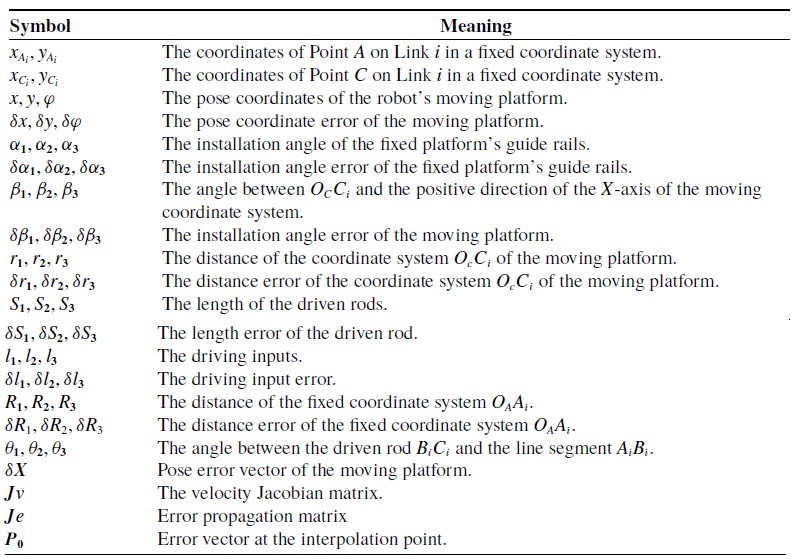
The meaning of the given symbols.
The meaning of the given symbols(continued).



