


NOMENCLATURE
- ADCS
-
Attitude Determination and Control System
- ALSAT-2
-
Algerian satellite
- SST
-
Senseur Stellaire
- MAS
-
Initial Acquisition mode
- MGT
-
Corase Pointing mode
- MNO
-
Nominal mode
- MCO
-
Orbital Control mode
1.0 INTRODUCTION
Microsatellites for Earth observation have emerged as a strong trend over the last two decades, being essentially driven by the benefits of electronics miniaturisation, which has made it possible to combine high mission performance and small volume/mass(Reference Sandau1). Regarding the attitude determination and control system (ADCS), the design process becomes more sophisticated than the implementation. The five major requirements governing the design are manoeuvrability, agility, accuracy, stability and durability(Reference Wertz, Everett and Puschell2). To enhance the performance, as an example we took the accuracy requirement. The use of sensor fusion algorithms even for an extended or unscented Kalman filter significantly increases the accuracy, although the use of several sensors increases the size, mass and power budgets. Currently, this constraint is surpassed by designing multifunctional devices where sensors are combined into a single unit, achieving accuracy of 0.1° (
 $1\sigma $
) for some inertial stellar compasses(Reference Brady, Tillier, Brown, Jimenez and Kourepenis3). The control based on the actuators must achieve the functions of stabilising, rotating and pointing to a desired orientation despite any external or internal torques(Reference Steyn4). The three-axis active control uses reaction wheels or control moment gyros (CMGs), where research and improvements are still needed to further increase their capability, especially for high-resolution imaging payloads. Within this framework, the reaction wheels or CMGs are often set in a pyramidal configuration, aiming to increase the angular momentum and thereby the agility. According to what was stated above, the structure should provide a strong supporting framework to house all the satellite subsystems and endure launch loads.
The Algerian Space Agency (ASAL) through its national space program has developed an Earth observation system consisting of two microsatellites: ALSAT-2A and ALSAT-2B. The system delivers high-resolution (2.5m) images in the panchromatic band, and 10m resolution for four multispectral bands. The concept adopt by ASAL in addition to the know-how transfer program also concerns acquiring satellite engineering technology and manufacturing microsatellites(Reference Argoun6). The very high-quality images produced by this system will give Algeria the ability to enhance applications such as forestry, desertification, cartography, agriculture management, natural disaster monitoring and land planning.
ALSAT-2 (Fig. 1) was the first Earth observation satellite system of the Astrosat (AS-100) family built by EADS Astrium(Reference Limouzin, Siguier and Chikouche14). The ALSAT-2 platform is based on a multipurpose flight-proven platform developed by the Centre National d’Etudes Spatiales (CNES) named MYRIAD(Reference Alary and Lambert5).
ALSAT-2B in deployable configuration.

The objective behind the development of the MYRIAD platform is a reduced size within a limited financial budget, taking advantage of the miniaturisation of technologies capable of implementing scientific missions, either as demonstrators or operational applications in different areas such as astronomy, fundamental physics or telecommunications, and Earth observation(Reference Cussac, Clair, Ultre -Guerard, Buisson, Lassalle-Balier, Ledu, Elisabelar, Passot and Rey9). All the necessary functions are implemented by this platform to fulfil the mission requirements, including attitude and orbit control, command data handling, electrical power, thermal control, storage and payload support(Reference Le Du, Maureau and Prieur13,Reference Tatry and Claire17) .
The ALSAT-2 structure is made up of four walls, four rods and three plates of a 60cm-sided cube. The four lateral panels accommodate all the equipment units (reaction wheels, OBC, star tracker, battery, S band transceiver, etc.), whereas the propulsion module is laid out on and under the lower plate(Reference Torres, Fallet, Julio, Maureau, Montel, Pittet and Prieur18). During the integration phase, these panels are open. The lower plate holds the launcher interface. The payload is supported by an upper plate fixed on the four vertical struts at each corner of the satellite. The platform thermal control is partly passive (painting, MLI) and partly active. Monopropellant hydrazine propulsion, operating in blow-down mode, was selected as the best compromise with respect to performance, reliability and cost with a mass of 4.6kg using 1N thrust for four thrusters(Reference Darnon, LeDeuff and Pillet10,Reference SerÈne and Corcoral16) . The power system consists of 15Ah Li-ion and a solar array. Two foldable panels form the solar array, which is stowed on the –Ysat face. A central computer (OBC) is used for data handling. Telemetry is communicated on an S-band transceiver capable of 20kbps, while payload data are downlinked on X-band at 60mbps(Reference Kopacz, Herschitz and Roney12). In the literature, several papers have dealt with the in-orbit performance of this platform, for example the DEMTER satellite, which was the first of the MYRIAD microsatellite family, whose ADCS architecture and in-orbit performance was presented in Ref. (Reference Buisson, Cussac and Parrot8). Reference (Reference Samason15) also presented a study on the performance of the high-pointing ADCS of the PICARD satellite. Finally, the principal aim of this paper is to show how the ADCS performance is well fulfilled, achieving the requirements of all modes.
This paper is organised as follows: The ALSAT-2B ADCS architecture is provided in Section 2 as well as the different satellite pointing functions, the four satellite operating modes and the different methods used for each. The flight results from initial acquisition up until nominal mode, including different orbit control manoeuvres, are described in Section 3.
2.0 ALSAT-2B ADCS ARCHITECTURE
2.1 Overview
As stated above, ALSAT-2B is based on the MYRIAD platform. The innovations applied in this satellite compared with previous satellites from the same platform such as DEMTER, PARASOL and PICARD, having a scientific payload as a main mission, is the ADCS subsystem and particularly the configuration of its wheels. In the previous satellites, three wheels were arranged in an orthogonal manner, whereas in ALSAT-2B, for agility purposes, four wheels were mounted in a pyramidal configuration. The second innovation is the sensor fusion of the star tracker and the three gyroscopes, aiming to increase the data available for the gyrostellar estimator. In addition, the solar arrays for ALSAT-2B were fixed, in contrast to the previous satellites where they had a drive mechanism.
Regarding the ADCS subsystem, ALSAT-2B is a three-axis spacecraft stabilised using the zero momentum-biased method. The sensors of the ADCS include three Sun sensors for Sun direction measurements and detection of eclipse, used during the initial acquisition mode, and one magnetometer for magnetic field direction measurements, also used in the initial attitude acquisition and during the coarse pointing mode. Three fibre-optic gyroscopes combined with one star tracker are initialised during the coarse pointing mode to prepare for the nominal mode. The orbit control mode uses only the gyroscopes measurements to carry out manoeuvres. In terms of the actuators, three magnetorquers are used for detumbling purposes, and thereafter for wheel unloading. Four reaction wheels mounted in a pyramidal configuration are used for momentum enhancement, thus achieving high agility. Finally, a propulsion subsystem with four thrusters with 1N thrust is used for in-plane and out-of-plane manoeuvres. Figure 2 illustrates the platform with the ADCS modules and components labelled.
ALSAT-2B platform.

2.2 ADCS operational modes
Four modes are used by ALSAT-2B, as shown in Fig. 3:
-
• MAS (Mode Acquisition et Survie), or initial acquisition and safe mode, is the first mode, in which all the equipment is initialied. It uses only the magnetometer and Sun sensors for the magnetic field and Sun direction. The magnetorques and reaction wheels are used as actuators, and pointing in this mode is toward the Sun with some rotation thereabout.
-
• MGT (Mode Grossier de Transition), or coarse transition mode; in this mode, constant Sun pointing without rotation is maintained but the three gyroscopes and star tracker are switched on to converge the gyrostellar estimator in preparation ofr the nominal mode. The transition to this mode is done through a telecommand.
-
• MNO (Mode Normal Operational), or normal mode used for imaging; this is based on gyrostellar fusion measurements and reaction wheels for performing along- and across-track manoeuvres, as well as the magnetorquers for wheel unloading. The transition to this mode is done through a telecommand.
-
• MCO (Mode Controle d’Orbite), or orbit control mode, dedicated to orbit control manoeuvres either in plane or out of plane. This uses the set of four thrusters.
ALSAT-2B ADCS modes.

2.2.1 Initial acquisition and safe mode (MAS)
The MAS mode ensures the acquisition of the initial attitude, with the –Xsat axis pointed towards the Sun, after separation from the launcher, as well as survival in the event of abnormal behaviour during the microsatellite’s life cycle. The MAS mode requirements are:
-
• To orientate the solar panels and –Xsat toward the Sun for electrical power generation.
-
• To guarantee thermal equilibrium by ensuring the satellite undergoes slow rotation around the Xsat axis.
-
• Use the minimum of equipment to increase reliability, and be totally autonomous (with no telecommands from the ground).
It is based on:
-
• The Sun direction and magnetometer measurements for angular rate estimation.
-
• The four reactions providing gyroscopic stiffness around the Xsat axis, to ensure dynamic stability despite disturbing torque, especially during eclipse.
-
• The three magnetorquer rods for the Xsat axis direction control, which is pointed toward the Sun.
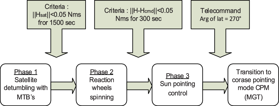
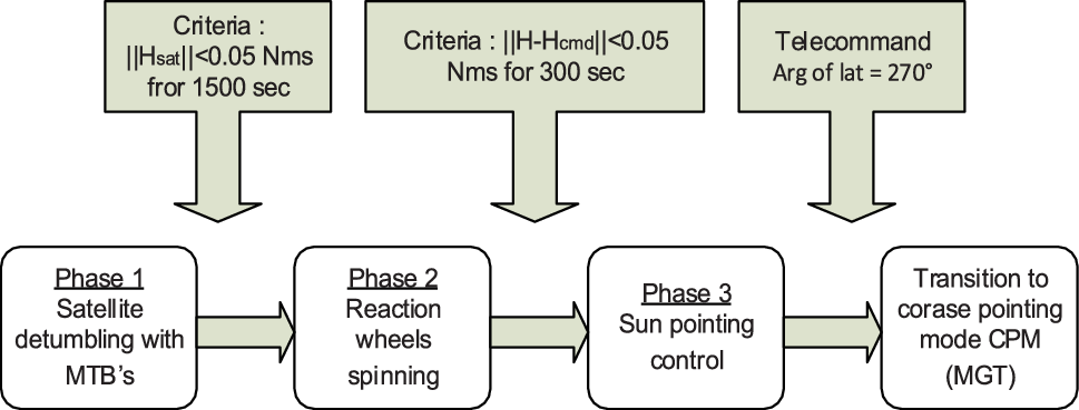
This acquisition and safe hold mode is organised into three phases, as shown in Fig. 4.
-
‐ Phase 1 (detumble submode): Just after separation from the launcher, high rates are observed due to tumbling. These high rates are reduced by magnetic damping using MTBs. The set point of the angular momentum is 0.05Nms for about 1,500s, being a criterion for the transition to the next phase.
Figure 4.Initial acquisition mode phases.

The first term of the magnetic momentum
 $\overrightarrow {{M_{11}}\;} $
is determined from the derived Earth magnetic field
 $\vec B$
. The second term of the command
 $\overrightarrow {{M_{12}}} $
is derived from the estimated satellite angular momentum
 ${\vec H_{SAT}}$
such that
 \begin{equation}\vec M = {\vec M_{11}} + {\vec M_{12}} = - \frac{{{I_{SAT}}}}{{{\tau_{11}}{B^2}}}\overrightarrow {\dot B} + \frac{{\vec B \wedge \left( { - \frac{{{{\vec H}_{SAT}}}}{{{\tau_{12}}}}} \right)}}{{{B^2}}}\end{equation}
where
 $\vec M$
is the total magnetic momentum,
 ${\vec M_{11}}\;$
is the first term of the magnetic momentum,
 ${\vec M_{12}}$
is the second term of the magnetic momentum,
 ${I_{SAT}}$
is the satellite inertia,
 $\vec B$
is the Earth magnetic field,
 $\overrightarrow {\dot B} $
is the derived Earth magnetic field,
 ${\vec H_{SAT}}$
is the satellite angular momentum,
 ${\tau_{11}}$
is the filter time constant (first term) and
 ${\tau_{12}}$
is the filter time constant (second term).
-
‐ Phase 2 (spinning submode): The wheels are switched on and spin until reaching an angular momentum along the Xsat axis with a magnitude of −0.15Nms. Here, the criterion to be satisfied to move on to the next phase is based on the difference between the total angular momentum and the commanded angular momentum, compared with a threshold of 0.05Nms during at least 300 s. In this phase, the command applied to the MTB is implemented using the equation
(2)
\begin{equation}{\vec M_2} = \frac{{\vec B \wedge \left( { - \frac{{{{\vec H}_{TOT}} - {{\vec H}_{cmd}}}}{\tau }} \right)}}{{{B^2}}}\end{equation}
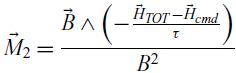
where
 ${\vec M_2}$
is the Total magnetic momentum,
 ${\vec H_{cmd}}$
is the commanded angular momentum,
 ${\vec H_{TOT}}$
is the total angular momentum (satellite + reaction wheel angular momentum) and
 $\tau $
is the filter time constant
-
‐ Phase 3 (Sun acquisition submode): This is the converged phase of the mode, where the solar panels and–Xsat are pointing toward the Sun within reduced limits.
The control is achieved by two commands: the first term of the command
 $\overrightarrow {{M_{31}}} \;$
brings the total angular momentum to the desired set point, while the second term of the command
 $\overrightarrow {{M_{32}}} \;$
determines the orientation of the total angular momentum to the Sun direction:
 \begin{equation}{\vec M_3} = {\vec M_{31}} + {\vec M_{32}}\end{equation}
where
 \begin{equation}{\vec M_{31}} = \frac{{\vec B \wedge \left( { - \frac{{\left( {{{\vec H}_{TOT}} - {{\vec H}_{cmd}}} \right)}}{{{\tau_{31}}}}} \right)}}{{{B^2}}}\end{equation}
and
 \begin{equation}{\vec M_{32}} = \frac{{\vec B \wedge \left( {\frac{{\left[ {{{\vec H}_{TOT}} \wedge \left( {\vec S \wedge {{\vec H}_{TOT}}} \right)} \right]}}{{{\tau_{32}}{{\vec H}_{TOT}}}}} \right)}}{{{B^2}}}\end{equation}
where
 ${\vec M_3}$
is the total magnetic momentum,
 ${\vec M_{31}}$
is the first term of the magnetic momentum,
 ${\vec M_{32}}$
is the second term of the magnetic momentum,
 ${\vec H_{cmd}}$
is the commanded angular momentum,
 ${\vec H_{TOT}}$
is the total angular momentum (satellite + reaction wheel angular momentum),
 $\vec S$
is the solar direction unit vector,
 ${\tau_{31}}$
is the filter time constant (first term) and
 ${\tau_{32}}$
is the Filter time constant (second term).
2.2.2 Coarse pointing mode (MGT)
The coarse transition mode (MGT) is a control mode allowing the acquisition of correct pointing (to within a few degrees) with respect to the geocentric or heliocentric pointing command from any initial attitude. It uses magnetic measurement and control and requires knowledge of the absolute position of the satellite with sufficient precision (to calculate an adequate magnetic field command). It is a robust mode since it requires little equipment (magnetometer, magnetorquer and reaction wheels). Compared with previous microsatellites in the MYRIAD series, the special feature of ALSAT-2B is that it uses four wheels placed in a pyramidal configuration, which allows greater capacity in terms of angular momentum. The need for this transition mode is mainly linked to the stellar sensor used in MNO, which must not be dazzled at the transition to this mode. MGT is also used to converge the gyrostellar estimator under controlled conditions.
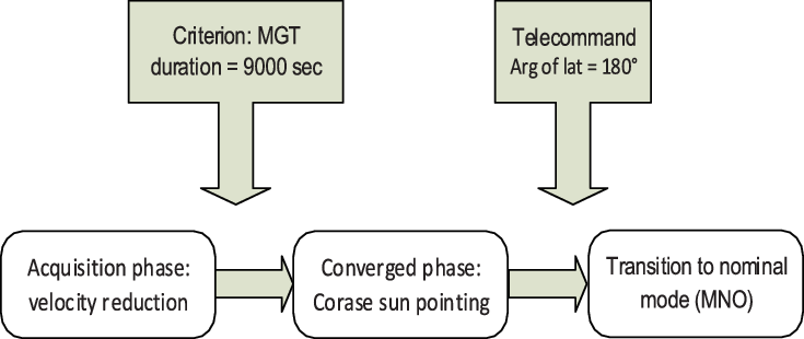
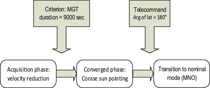
Functionally, the MGT is composed of two phases:
-
• An acquisition phase, intended to reduce the satellite angular velocities and acquire rough pointing of the set point (on ALSAT-2B, the set point is heliocentric). The need for this phase is due to the change of control between the MAS and the MGT, which can cause significant disturbances in satellite speed (passage from a wheel angular momentum on Xsat to an angular momentum on Ysat).
-
• A so-called converged phase during which the heliocentric pointing is improved to enter the MGT output specifications. Figure 5 shows a schematic diagram of the MGT phases.
Figure 5.MGT phases.
The principle of MGT, or compass mode, is to create a magnetic moment
 ${\vec M_{COM}}$
on board the satellite in the direction
 $\overrightarrow {{b_0}} $
that the Earth’s magnetic field would have if the satellite were well pointed. In the case where the satellite is not well pointed, a magnetic couple is created by the action of the commanded magnetic moment on the surrounding magnetic field
 $\vec B$
, which will naturally tend to align the vector
 $\overrightarrow {{b_0}} $
following
 $\vec B$
in the same manner that a compass needle aligns with the local magnetic field.
A term depending on the derivative of the measured magnetic field introduces damping into the control loop.
The control is then optimised by removing the component of the magnetic moment parallel to the measured field, which would in any case create no torque.
Finally, the magnetic moment is normalised with respect to the direction of the ordered moment, taking into account the maximum capacity of the MTBs.
The
 ${\vec M_{COM}}$
controlled magnetic moment is given by
 \begin{equation}\vec{M}_{0} =\frac{K\overrightarrow{\mathop{\dot{b}_{0} } }+D\left(\overrightarrow{\mathop{\dot{b}_{0} }}-\overrightarrow{\dot{b}}\right)}{\vec{B}}\end{equation}
 \begin{equation}\overrightarrow {{M_1}} = \overrightarrow {{M_0}} - \left( {\overrightarrow {{M_0}} \;.\;\vec b} \right).\vec b\end{equation}
 \begin{equation}\overrightarrow {{M_{COM}}} = \frac{{\overrightarrow {{M_1}} }}{{\max \left( {1\;,\;\left| {\frac{{{M_{1x}}}}{{{M_{max}}}}} \right|\;,\left| {\frac{{_{1y}}}{{{M_{max}}}}} \right|\;,\;\left| {\frac{{{M_{1z}}}}{{{M_{max}}}}} \right|} \right)}}\end{equation}
where
 $\vec b$
is the direction of the measured magnetic field vector,
 $\vec b = \;\frac{{\vec B}}{{\vec B}}$
,
 ${\vec b_0}$
is the direction of the commanded magnetic field vector,
 $K$
is the proportional gain (scalar),
 $D$
is the derived gain (matrix), and
 ${\vec M_{max}}$
is the maximum capacity of the MTBs.
2.2.3 Normal mode (MNO)
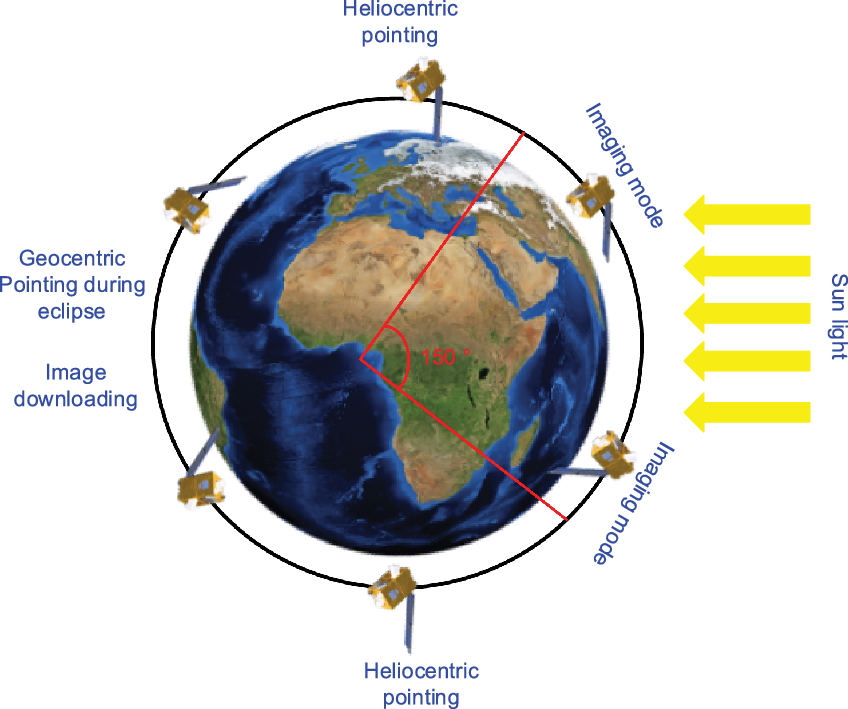
The MNO mode is the operational mode of the satellite, implementing the pointing modes required to perform imaging as well as attitude manoeuvres to achieve pointing. Attitude estimation is performed by the stellar sensor, the measurement of which is combined with that of the gyroscopes to ensure better availability of attitude measurements during the mission. Control is enabled by the four reaction wheels arranged according to an optimised pyramidal configuration, with respect to the control requirements for the three axes of the satellite, while the magnetorquers ensure the desaturation of the wheels. The attitude of the satellite in MNO is as follows:
-
• Heliocentric pointing, i.e. the solar panel is pointed towards the Sun with sinusoidal motion, with rotation of
$\sim$
0.025°/s about its – Xsat axis to avoid dazzling of the star tracker (SST) by the ground at the poles. -
• Geocentric pointing in eclipse: the Xsat axis faces the Earth to allow data download.
-
• Mission pointing for imaging, with respect to the local orbital reference frame, corresponding either to the manoeuvring phases during imaging missions or to the day/night or night/day maneuvers. Figure 6 illustrates the different satellite pointing modes.
Figure 6.Different pointings of ALSAT-2B.

The estimation process can be split into three phases(Reference Ghezal, Polle, Rabejac and Montel11) (Fig. 7):
-
‐ Prediction of the state vector: From the estimated quaternion at the previous time step and the gyro measurement, a predicted quaternion is calculated. The predicted drift is equal to the estimated drift at the previous time step.
-
‐ Innovation calculation: The angular difference between the SST-measured quaternion and the estimated quaternion is calculated at the SST measurement date, with referecen to the SST axes.
-
‐ Correction: The predicted attitude quaternion is corrected by the innovation, previously multiplied by the estimator gain.
ALSTA-2B gyrostellar estimator architecture.

Prediction
The prediction is based upon the following kinematics equation:
 \begin{equation}\dot Q = \frac{1}{2}Q \otimes \Omega \end{equation}
where
 $\Omega=\left[\begin{array}{c}0\\ \underline{\underline{\omega}}\end{array}\right], \underline{\omega}$
is the angular velocity rate with respect to the inertial frame, expressed in the satellite frame and
 $ \otimes $
is quaternion multiplication.
The equation is discretised using the Wilcox method:
 \begin{equation}\left\{\begin{array}{c} {\hat{Q}_{N/N-1} = \hat{Q}_{N-1/N-1} \otimes \delta Q_{N} } \\[5pt]
\hat{\!d}_{N/N-1} = \ \hat{\!d}_{N-1/N-1} \end{array}\right.\end{equation}
where
 $\hat{Q}_{N/N}$
is the estimated attitude quaternion with respect to the inertial measurement frame at
 ${T_N}$
,
 $\hat{Q}_{N/N-1}$
is the predicted attitude quaternion with respect to the inertial measurement frame at
 ${T_{N - 1}}$
and
 $\hat{d}_{N/N-1}$
is the predicted gyro drift at
 ${T_N}$
, estimated at
 ${T_{N - 1}}$
because no gyro drift evolution model is available.
Innovation computation
The predicted quaternion defines the rotation between the inertial frame and the satellite frame (body frame), expressed in the SST measurement frame:
 \begin{equation}\hat{Q}_{IST} = \hat{Q}_{IB} \otimes Q_{BST}\end{equation}
The innovation is obtained through a multiplication by the SST measurement:
 \begin{equation}\left(\begin{array}{c} {0} \\[1pt] {\Delta \theta_{INV}} \end{array}\right)=
\left(\begin{array}{c} {0} \\[5pt] {\Delta \theta_{INV,x} } \\[5pt] {\Delta \theta_{INV,y} } \\[5pt] {\Delta \theta_{INV,z} } \end{array}\right)=2 \hat{Q}_{IST} \otimes Q_{IST}^{MST}\end{equation}
where
 $Q_{_{}IS{T_{}}}^{MST}$
is the SST measurement, expressing the rotation between the inertial frame and the SST measurement frame and
 $\Delta {\theta_{INV,x}},\Delta {\theta_{INV,Y}},\Delta {\theta_{INV,z}}$
are the Euler angles of the rotation between the predicted and measured attitude of the satellite, expressed in the SST reference.
Correction
The correction vector
 ${X_{COR}}$
to be applied to the predicted state vector is
 \begin{equation}{{\bf{X}}_C} = \left( {\begin{array}{c}{\theta_C^{ST}}\\[5pt]
{{d_C}}\end{array}} \right) = \left({\begin{array}{c}{\theta_{XC}^{ST}}\\[5pt]
{\theta_{YC}^{ST}}\\[6pt]
{\theta_{ZC}^{ST}}\\[6pt]
{{d_{XC}}}\\[3pt]
{{d_{YC}}}\\[3pt]
{{d_{ZC}}}\end{array}} \right) = {{\bf{K}}_{KAL}}{\bf{\Delta }}{\theta_{INV}}\end{equation}
where
 $\theta_{XC}^{ST},\theta_{YC}^{ST},\theta_{ZC}^{ST}$
are the attitude corrections expressed in the SST measurement frame,
 ${d_{XC}},{d_{YC}},{d_{ZC}}$
are the drift corrections and
 ${{\bf{K}}_{KAL}}$
is the correction gain as a constant matrix with dimensions of 7 × 3.
The correction Euler angles are then transferred from the SST measurement frame to the satellite reference frame:
 \begin{equation}\theta_C^B = {Q_{BST}}\theta_C^{ST}\hat{Q}_{BST}\end{equation}
The estimated attitude at date T N is then
 \begin{equation}\hat{Q}_{N/N} = \hat{Q}_{N/N-1} \otimes Q_{C,N}\end{equation}
And the estimated drift is
 \begin{equation} \hat{\!d}_{N/N} =\ \hat{\!d}_{N/N-1} +d_{C,N}\end{equation}
Agility performance has become one of the key factors in developing/operating modern satellite systems, especially for Earth imaging, because it determines the number of imaging targets available within the duration of a given pass.
Note here that the pyramidal configuration is one of the key features of ALSAT-2 satellites, being the first time that it has been applied on board, aimed to improve the satellite momentum to be agile and to ensure back/forward as well as along/across-track imaging (Fig. 8)(Reference Benzeniar and Meghabber7).
ALSAT-2B reaction wheel mounted in pyramid configuration.

The control process uses a proportional–derivative controller during the converged nominal mode:
 \begin{equation}{C_{com}} = - {K_p}\theta - {K_d}\dot \theta \end{equation}
where
 ${C_{com}}$
is the torque applied to the wheels,
 $\theta $
is the estimated angle from the star tracker,
 $\dot \theta $
is the estimated velocity from the gyroscope,
 ${K_p}$
is the proportional gain and
 ${K_d}$
is the derivative gain.
The reaction wheels generate maximum torque if two wheels rotate in one direction while the other two rotate in the opposite direction (with respect to the Y- and Z-axes).
 \begin{align}
{C_x} & = 4 \times {C_{wheel}} \times sin\beta\nonumber \\[3pt]
{C_y} & = 4 \times {C_{wheel}} \times cos\beta \times cos\alpha \\[3pt]
{C_z} & = 4 \times {C_{wheel}} \times sin\alpha \times cos\beta\nonumber \end{align}
where
 ${C_{wheel}}$
is the elementary torque generated by a single wheel
We suppose
 $\vec{h}_{i}$
the angular momentum of wheel i (i = 1–4). All four wheels contribute to generate the total angular momentum of the satellite
 $\vec H$
:
 \begin{equation}{\vec H_{sat}} = \mathop \sum \limits_{ = 1}^4 \overrightarrow {{h_i}}\end{equation}
The angles α and β have values of 48° and 19° respectively, and the projection of the four h i vectors on the X–Y–Z axes is given by the relation
 \begin{align}\left[ \begin{array}{c}{{H_x}}\\[4pt]
{{H_y}}\\[4pt]
{{H_z}}\end{array} \right] =
\left[ \begin{array}{c@{\quad}c@{\quad}c@{\quad}c} - {\rm{sin}}\beta & {{\rm{sin}}\beta } & {{\rm{sin}}\beta } & { - {\rm{sin}}\beta }\\[4pt]
{{\rm{cos}}\alpha {\rm{cos}}\beta } & {{\rm{cos}}\alpha {\rm{cos}}\beta } & { - {\rm{cos}}\alpha {\rm{cos}}\beta } & { - {\rm{cos}}\alpha {\rm{cos}}\beta }\\[4pt]
{{\rm{cos}}\alpha {\rm{sin}}\beta } & {{\rm{cos}}\alpha {\rm{sin}}\beta } & {{\rm{cos}}\alpha {\rm{sin}}\beta } & {{\rm{cos}}\alpha {\rm{sin}}\beta }\end{array} \right]
\left[ \begin{array}{c} {{h_1}}\\[4pt]
{{h_2}}\\[4pt]
{{h_3}}\\[4pt]
{{h_4}}\end{array} \right]\end{align}
Wheel unloading or desaturation is enabled by the three magnetorquers using the following control law:
 \begin{equation}{\vec C_{desat}} = {K_p}\left( {{{\vec H}_{com}} - {{\vec H}_{sat}}} \right) + {K_i}\smallint \left( {{{\vec H}_{com}} - {{\vec H}_{sat}}} \right)dt\end{equation}
The magnetic moment command to the magnetorquers is then given as
 \begin{equation}\vec M = \frac{{{{\vec C}_{desat}} \otimes \vec B}}{{{B^2}}}\end{equation}
where
 ${\vec C_{desat}}$
is the desaturation torque applied to the wheels,
 ${\vec H_{com}}$
is the commanded angular momentum,
 ${\vec H_{sat}}$
is the measured satellite angular momentum,
 ${K_p}$
is the proportional gain,
 ${K_d}$
is the integral gain,
 $\vec M$
is the applied magnetic moment and
 $\vec B$
the Earth’s magnetic field.
Here, we give a brief description of the manoeuvre, but first we should distinguish between the day/night or night/day transitions and imaging manoeuvre. The former is dedicated to avoiding the star tracker being dazzled by the Earth, hence providing good performance in terms of availability. This transition manoeuvre consists of three profiles, starting with an acceleration to get a maximum torque according to
 \begin{equation}{\vec w_{{\rm{max}}allowed}} = \frac{{{{\vec H}_{{\rm{max}}wheel}}}}{{\mathop {{\rm{max}}\left| {{A_{wheel}}\left( i \right)} \right|}\limits_{i = 1,4} }}\end{equation}
 \begin{equation}{\vec H_{wheel}} = G \cdot {\vec H_{sat}} = \vec w \cdot G \cdot {I_{sat}}\end{equation}
where
 $\;{{{\vec{\rm w}}}_{{\rm{maxallowed}}}}$
is the maximum allowable angular velocity,
 $\;{{{\vec{\rm H}}}_{{\rm{wheel}}}}\,,\,{{\vec{\rm H}}_{{\rm{sat}}}}$
are the wheel and satellite angular momentum, I
sat is the satellite inertia (3 × 3 matrix), G is a 3 × 4 matrix used to extract the wheel momentum from the satellite momentum and
 ${\rm{\;}}{{\rm{A}}_{{\rm{wheel}}}} = {\rm{G}} \cdot {{\rm{I}}_{{\rm{sat}}}}$
(a four-dimensional vector).
Once the maximum velocity has been reached, a constant velocity is commanded, to avoid a long transient response before going to a deceleration profile. This is how the manoeuvre is implemented as shown in Figure 9.
Slew manoeuvre profile.

Now, for an imaging manoeuvre, we just add a settling profile (the fourth profile) to ensure perfect stability (30µrad peak to peak /4Hz) during imaging. The profile duration depends on the manoeuvre amplitude.
2.2.4 Orbit control mode (MCO)
The orbit control mode is intended to modify the orbital parameters. The off-modulation thrusters perform attitude control for the three axes. Thus, the thrusters provide both thrust, making it possible to correct the orbit, as well as attitude control. The propulsion subsystem, composed essentially of a tank sized to carry a maximum mass of 4.7kg of hydrazine, operates according to the “blow down” mode with tank pressure in the range from 24 to 5.5bar. The tank also contains the helium necessary for pressurisation. The technology used to separate the pressurising gas from the hydrazine is an impermeable elastomeric membrane. It guarantees a gas-bubble-free draw regardless of the specified environmental conditions. A thermal control function of the tank (by software) is implemented on ALSAT-2B to limit the operating pressure at the beginning of life. At the beginning of life, the thermal control of the tank ensures a temperature of 20°C, with a maximum pressure of 24bar (at 30°C). Four 1N thrusters, each fitted with two solenoid valves in series, are controlled by the power control and distribution unit (PCDU) to apply thrust. The thrusters can operate in continuous or pulsed mode. Figure 10(a) illustrates the ALSAT-2B propulsion subsystem architecture, while Fig. 10(b) shows the design implemented for the propulsion subsystem.
(a) ALSAT-2B propulsion subsystem architecture. (b) ALSAT-2B propulsion subsystem design.

The exit from the MCO mode is managed automatically. When the total number of pulses produced by the four thrusters reaches the requested value, it returns to MNO mode. Before the thrust execution, the ground programs one heliocentric orbit pointing, and after the thrust, two more heliocentric orbits are carried out to recharge the batteries and converge the payload thermal control. We distinguish three types of rallies towards the thrust attitude:
-
‐ A slew manoeuvre along the pitch axis for in-plane orbit correction (alignment of the thrust direction with the velocity vector)
-
‐ A slew manoeuvre along the roll axis for out-of-plane orbit correction (alignment of the thrust direction normal to the orbit plane)
-
‐ A combined roll/pitch slew manoeuvre, bringing the satellite Xsat axis into the plane containing the velocity vector and the normal to the orbit, which makes it possible to carry out a combined correction of the semi-major axis and the inclination. Optimal efficiency is obtained when the satellite Xsat axis is located at 45° from the velocity vector and from the normal to the orbit. The attitude measurement comes from the three gyroscopes; this allows these manoeuvres to be performed at any orbital position, since measurements are available continuosuly from the gyroscopes (with no need for a solar/stellar measurement), but in return this requires initialisation of this measurement. The estimator initialisation is performed at the beginning of the MCO mode using the estimate provided from the MNO mode.
3.0 IN-ORBIT LAUNCH EARLY OPERATIONS RESULTS
This section presents the in-orbit results obtained from telemetry during the launch early operations (LEOP), to show the performance and how it fulfils the stated requirements.
3.1 Initial attitude acquisition mode (MAS)
ALSAT-2B was launched by PSLV-C35 on 26 September 2016 at 04:42:00 UTC. After injection of the satellite from the launcher, the satellite was tumbling at less than 3°/s around its three axes. At 1,800s from separation, the solar array was automatically deployed, and the initial acquisition mode started. The main performance requirements for this mode are:
-
‐ Convergence duration of less than 18,000s.
-
‐ The –Xsat axis should pointed toward the Sun at better than 30° once the satellite is in the convergence phase
Note here that the time used is the OBC time before synchronisation, which is set by default to 20/07/2000.
MAS convergence is attained in minimal time, thanks to the small angular rate at injection.
According to Fig. 11, which shows the evolution of the angular rates issued from the magnetometer and the Sun sensor measurements, note that the initial rates were about 0.01°/s and the duration of the first phase was 8,135s, shorter than the duration obtained during simulations. This is mainly because the rate at separation was about 1°/s. Peaks are observed at the eclipse exit, but the rates converge rapidly.
Angular rates versus MAS phases.

Figure 12 shows the evolution of the –Xsat direction toward the Sun (Sun pointing) and the solar array pointing, just after satellite injection. During the first submodes, the amplitude of the Sun pointing error is high, but at the beginning of the third phase, the pointing starts to converge and leads to under 30° for both parameters during the third phase.
Sun pointing and solar array pointing versus MAS phases.

The angular momentum is illustrated in Fig. 13. For the first submode, note that the angular momentum amplitude was under 0.05Nms and the transition to the next phase starts with peak values this are mainly due to the spin-up of the four wheels when creating the angular momentum. The third submode is enabled once, and the transition criterion (
 ${\|\vec H_{sat}} - {\vec H_{cmd}}\| \lt 0.05{\rm{Nms}}$
during 300s) is satisfied. Note the appearance of peak values caused when changing the control laws from one submode to another.
Angular momentum versus MAS phases.

Table 1 presents the in-flight duration of each submode compared with the design predictions. Note that the obtained durations are shorter than the predicted values.
Duration of MAS mode phases

3.2 Coarse pointing mode (MGT)
A transition to the coarse pointing mode (MGT) is carried out through a telecommand uploaded from the ground. It is executed during the eclipse phase, exactly at 270° argument of latitude. The choice of this position is motivated by the fact that, when the satellite enters daylight, it will have sufficient time to charge the batteries and hence be ready to go through the next eclipse phase.
Figure 14 illustrates the angular error between the magnetic field measured by the magnetometer and the magnetic command. The estimated error angle is better than 20° and is obtained approximately 2,220s after the transition to MGT mode, which is in accordance with the ADCS budget (maximum 8,000s).
Error angle between measured magnetic field and magnetic command.

After convergence of the MGT, the estimated worst-case angular error is on the order of 6°, which again complies with the ADCS budget (maximum 11°).
The actuation rates of the MTBs during the converged phase are in accordance with expectations. The low values observed are due to low solar activity, which limits the level of the disturbing couples (Table 2).
MTB actuation rates over one orbit (6,000s)

During the converged phase of the MGT mode, the star tracker and the three gyroscopes are turned on, hence the gyrostellar estimator is initialised to be prepared for the nominal mode. Figure 15 shows the estimated drift of the three gyroscopes from initialisation until the convergence of the gyrostellar estimator. In the current case, convergence of this estimator was achieved within 2,10 s. The graph also shows some periods during which no drift was measured; this is due to the star tracker being blinding by the Earth.
Estimated gyroscopes drift.

Regarding the star tracker, no transient is observable on the attitude. The attitude estimation is mainly based on the star tracker measurements. It converges in a few cycles and suffers little impact from the error in the estimation of drifts. Figure 16 shows the estimated attitude issued from the gyrostellar estimator; note here that the attitude is constant.
Estimated attitude (quaternion) from the gyrostellar estimator.

Figures 17 and 18 highlight that the innovations are in line with the predictions, with typical values below than
 $2 \times {10^{ - 4}}$
rad for the transverse axes and
 $5 \times {10^{ - 4}}$
rad on the line-of-sight axis of the star tracker. Higher values are observed near the dazzling phases by the ground (disturbance of star tracker measurements by the Earth and compensation for gyroscope drifts in the pure propagation phases) (Figs 17 and 18).
Innovations on star tracker transverse axes.

Innovations on star tracker line-of-sight axes.

3.3 Nominal mode (MNO)
The transition to MNO took place on 2016/09/27 at 19:14:55.820. The convergence in attitude was rapid, the initial pointing on the order of 3.8° was absorbed in less than 1min, then we observe pointing errors on the order of 500µrad on the Y-axis and less than 200µrad on the X and Z-axes. The pointing error peak on the Y-axis is related to the desaturation of the wheels (the angular momentum on the Y-axis for the MGT mode). On the Astrosat 100 platform, there was no open-loop compensation for the desaturation of the wheels; rather, it was the compensation for the pointing error induced by the actuation of the MTBs that ensured the desaturation (Figs 19 and 20).
Pointing error evolution from the MGT to MNO modes.

Zoom out of the pointing error evolution during the convergence of the MNO mode.

The wheels were desaturated nominally at 3,600s after entering MNO, and the wheel speed was less than 200rpm. After desaturation, the estimated pointing error was less than 500µrad outside the transient phases as shown in Fig. 21, which illustrates the evolution of the speed of the wheels. The wheel desaturation was authorised automatically via the three magnetorquers once a speed of 1,040rpm was reached in imaging mode. Another case of unloading generally happens when there are day/night or night/day manoeuvres, or when manoeuvring to obtain an image across the track.
Reaction wheel desaturation.

The results confirm that the pyramidal configuration of the wheels has proven its efficiency in terms of agility and capability to increase the satellite angular momentum. Figure 22 presents the evolution of the speed of the four reaction wheels through the different ADCS modes until the mission was ready for imaging, revealing that the speed of the wheels was constant at around 2,500rpm during the MAS mode. The same effect is seen in the MGT mode, but with a lower value of around 1,800rpm. A transition to the MNO mode provides a new command to the wheels during one orbit (6,000s), the wheels are desaturated and follow a heliosinusoidal command (the solar panels are pointed directly to the Sun with a small revolution about the Xsat axis). Once an imaging mission plan is uploaded, also including different day/night and night/day manoeuvres, thanks to this configuration, one can see the variation from upper to lower values as well as the zero crossing case for each wheel, which has no effect on the satellite angular momentum in this case.
Reaction wheel speed evolution through different modes.

The analysis of the ADCS performance in terms of the pointing error during the imaging mode is shown in Fig. 23 when the first five image acquisitions took place during their visibility. The upper graphs show the evolution of the estimated pointing accuracy by the gyrostellar estimator during the whole visibility. The definition of the guidance type is 1 for geocentric pointing, 2 for heliocentric pointing, 3 for transition manoeuvre and 4 for image acquisition. The performance fulfils the specifications with an estimated pointing accuracy less than 500µrad when carrying out imaging. The discontinuities of guidance at the end of image acquisition or at the start of the heliocentric/geocentric manoeuvre induce a significant pointing error (about 2,000µrad). These pointing errors are quickly absorbed by the ADCS (in less than 20s) and thus have no impact on the image acquisition; Fig. 24 shows a zoom out of the pointing error during imaging.
Pointing error versus guidance type and payload state (OFF/image acquisition).

Zoom out of the pointing error versus guidance type and payload state (OFF/image acquisition).

Realised DV during transfer plan

3.4 Orbit control mode (MCO)
Twenty-two manoeuvres have been performed to increase the orbit and to correct the inclination, as illustrated in Table 3. Two manoeuvres per day of a few m/s have been planned at relevant arguments of latitude to reach the frozen eccentricity. To fulfil the electrical, thermal and ADCS constraints (no wheel desaturation during thrust, etc.) and the minimum delay between two successive manoeuvres (1.5 orbits), the maximum delta V to be used per orbit during transfer should be less than 3m/s. The strategy applied to reach the nominal orbit is to use a set of in-plane and out-of-plan manoeuvres for the semi-major axis and the inclination with less fuel consumption.
The estimated pointing error during the thrust for two cases is illustrated in Figs 25 and 26: the first one with small delta V (0.5m/s), and the other with the highest delta V (2.5m/s). Note that the drift of the gyroscopes affects the pointing error when delta V is higher due to the long duration of the thrust.
Estimated pointing error for a 0.5m/s ΔV.

Estimated pointing error for a 2.5m/s ΔV.

4.0 CONCLUSION
After the successful launch of ALSAT-2B, thanks to the reduced angular velocity at injection and well-estimated disturbing torques, the satellite started the initial acquisition (MAS) mode with performance better than predicted by simulation. The estimated rates measured from the Sun sensors and magnetometer were acceptable and helped the actuators (magnetorquer rods and reaction wheel) to converge to the third phase of this mode rapidly. Next, the transition to the coarse mode (MGT mode) was very easy without any constraints for either the satellite or ground control centre.
In addition, the convergence of this mode was better than expected, and the gyrostellar estimator when first initialised converged quickly, enabling an easy passage to the nominal mode.
The pointing accuracy during imaging remains within the specified limits. The performance of the gyrostellar estimator that was used for the first time on this platform was very satisfactory during the nominal mode (MNO mode), and the star tracker offered 89% time availability, providing considerable robustness in the MNO mode. Also, the pyramidal configuration of the wheels enhanced the satellite angular momentum, leading to very good agility (along/cross-track manoeuvres) of the satellite. The performance of the propulsion subsystem based on hydrazine monopropellant during the orbital manoeuvres was fully satisfactory in terms of thrust efficiency and stability. In general, the convergence of all modes turned out to be remarkably shorter than expected.