
Introduction
Lithium (Li)-metal secondary batteries (LMBs) are one of the most promising energy storage technologies to be used in future electric vehicles and grid storage, due to their ultra-high theoretical capacity (3860 mAh/g) and low redox potential (−3.04 V versus standard hydrogen potential, H2/H+).[Reference Whittingham1] However, the successful usage of LMBs is limited due to the undesired formation of Li electrodeposits in the form of filaments or dendrites, which cause mechanical deformation of the electrode and in the worst case internal electric short circuit.[Reference Yamaki, Tobishima, Hayashi, Keiichi Saito, Nemoto and Arakawa2–Reference Kushima, So, Su, Bai, Kuriyama, Maebashi, Fujiwara, Bazant and Li5] There is significant foregoing research regarding the harmful influence of randomly shaped Li electrodeposits on LMB's performance, based upon which many experimental methods to suppress undesired dendritic formation have been developed.[Reference Wu, Cao, Geng and Wang6–Reference Wang, Zeng, Hong, Xu, Yang, Wang, Duan, Tang and Jiang12] A number of theoretical studies[Reference Monroe and Newman13–Reference Enrique, DeWitt and Thornton17] have investigated the morphological evolution of Li electrodeposits; however, only one work[Reference Yurkiv, Foroozan, Ramasubramanian, Shahbazian-Yassar and Mashayek16] has included the effect of the stress field in the calculations of Li dendrites/filaments formation. Most of these studies show that the stress field originated from the electrodeposited Li plays a crucial role in the growth rate and morphology of Li electrodeposits. Although these studies discuss the effect of stress on the Li electrodeposition, the clear evidence to what extent the elastic energy contribution influences solid Li growth have not been provided. Only recently, Wang et al.[Reference Wang, Zeng, Hong, Xu, Yang, Wang, Duan, Tang and Jiang12] have shown that stiffness of the substrate on which Li electrodeposits has a direct influence on the shape and rate of solid Li deposition. In particular, they show that Li dendrites/filaments formation in the presence of carbonate-based electrolytes can be suppressed by means of soft substrates, where the generated residual stress can be released. It should be noted that the conclusions made by Wang et al. would not be possible without a significant contribution from the prior work by Kushima et al.[Reference Kushima, So, Su, Bai, Kuriyama, Maebashi, Fujiwara, Bazant and Li5]. They show that using in-situ environmental transmission electron microscopy buildup stress and its relaxation at the surface of electrodeposited Li are directly responsible for the initiation of filaments formation.
The primary objective of this work is to explore the stress influence on the Li electrodeposition in LMBs by using the phase-field model (PFM). A supporting objective is to extend the state-of-the-art protective strategies used against undesired sharp filaments formation. The present study uses our previously developed PFM of Li electrodeposition[Reference Yurkiv, Foroozan, Ramasubramanian, Shahbazian-Yassar and Mashayek16] with the incorporation of a plastic model, which allows the analysis of the elasto-plastic deformation during Li electrodeposition. The PFM simulations taking into account the mechanical response of the material depend upon the constitutive relation between the stress and strain tensor. The present work uses anisotropic stress–strain relationship to better understand the elastic energy contribution to the Li filaments growth in the presence of hard and soft Li deposition matrix.
Model formulation
The modeling approach is based upon our previously reported model[Reference Yurkiv, Foroozan, Ramasubramanian, Shahbazian-Yassar and Mashayek16] and other prior reports[Reference Guyer, Boettinger, Warren and McFadden18–Reference Bazant20] following fundamental thermodynamic and electrochemical concepts of electrodeposition. It should be emphasized that, although the present model is based on Guyer et al.[Reference Guyer, Boettinger, Warren and McFadden18, Reference Guyer, Boettinger, Warren and McFadden19] work, we are not aiming to resolve the detailed electric double layer as described in the Guyer et al. work. We rather borrow the fundamental principles of PHM of electrodeposition and we focus on the global aspects of the stress influence on the Li filaments growth. Thus, only a brief summary is given here, focusing on the mechanical part in some more details as it is a key element in the present report. The model is based upon physical diffusion-conservation laws formulated in the continuum manner using partial differential equations and then discretized using finite element method[Reference Tonks, Gaston, Millett, Andrs and Talbot21] and solved computationally. A two-dimensional (2D) domain is used for all calculation presented in this paper.
The investigated system is composed of two phases, that are the Li solid phase and the liquid electrolyte phase. In order to describe the electrodeposition of Li-ions at the interface between the liquid and solid phases (i.e., narrow few nanometers interface), different mechanical and physico-chemical processes must be taken into account. In particular, these include ions diffusion and electro-migration in the liquid phase, electrical conductivity in the solid phase, anisotropic solid-state growth, charge-transfer reaction, and elasto-plastic deformation of Li solid phase upon growth. It should be noted that the charge transfer reaction at the interface between the liquid and solid phases, at which ionic current is converted to electronic current, plays an imperative role in the Li electrodeposition processes since it facilitates deposition rate determining the direction and shape of plated Li. The change of all these processes are described by the total free energy density (F(ξ, c i, φ, u)) of the system as follows[Reference Yurkiv, Foroozan, Ramasubramanian, Shahbazian-Yassar and Mashayek16]
 $$\eqalign{ F(\xi, c_i,\varphi, u) & = \int\limits_V {\bigg [ {\,f_{{\rm ch}}(\xi, c_i) + \displaystyle{1 \over 2}\kappa_\xi {(\nabla \xi )}^2 + f_{{\rm elch}}(\xi, c_i,\varphi )}} \cr & \quad + \; {{f_{{\rm els}}(u,\xi ) + f_{{\rm pl}}(u) + f_{{\rm ns}}(c_i)}\bigg ]} \hbox{d}V.}$$
where, f ch(ξ, c i) is the chemical free energy density;  $\kappa _\xi (\nabla \xi )^2$ accounts for excess of the free energy at the interfacial region with κ ξ being gradient energy coefficient; f elch(ξ, c i, φ) is the electrochemical free energy density; f els(u, ξ) is the elastic free energy density; f pl(u) is the plastic free energy density; f ns(c i) is the energy density that accounts for random ions diffusion through the solid electrolyte interface (SEI). Due to the essential length-scale disparities and complex electrodeposited Li structure, it is impractical for a model of a full filaments growth to incorporate microstructural details of the SEI at the nanometer scale. Thus, some approximations should be employed, such as averaging, which enables an approximate representation within a representative volume at the electrode surface that is relatively small comparing with the overall dimensions, but have a significant effect due to its nature. It should be mentioned that some of the prior experimental findings[Reference Kushima, So, Su, Bai, Kuriyama, Maebashi, Fujiwara, Bazant and Li5] postulated that the SEI has a detrimental mechanical effect on the electrodeposition processes. However, as mentioned above considering the complexity of the SEI and the current incomplete knowledge about the structure of the SEI and its mechanical properties, it would be particularly difficult to include a realistic SEI model in the current electrodepositions model. Charge-transfer reaction at the solid/liquid interface is described by the Butler–Volmer equation. The electrons in the Li solid phase and ions in the electrolyte phase transport is based on a Nernst–Planck–Poisson's model, that is the ion flux is governed by a Nernst–Planck relation and the electrostatic potential is established to enforce electroneutrality. The solid Li phase is assumed a perfect electron conductor. More details about the PFM, definition of the symbols and the computational implementation are given in Ref. Reference Yurkiv, Foroozan, Ramasubramanian, Shahbazian-Yassar and Mashayek16.
In this work, we focus on the elucidation of the roles of the elastic and plastic energy densities in the Li filaments growth. It should be noted that the plastic contribution to the total free energy realized in this work is an extension to our previous work reported in Ref. Reference Yurkiv, Foroozan, Ramasubramanian, Shahbazian-Yassar and Mashayek16. For the sake of clarity, the key elements of the elastic energy density calculation are repeated here. The elastic energy density (f els(u, ξ)) contributes to the energy functional that arises from the solid phase deformation as a result of Li electrodeposition
 $$f_{{\rm els}}(u,\xi ) = \displaystyle{1 \over 2}C_{ijkl}\varepsilon _{ij}^{\rm E} \varepsilon _{kl}^{\rm E}. $$
Here, C ijkl is the elastic stiffness tensor and ν is the Poisson's ratio. The elastic strain tensor  $\lpar {\varepsilon_{ij}^{\rm E}} \rpar $ is calculated as the difference between the total strain
 $\lpar {\varepsilon_{kl}^{\rm T}} \rpar $ and the local stress-free eigenstrain
 $\lpar {\varepsilon_{kl}^0} \rpar $ evaluated as
 $\varepsilon _{kl}^0 = \lambda _i\xi \delta _{ij}$ with λ i (i = 1,2,3) being the set of eigenvalues and δ is the Kronecker's delta. The plastic energy density is concentration independent[Reference Ramasubramanian, Yurkiv, Najafi, Khounsary, Shahbazian-Yassar and Mashayek22]
 $$\displaystyle{{\partial f_{{\rm pls}}(u)} \over {\partial c}} = 0.$$
The associated J 2-flow rule for the plastic stretch is used.[Reference Bower23] In particular, the plastic stretch rate is given by
 $$D^{p} = \displaystyle{3 \over 2}\displaystyle{{{\sigma} ^{\prime}} \over {\sigma _e}}D_{{\rm eq}}^{p}, $$
where σ ′ is the deviatoric part of the Kirchhoff stress tensor σ ( ${\sigma} ^{\prime} = \sigma - {\rm tr}\lpar \sigma \rpar {\bf I/3}$), σ e is von Mises equivalent stress (
 $\sigma _e = \sqrt {3/2\sigma {\rm :}{\sigma} ^{\prime}} $) and
 $D_{{\rm eq}}^{p} $ is the equivalent plastic stretch rate. The power-law hardening rule is used
 $$\sigma = \sigma _0 + H(\varepsilon ^p)^{1/m},$$
where σ 0 is the yield strength; H is the hardening constant of material; ε p is the total equivalent plastic strain and m is the hardening exponent. The material behaves plastically only when the stress reaches a certain value, i.e., yield strength. In this work, we use von Mises stress criterion to determine the point of plastic yielding as follows
 $$f\,(\sigma _{ij},\varepsilon ^p) = \sigma _e - \sigma _0(\varepsilon ^p).$$
Simulation procedure and boundary conditions
The above presented mathematical equations used to describe different mechanical and physico-electrochemical processes occurring during the filaments growth, form the coupled non-linear system of equations. This system of differential algebraic equations is solved numerically using a finite-element approach as implemented in the MOOSE Framework.[Reference Tonks, Gaston, Millett, Andrs and Talbot21, Reference Gaston, Peterson, Permann, Andrs, Slaughter and Miller24] The numerical solution is obtained by solving iteratively and sequentially the following submodels: (i) the solid state growth; (ii) the electric potential distribution; (iii) the liquid species transport; and (iv) the electrochemical reaction. Since the charge-transfer reaction occurs at the ultra-thin layer between the solid and liquid phases, and due to the nature of diffusive interface-based PFM, adaptive mesh refinement calculation[Reference Yurkiv, Gutiérrez-Kolar, Unocic, Ramsubramanian, Shahbazian-Yassar and Mashayek25] should be employed. Thus, in the present study, we use at least two elements per interface; however, such a fine mesh is not needed in the bulk of phases, correspondingly a coarse mesh is used everywhere else.
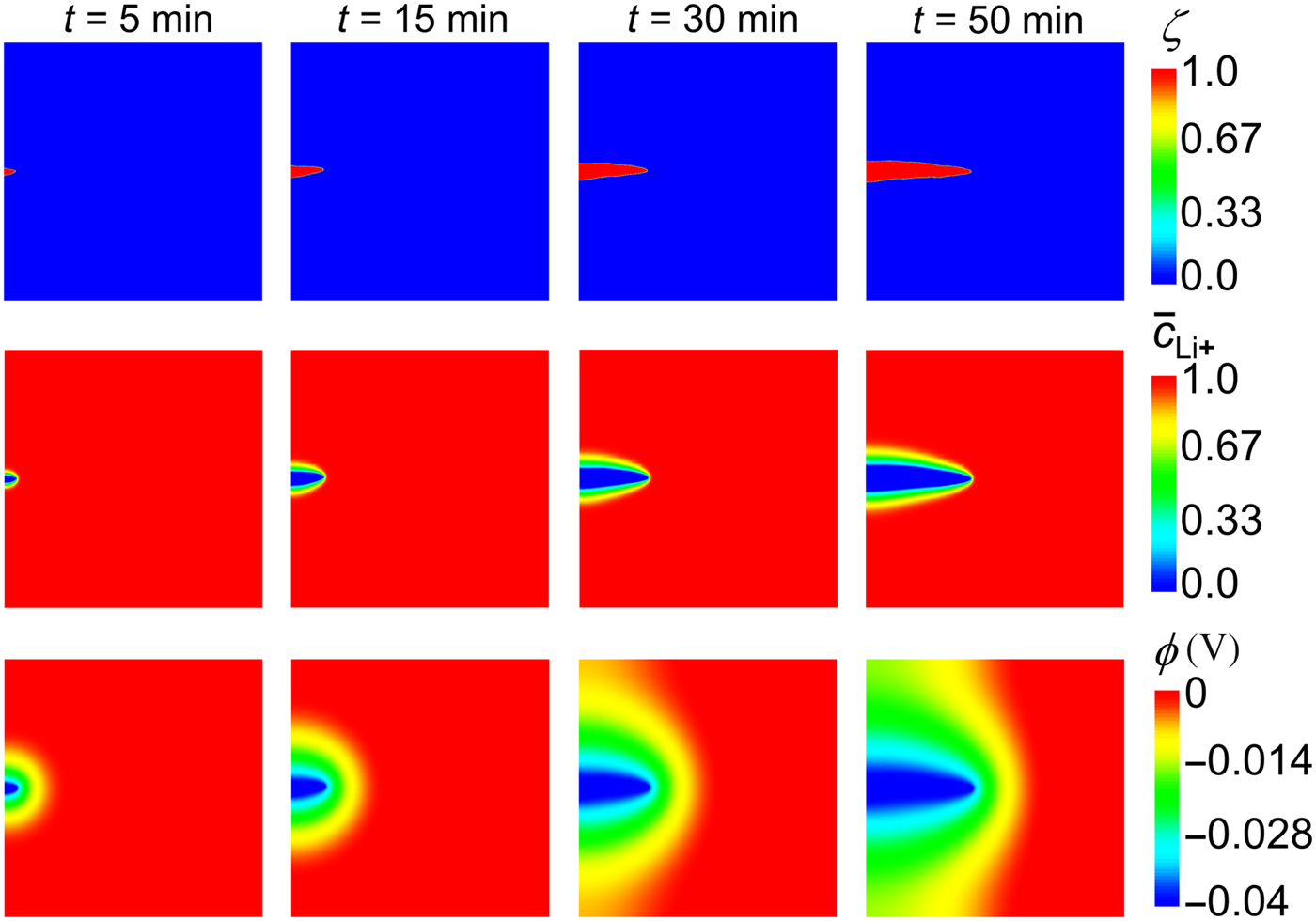
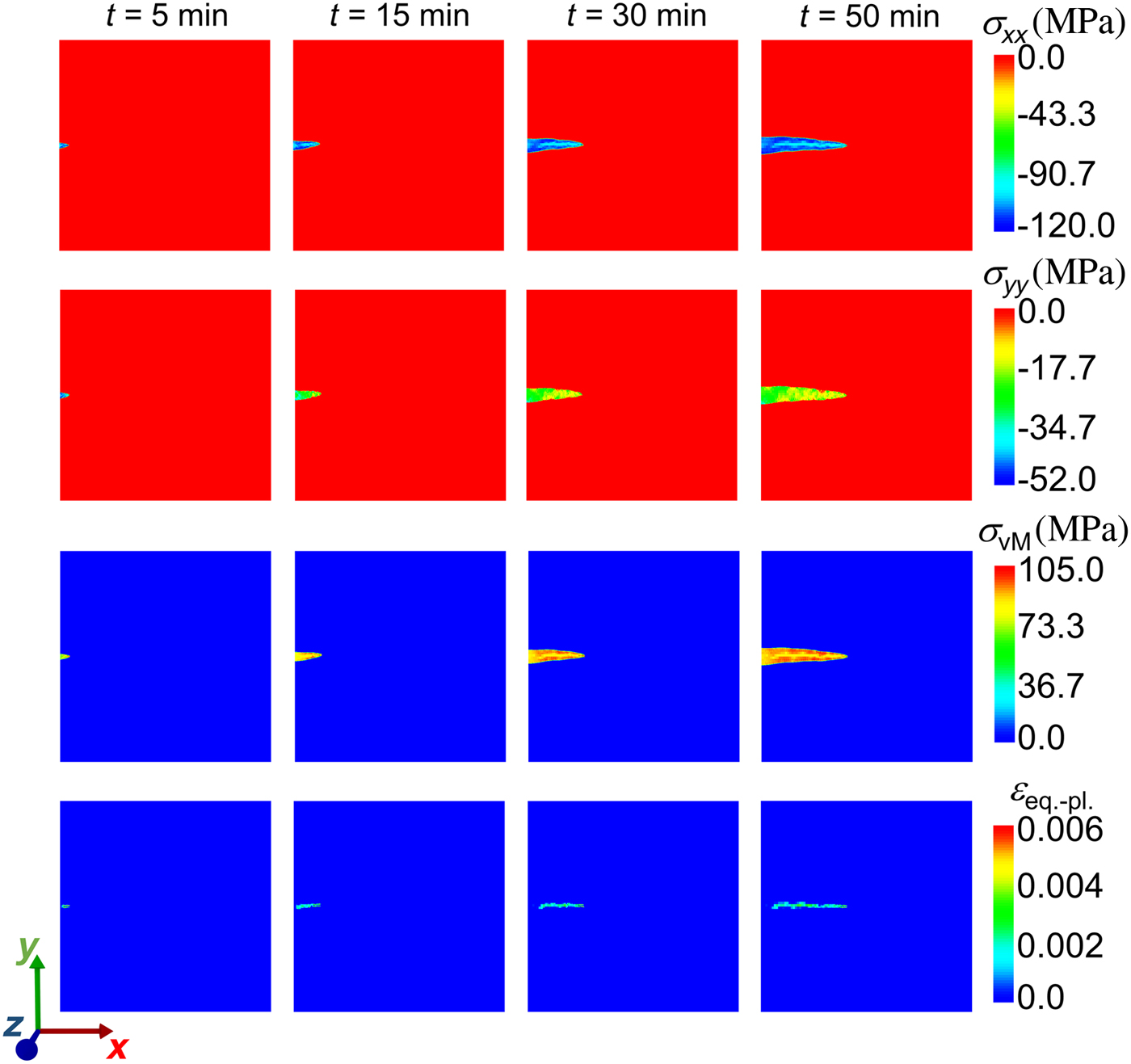
Following the general experimental principles, we set a concentration of Li-ions to one and the electrostatic potential to zero at the right boundary of the domain (see Fig. 1 second and third rows). At the other boundaries, zero-gradient boundary conditions are used. The 2D plain-strain assumption is made, meaning that out of plane strain vanishes (ε zz = 0, see Fig. 2).
The PFM results of a single Li filament growth. The solid Li filament evolution in time is shown in the first row; Li+ concentration development in the electrolyte is shown in the second row and the third row illustrates the evolution of the electric potential.

Mechanical properties evolution during a single Li filament growth. The first and second rows show the normal stress components (σ xx and σ yy); the third row demonstrates von Mises stress evolution in time and the fourth row illustrates the equivalent plastic strain.

Results and discussions
The aim of this work is to establish a correlation between the stress field and the mechanism of Li electrodeposition. Recently, Wang et al.[Reference Wang, Zeng, Hong, Xu, Yang, Wang, Duan, Tang and Jiang12] have reported that a significant compressive stress at the current collector is the main reason for the narrow/sharp filaments growth. In contrast, if a soft substrate at the current collector side is used, it relaxes the build-up of stresses leading to the smooth and non-dendritic electrodeposition. In order to test this hypothesis, we have designed the PFM to account for the hard and soft substrate, at which Li electrodeposits. For a deeper understanding of the influence of the stress field on the Li electrodeposition, we analyze different components of the stress and equivalent plastic strain in each subsection.
Material properties
Models such as the one employed in the present work necessarily involve a number of parameters. All model parameters are based on our previously reported results[Reference Yurkiv, Foroozan, Ramasubramanian, Shahbazian-Yassar and Mashayek16]. In particular, the modeling domain is set to be a square with sides equal to 5 µm, where the electrodeposition occurs at the left boundary and the right boundary is set to be the electrolyte. One M lithium hexafluorophosphate (LiPF6) dissolved in 1:1 (v/v) ethylene carbonate/dimethyl carbonate (EC/DMC) electrolyte is used. The Li+ concentration is normalized by the maximum concentration in the electrolyte ( $c_{{\rm L}{\rm i}^ +} ^{\max} $ = 1 × 10³ mol/m3) and the solid Li concentration (e.g., molar site density) is normalized by
 $c_{{\rm L}{\rm i}^{}}^{\max} $ = 7.64 × 10⁴ mol/m3. The mechanical model accounts for the elasto-plastic deformation of the Li solid phase. Following the work of Xu et al.[Reference Xu, Ahmad, Aryanfar, Viswanathan and Greer26], the anisotropic elastic constants of solid Li are C 11 = 14 GPa, C 12 = 11 GPa, and C 44 = 8.7 GPa. The yield strength of Li is 100 MPa, the hardening constant is 4.9 GPa and the hardening exponent is 0.4.[Reference Xu, Ahmad, Aryanfar, Viswanathan and Greer26] The Li+ diffusion coefficient is set to 4.0 × 10⁻¹⁰ m2/s, and the electrical conductivity of liquid and solid phases are 1.2 and 1 × 10⁷ S/m, respectively[Reference Valoen and Reimers27]. The surface energy of 0.6 J/m2[Reference Yamaki, Tobishima, Hayashi, Keiichi Saito, Nemoto and Arakawa2Reference Shin, Kannan and Kim8] is used throughout the calculations. The mode of the anisotropy is set to be 4 due to the cubic crystal structure of Li.
Single filament growth
We begin with a simple case of a single filament formation from the pre-existing protrusion at the surface. Figure 1 shows the results of a single filament growth together with the Li+ concentration change and electric potential development. As the initial condition, a small Li nucleus (20 nm radius of the semi-circle) is placed on the left boundary of the domain representing a typical roughness on the surface, where potentially Li filament growth tends to occur. Solid Li filament (upper panel of Fig. 1) unevenly grows from the left to the right boundary with enhanced electrodeposition at the root, where Li+ concentration (middle panel of Fig. 1) and the electric potential (last panel of Fig. 1) changes the most. Following the development of the electric potential and Li+ concentration in the electrolyte, it can be concluded that Li+ flux is governed by diffusion far from the filament, which switches to the mixed diffusion and electro-migration process close to the solid filament surface.[Reference Bai, Li, Brushett and Bazant4, Reference Yurkiv, Foroozan, Ramasubramanian, Shahbazian-Yassar and Mashayek16] This is due to a fact that close to the solid/liquid interface electrostatic potential gradient increases together with depletion of Li-ions. Such a result is anticipated because the charge transfer reaction, governed by the Butler–Volmer approach, occurs in the immediate narrow region near the solid/liquid interface.
We analyze the mechanical response of the single filament in Fig. 2, where the normal stress components in x- and y-planes are shown first, followed up by von Mises stress and the equivalent plastic strain. Significant stress develops under the inhomogeneous Li concentration field, resulting from the random ions delivery throughout the SEI and high anisotropic elastic medium of the solid filament. The von Mises stress development in Fig. 2 (third row) provides the indication of the regions with the highest probability of plastic yielding. The detailed analysis of mechanical behavior of the filament shows that the significant plastic yielding (fourth row) occurs in the later stages of the growth primarily through the center of the filament following the highest stress values in that region. To the best of our knowledge, such a mechanical response in Li electrodeposited phase has not been previously reported.
As mentioned above, three material parameters are needed to model the plastic response of Li, that is the yield strength (σ 0), the hardening constant (H), and the hardening exponent (m). These constants were reported in the prior literature[Reference Tariq, Ammigan, Hurh, Schultz, Liu and Shang29] and were used in the related studies[Reference Barai, Higa and Srinivasan14]. However, Xu et al. showed that the elasto-plastic behavior of Li is significantly size dependent[Reference Xu, Ahmad, Aryanfar, Viswanathan and Greer26], meaning that plastic parameters of micro-sized Li filaments are different than those at the centimeter scale. Specifically, the main discrepancy arises in the yield strength value, which was reported by Tariq et al.[Reference Tariq, Ammigan, Hurh, Schultz, Liu and Shang29] to be 0.65 MPa for centimeter-sized Li bar and about 100 MPa for 1.39 µm diameter Li bar. Such a significant difference in the yield strength changes plastic behavior of Li filament drastically since von Mises stress at each point of solid Li is much bigger than 0.65 MPa. This also may explain the experimentally observed Li penetration into the solid electrolyte with low Young's modulus and the plastic yielding of a polymer electrolyte in all-solid-state batteries.[Reference Barai, Higa and Srinivasan14]
Li electrodeposition on a hard substrate
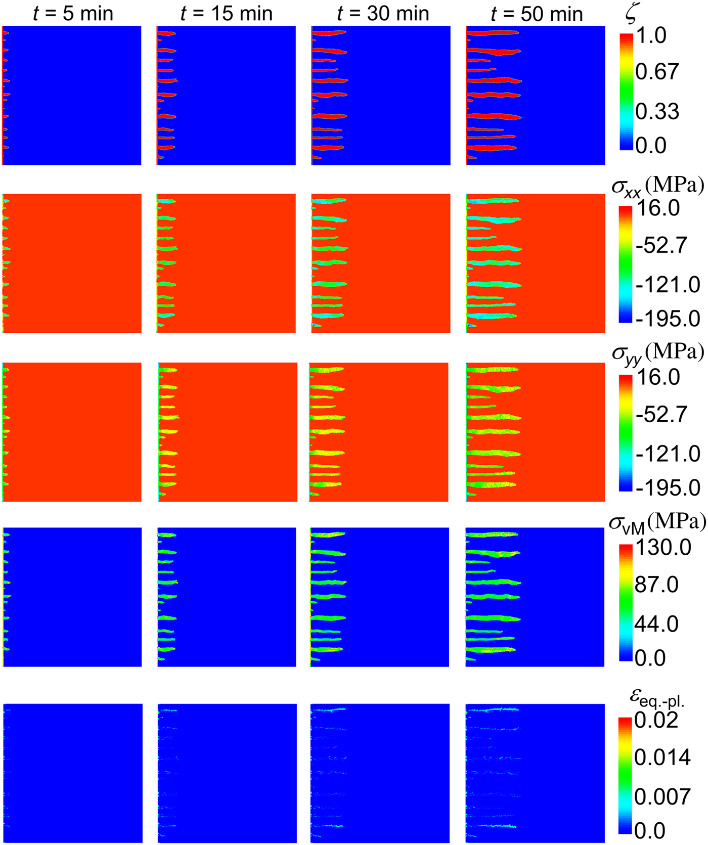
This section reports the PFM results considering a hard surface, where Li electrodeposition occurs. In the modeling framework, this is realized by setting displacement on the left boundary to zero (Dirichlet BC). Figure 3 shows the PFM results for such a constrained boundary. For clarity reasons, we only show the evolution of the Li solid phase and the development of mechanical properties. The electrodeposited Li phase consists of multiple narrow filaments of different sizes, which is consistent with the findings of Wang et al.[Reference Wang, Zeng, Hong, Xu, Yang, Wang, Duan, Tang and Jiang12]. They have experimentally reported that Li plating on the hard Cu surface results in sharp Li filaments of different sizes and tip shapes. In their work, they postulated that plating residual stress is a key component of the electrodeposition, and by having stress relaxation Li deposition could form uniformly. In the similar fashion to the previous section, Fig. 3 (second and third rows) shows profiles of the normal components of the stress tensor. These stresses are primarily compressive (negative values) and significantly anisotropic. In contrast, at the nodes between the filaments and the thin Li surface deposited on the left boundary (i.e., the current collector) tensile stress is developed reaching 16 MPa. In the origin of the Li filaments (i.e., the base at the left boundary), both stress components are significantly lower than in the rest of the plated Li, which indicates the stress-driven filaments formation during Li electrodeposition. Following the significant anisotropic stress development at the nodes, those regions could potentially experience damage through plastic deformation, which could lead to detachment from the base (“dead” Li). The amount of electric charge that flows in a cell over 50 min plating at 1 mA/cm2 equals to 3 Ccm2.
The PFM results of Li electrodeposition on a hard surface (left boundary constraint). The first row depicts the evolution of the Li solid phase; the second and third rows show different stress components (σ xx and σ yy); the fourth row demonstrates von Mises stress evolution in time and the fifth row illustrates the equivalent plastic strain.

The last row of Fig. 3 shows the equivalent plastic strain developed through the electrodeposited Li, using von Mises stress values reported in the fourth row. Although there is a plastic deformation of filaments, it does not influence the growth rate significantly. However, this situation may change drastically in the presence of the separator or a barrier protective layer as reported for the polymer-based electrolytes.[Reference Barai, Higa and Srinivasan14, Reference Ferrese and Newman30] Ferrese and Newman[Reference Ferrese and Newman30] and Barai et al.[Reference Barai, Higa and Srinivasan14] have reported that a uniform Li deposition can occur due to a plastic deformation of Li metal under the influence of a stiff separator.
Li electrodeposition on a soft substrate
Next, we present the simulation results of the Li electrodeposition on a soft substrate. The modeling here is motivated by the fact that the usage of the soft substrate can partially prevent the undesired sharp filaments formation, and in combination with other protective strategies[Reference Foroozan, Soto, Yurkiv, Sharifi-Asl, Deivanayagam, Huang, Rojaee, Mashayek, Balbuena and Shahbazian-Yassar11], it could ensure safe and long-lasting battery operation. In the model, the soft substrate is realized by allowing the domain to expand freely on the left boundary; however, no Li flux is permitted through the boundary (zero flux BC). Figure 4 shows the PFM results of the Li electrodeposition considering the soft substrate. The same as in the previous section, this figure demonstrates the growth of the solid phase (first row), different normal components of the Cauchy stress tensor (second and third rows), the von Mises stress development (fourth row), and the equivalent plastic strain (last row). The first row in Fig. 4 demonstrates that the sharp Li filaments are not formed; instead, there is a uniform Li distribution at the earlier stages of electrodeposition with further appearances of smooth bumps at the later stages. The normal components of stresses are primarily compressive, but there is a small region of tensile stresses at the regions with high curvature, where Li bumps start to form. In these places, a significant plastic yielding occurs, which may lead to the fracture or crack formation.
The PFM results of Li electrodeposition on a soft substrate. The first row depicts the evolution of Li solid phase; the second and third rows show elastic components (σ xx and σ yy); the fourth row illustrates the von Mises stress development and the fifth row depicts equivalent plastic strain.

Influence of stress on Li electrodeposition
These findings unambiguously demonstrate that the usage of the soft substrate can potentially help to prevent undesired sharp filaments formation. Although these PFM results demonstrate that the soft substrate approach may lead to the desired uniform electrodeposition, they need to be treated with caution. The high-stress development and a big contact surface at the interface with the liquid electrolyte suggest that the Li surface could create a bigger force on the separator or protective interface (e.g., graphene oxide[Reference Foroozan, Soto, Yurkiv, Sharifi-Asl, Deivanayagam, Huang, Rojaee, Mashayek, Balbuena and Shahbazian-Yassar11]), which may lead to its breakdown.
In both hard and soft substrate cases, the stress field shows significant anisotropy within the surface and the filaments. It would be of interest to know the portion of the anisotropy caused by the SEI governing the random electrodeposition of Li and anisotropic elastic properties of Li (A = 2C 44/(C 11 + C 22) = 8.52). Depending upon the type of the SEI, Li+ diffusion through it is undoubtedly anisotropic, which would lead to a very random electrodeposition with significant enhancement in one place and moderate in the other. Considering the current incomplete stage of knowledge about the structure of the SEI and its properties, there is no possibility to estimate Li+ delivery to the two-phase boundary for electrochemical reaction precisely. However, it is certain that a thick SEI layer (mechanically soft) will lead to the Li anisotropic elastic properties control of the filaments growth. On the other side for a thin SEI layer (mechanically stiff), anisotropic delivery of Li-ion through that layer will define the growth of the filaments.
As discussed above, the plastic yielding significantly depends on the size of the electrodeposited Li. The amount and maximum equivalent plastic strain shown in Figs 3 and 4 should not be taken as a precise optimal result. Rather, this result serves as a demonstration of the region, where plastic flow could potentially occur and serves to facilitate the discussion of competing elastic and plastic deformations of filaments. However, these findings can be used to evaluate the design and operational alternatives for the particular barrier protective layer in LMBs.
The other valuable point is the correlation between the metal conductivity and the stress field. In particular, it is known that the electrochemical potential of the solid phase depends on the stress field. If the stress field has a detrimental effect on the electrochemical potential of solid Li, this consequently will change its conductivity. However, in the case of a significant plastic deformation of the electrode, elastic energy density will be significantly altered, which will influence the conductivity. Moreover, under an additional external pressure on the solid Li electrodeposits, caused by for example separator or the barrier protective layer, the relation between the conductivity and the stress field leads to non-intuitive behavior, where many physico-electrochemical and mechanical factors should be taken into account.
Summary and conclusions
A 2D computational model is applied to investigate the Li electroplating in the Li-metal battery configuration. The model predicts ion concentration, electrical potential variation as well as elastic-plastic properties of the electrodeposited Li. Ion transport through the electrolyte and potential distribution in the domain are modeled using the Nernst–Planck–Poisson's theory. The Butler–Volmer equation is used to describe the charge-transport reaction. Elastic properties of electrodeposited Li are modeled employing the Cauchy–Green deformation theory using the elastic stiffness tensor of linear elastic transversely isotropic material. The plastic deformation is evaluated based upon the von Mises stress criteria. The present study concentrates primarily on the investigation of the stress on the Li electrodeposition and not specifically on the development of the dendrite prevention strategies. However, by considering several examples some interesting observations can be deduced, which can help in the development of such protecting strategies.
The approach in the present work begins with the investigation of the single filament formation to demonstrate the capability of the model. This is followed by the detailed analysis of Li electrodeposition considering hard and soft substrates, on which the Li deposition occurs. Also, deleterious stress-induced sharp filaments formation is discussed. The important new aspect presented in this work is the inclusion of the plastic energy density in the total energy functional, allowing to monitor plastic yielding of Li electrodeposits. The growth induced stresses are very high, leading to the plastic deformation of Li. The present PFM results reveal that stress is particularly high in the vicinity of notch-like features on the Li surface. In contrast, significantly lower stresses are observed in the filaments. In general, the usage of the soft substrate is more beneficial comparing with the hard one, since it can promote a more uniform Li electrodeposition. However, the existence of a dense layer could potentially cause a higher pressure on the separator, which could lead to the undesired mechanical effects. Thus, the mechanical properties of the current collector should be chosen judiciously.
It should be also noted that, although the results reported here are based on quantitative simulations, they should be utilized to find qualitative trends. Particularly, individual filament size and shape are always random throughout all electrodeposition process. The SEI thickness and properties are also random (uncontrollable) along the filaments. Thus, the simulation cannot produce a particular cell appropriate result, and should be rather treated to distinguish trends.
The results also emphasize the importance of considering several electrodeposition mechanisms simultaneously, when determining protecting strategies against undesired sharp filaments formation. Although the present study does not consider any protective mechanisms, it is clear that reasonable variation of several filaments growth mechanisms would provide an adequate solution for protecting Li-metal anode towards long-lasting and efficient LMB's operation.
Acknowledgments
The MOOSE team is gratefully acknowledged for helping in the development of the model and many insightful discussions on the topic presented in this work. R. Shahbazian-Yassar acknowledges the financial support from the National Science Foundation (Award No. 1620901). The present computations were performed on the High-Performance Computing Clusters Extreme and Dragon at the University of Illinois at Chicago.