NOMENCLATURE
- AC
-
aerodynamic damping matrix
- AK
-
aerodynamic stiffness matrix
- AR
-
wing aspect ratio
- g
-
acceleration of gravity
- b
-
wingspan
- C
-
damping matrix
- CL
-
lift coefficient
- C L α
-
lift coefficient slope
- c
-
wing chord
- EI 1
-
flap-bending stiffness
- EI 2
-
chord-bending stiffness
- F
-
force
- f
-
natural frequency
- GJ
-
torsional stiffness
- I 2/I 1
-
inertia ratio
- K
-
stiffness matrix
- M
-
mass matrix
- q
-
system degrees of freedom
-
 $\bar{q}$
-
amplitudes of the disturbed system degrees of freedom
- q 0
-
static aeroelastically deformed state
- S
-
wing area
- s
-
complex frequency
- t
-
time
- uz
-
vertical displacement

Greek Symbol
- α
-
angle-of-attack
- θ x
-
bending rotation angle
- θ y
-
angle of twist
1.0 INTRODUCTION
The search for more efficient aircraft designs for both economical and environmental gains has lead to a renewed interest in high aspect-ratio wings. Configurations with high aspect-ratio wings have the advantage of reducing the induced drag resulting in higher lift-to-drag ratios and longer range(Reference Abbott and Doenhoff2). According to Abbas et al(Reference Abbas, de Vicente and Valero1), the induced drag in a large transport aircraft is about 43% of the overall drag during cruise, thus representing a great improvement in flight efficiency if reduced. Different approaches can be applied to increase wing Aspect Ratio (AR) for conventional designs such as increasing wingspan or reducing wing chord. Also unconventional aircraft designs such as the Joined-Wing(Reference Cavallaro and Demasi11,Reference Wolkovitch39) , the Strut-Braced-Wing(Reference Carrier, Atinault, Dequand, Hantrais-Gervois, Liauzun, Paluch, Rodde and Toussaint10,Reference Cavallaro and Demasi11) , the Box-Wing(Reference Cavallaro and Demasi11,Reference Frediani, Cipolla and Rizzo19) and the C-Wing(Reference Demasi, Monegato, Dipace and Cavallaro14,Reference Demasi, Monegato, Rizzo, Cavallaro and Dipace15,Reference McMasters and Kroo26) also have the goal of reducing the induced drag by means of increasing the wing aspect ratio.
Despite the several aforementioned aerodynamic benefits, there are some drawbacks from the structural perspective: the wing-root bending moment increases due to the wingspan increase, and higher flexibility is observed due to the slender design. Thus, the design of a high aspect-ratio wing is a truly multidisciplinary task requiring an aeroelastic evaluation. Furthermore, there are also limitations to the allowable span in airport terminals and maintenance facilities imposing a span constraint to the design and requiring the development of wing-tip devices. This explains the fact that current commercial aircraft present relatively low aspect-ratio wings.
The effect of the increase of structural flexibility, which may lead the wing to undergo larger deformation under normal operating conditions is studied here. Large wing deformations, if large enough, lead to the appearance of geometrical non-linearities, which might alter the wing dynamic behaviour and consequently can cause aeroelastic instabilities(Reference Harmin and Cooper20,Reference Patil, Hodges and Cesnik32,Reference Patil, Hodges and Cesnik33) . Therefore, it is essential to assess the influence of nonlinearities on the aeroelastic behavior, particularly in terms of flutter and divergence phenomena.
Several numerical investigations were carried out over the last few decades using low-/medium-fidelity models to study the non-linear aeroelasticity of high aspect-ratio wings. The aerodynamics are normally modeled using a panel code (usually the Doublet-Lattice Method)(Reference Patil and Hodges30) or a 2D unsteady aerodynamic model capable of predicting flow separation(Reference Arena, Lacarbonara and Marzocca5,Reference Dowell and Tang16) . The structures are usually modeled as beams using analytical(Reference Arena, Lacarbonara and Marzocca5,Reference Dowell and Tang16,Reference Patil and Hodges30) or finite element models(Reference Kampchen, Dafnis, Reimerdes, Britten and Ballmann23). Some computational frameworks were specially developed to study the coupling of flight mechanics with non-linear aeroelasticity of very flexible high aspect-ratio wings (namely the high-altitude, long-endurance aircraft) such as ASWING(Reference Drela17), NATASHA(Reference Patil29,Reference Patil and Hodges31) , UM/NAST(Reference Cesnik and Brown12,Reference Cesnik and Su13,Reference Shearer and Cesnik34) , NANSI(Reference Wang, Chen, Liu and Mook38) and SHARP(Reference Murua27,Reference Murua, Palacios and Graham28) . Nonetheless, just a few experimental studies are available, which consist of simple planar rectangular wings with constant cross-sectional properties at low subsonic speeds, with highly flexible structures projected to deform substantially(Reference Dunn and Dugundji18,Reference Kampchen, Dafnis, Reimerdes, Britten and Ballmann23) in order to find Limit Cycle Oscillation (LCO)(Reference Tang and Dowell36) or study gust response(Reference Tang and Dowell37).
For this work, an in-house non-linear aeroelastic framework(Reference Afonso, Leal, Vale, Oliveira, Lau and Suleman3,Reference Suleman, Afonso, Vale, Oliveira and Lau35) with the capability of analysing the aeroelastic behaviour of very flexible low-speed aircraft was used.
Despite a large number of reported studies, just a few of high aspect-ratio wings studies taking into account geometric nonlinearities have been reported to assess the differences between linear and non-linear static aeroelastic analyses of high aspect-ratio wings. Here, several design parameters are compared: displacements, lift and twist distributions, natural frequencies, flutter and divergence speeds. In the end, wings with varying aspect ratios were analysed, and the influence of the aspect ratio and the geometric non-linearities on the aeroelastic performance (in terms of flutter and divergence speeds) were evaluated.
2.0 THEORETICAL FORMULATION
The aeroelastic problem is traditionally presented as a system of second-order differential equations:
 $$\begin{equation}
\left[M\right]\lbrace \ddot{q}\rbrace + \left[C\right]\lbrace \dot{q}\rbrace + \left[K\right]\lbrace q\rbrace = \lbrace F\rbrace ,
\end{equation}$$
where [M], [C], [K] are the mass, damping and stiffness matrices of the system, respectively, {F} is the vector of applied loads, and {q} the system degrees of freedom.
The aeroelastic phenomena that can result from the interaction of these forces are usually put into one of two categories: static or dynamic. Static aeroelastic phenomena only takes into account the interaction between aerodynamic and elastic forces, i.e. it is time independent. No inertial loads are considered and the system reduces to:
 $$\begin{equation}
\left[K\right]\lbrace q\rbrace = \lbrace F\rbrace
\end{equation}$$
The load vector in the static aeroelastic problem is the sum of the aerodynamic and gravity loads:
 $$\begin{equation}
\lbrace F\rbrace = \left[M\right]\lbrace g\rbrace + \left[A_K\right]\lbrace q\rbrace ,
\end{equation}$$
where {g} is the gravity acceleration vector, and [AK ] is the aerodynamic stiffness matrix. The aerodynamic load depends on the system degrees of freedom, as shown in the second term of the second member in Equation (3). To compute nonlinear displacements for a known constant load, the Newton-Raphson algorithm is generally used. However, once the aerodynamic load is not independent from the structural displacements (i.e. the system degrees of freedom), it will consequently lead to the presence of aerodynamic non-linearity. Usually the aerodynamic and structural models are solved separately and do not have the same degrees of freedom; in fact, the structural meshes are in general more coarse than the aerodynamic ones(Reference Ballmann6). Therefore, it is common practice to use a Fluid-Structure Interaction (FSI) algorithm to transfer the loads from the aerodynamic mesh to the structural mesh and the structural displacements to the aerodynamic mesh(Reference Ballmann6). FSI algorithms use iterative methods to reach convergence. A situation arbitrarily close to the equilibrium state is thus obtained:
 $$\begin{equation}
\left[K\right]\lbrace q\rbrace - \left[M\right]\lbrace g\rbrace - \left[A_K\right]\lbrace q\rbrace \approx \lbrace 0\rbrace
\end{equation}$$
Aeroelastic divergence occurs when the airspeed is such that this equilibrium is no longer attainable and the system deformation tends to the infinity. The speed at which this phenomena occurs is computed using NASTRAN™.
For dynamic aeroelastic phenomena, all three interaction forces are considered: aerodynamic, elastic and inertial. The flutter instability is usually the most critical dynamic aeroelastic phenomenon that can afflict an aircraft, and the most difficult to predict(Reference Wright and Cooper40). Wing flutter is a dynamic aeroelastic instability that, in its classic form, results from the coupling of two vibration modes, most commonly a wing-bending mode with a wing torsion mode. The frequency of this two vibration modes become increasingly closer with the dynamic pressure (wind speed) increase. This unstable self-excited vibration extracts energy from air stream leading to a catastrophic structural failure(Reference Wright and Cooper40).
The dynamic problem can be solved by using either a time domain approach or a frequency domain approach. For this work, NASTRAN™ was used to determine flutter, and thus a frequency domain approach was followed. Assuming that the system is statically balanced with {q 0} corresponding to the static aeroelastically deformed state, the total deformation for the aeroelastic dynamic problem is given by:
 $$\begin{equation}
\lbrace q\rbrace = \lbrace q_0\rbrace + \lbrace \bar{q}\rbrace e^{s t},
\end{equation}$$
where
 $\lbrace \bar{q}\rbrace e^{s t}$
term in Equation (5) corresponds to the disturbances in the system degrees of freedom, which are given as harmonic oscillations at specific damped frequencies. Considering this assumption, the equilibrium equation of the aeroelastic problem can be given by:
 $$\begin{equation}
s^2\left[M\right]\lbrace \bar{q}\rbrace e^{s t} - s\left[A_C\right]\lbrace \bar{q}\rbrace e^{s t} + \left(\left[K\right] - \left[A_K\right]\right)\lbrace \bar{q}\rbrace e^{s t} + \left(\left[K\right] - \left[A_K\right]\right)\lbrace q_0\rbrace - \left[M\right]\lbrace g\rbrace = \lbrace 0\rbrace,
\end{equation}$$
where the aerodynamic stiffness ([AK
]) and damping ([AC
]) matrices present a non-linear dependence on the complex frequency s,
 $\lbrace \bar{q}\rbrace$
and {q
0} denote the vector of the amplitudes of the disturbed system degrees of freedom and static aeroelastically deformed state, respectively. To compute the flutter speed, it is assumed that the mass [M], damping [C] and stiffness [K] matrices are constant and set equal to the ones attained from the converged aeroelastic static equilibrium state (Equation (4)). This assumption also results in a cancellation of the last two terms on the left-hand side of Equation (6) i.e. ([K] − [AK
]){q
0} − [M]{g} = {0}. The structural damping [C] can be neglected due to the more substantial contribution of the aerodynamic damping component ([AC
]). Thus, we obtain:
 $$\begin{equation}
\left[ s^{2}\left[M\right] - s\left[A_{C}\right] + \left[K\right] - \left[A_{K}\right] \right] \lbrace \bar{q}\rbrace = \lbrace 0\rbrace
\end{equation}$$
At this point, there is no information about the system’s damped frequencies. They must be iteratively determined and one of the most accurate and most popular methods to do so is the p-k method(Reference Hodges and Pierce21). Therefore, the hard part of the procedure is determining the aerodynamic stiffness matrix for a given equilibrium condition, and this is usually done by applying linearised potential equations from theories such as the popular Doublet-Lattice Method (DLM). This method is integrated in Finite Element Analysis (FEA) programs such as NASTRAN
 $^{\textrm {TM}}$
. Aerodynamic finite element models using the DLM consist of planar lifting surfaces divided in columns and rows of trapezoidal elements with their lateral edges lying parallel to flow direction. This configuration means that they cannot represent aerodynamic features such as aerofoil incidence, camber and thickness. Even though these features are important in static problems, suppressing them in dynamic aeroelastic ones is not such an inaccurate simplification if the aerofoils are thin and flying at low angles of attack. The theory behind this method is presented in detail in the literature(Reference Albano and Rodden4).
3.0 DEVELOPED FRAMEWORK/METHODOLOGY
With the goal of integrating the capabilities of analysing morphing solutions and novel configurations in a multidisciplinary design optimization environment, a computational framework was developed in the scope of the EU FP7 NOVEMOR project. To expand the potentialities of this tool in preliminary aircraft design, an aeroelastic module was devised with the possibilities of running linear and non-linear static aeroelastic analyses(Reference Afonso, Leal, Vale, Oliveira, Lau and Suleman3,Reference Suleman, Afonso, Vale, Oliveira and Lau35) . This framework was designed to be both modular and versatile. For the studies performed here, geometric, aerodynamic, structural and aeroelastic modules were employed.
Both aerodynamic and structural models are of low/medium fidelity. The aerodynamic model consists of a 3D panel method formulation(Reference Katz and Plotkin24) that takes into account the Prandtl-Glauert compressibility correction(Reference Bertin8) and estimates the viscous drag for each panel in the model (using the flat plate zero-pressure gradient friction drag-based calculation(Reference Mason25)). The stiffness and mass distributions along the wingspan are firstly determined by calculating the inertia properties of the spanwise wing cross-section, and then condensed in a 3D beam model(Reference Wright and Cooper40) to form the structural model. A finite element mesh is generated based on the condensed beam model using 3D Euler-Bernoulli beam elements(Reference Zienkiewicz41) to compute linear and non-linear analyses.
Both geometric and stress-stiffening non-linearities can be considered in the structural model, while the aerodynamic non-linearities are strictly geometrical, in the sense that they are only caused by the structural displacement.
For the static aeroelastic calculations, the aeroelastic module is employed, which calculates the linear or non-linear static equilibrium using a monolithic(Reference Hulshoff22) loosely coupled(Reference Bazilevs, Takizawa and Tezduyar7) algorithm. This FSI routine can be considered: (1) monolithic in the sense that the solution only advances in a load step after both aerodynamic and structural solutions are converged, and (2) loosely-coupled because the two solvers are first solved individually and then coupled until convergence is achieved. The aeroelastic module is responsible for transferring the loads from the aerodynamic panels to the structure and transferring the structural displacements to the aerodynamic panels. Normally, to accurately model the fluid dynamics a detailed mesh is required, while for the structural dynamics a coarse mesh suffices(Reference Ballmann6). This leads to different mesh sizes and thus requiring a proper load and displacement transfer method.
The FSI routine is an iterative process that converges when equilibrium is reached, i.e. when both displacements and loads have converged. The aerodynamic model is re-meshed at each equilibrium iteration. To help reaching convergence, a few features were implemented in the developed framework: first, in the case where convergence has not been reached, the aeroelastic module performs a bisection of the load and displacement and starts at the previous equilibrium state (corresponding to the undeformed state if the bisection is done in the first iteration); second, one can start with just a fraction of the total load meant to be transferred to the structure.
The aeroelastic flutter boundary calculation is performed at the equilibrium state (similar to what was done in other works(Reference Afonso, Leal, Vale, Oliveira, Lau and Suleman3,Reference Cesnik and Su13,Reference Dowell and Tang16,Reference Patil, Hodges and Cesnik33) ) using the p-k method and the updated stiffness and mass matrices obtained from the non-linear equilibrium. If a linear structural analysis is chosen instead in the aeroelastic module, the flutter speed calculation is performed using the undeformed stiffness and mass matrices. In both cases [AK ] and [AC ] matrices are affected by the displaced geometry.
NASTRAN™ was used to calculate the flutter and divergence speeds. In this methodology, only geometric non-linearities are transmitted to the NASTRAN™ model through the generation of a model with the deformed shape. The flutter and divergence speeds are computed for the static aeroelastic linear or non-linear equilibrium state.
4.0 WING MODEL
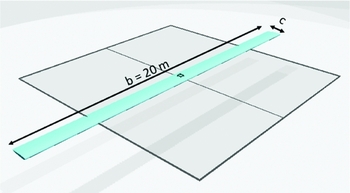
A rectangular wing model similar to the experimental wing models found in the literature(Reference Kampchen, Dafnis, Reimerdes, Britten and Ballmann23,Reference Tang and Dowell36) was devised. This model (Fig. 1) consists of a rectangular NACA 0012 wing made of aluminum (properties in Table 1) with a constant wingspan (b) of 20 m and a variable chord (c).
Basic wing model configuration.

Isotropic aluminum properties

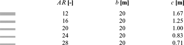
Since one of the main objectives of this work is to evaluate the influence of wing Aspect Ratio (AR) on the aeroelastic performance of the wing, five different aspect-ratio wings were considered, as can be seen in Table 2. The basic wing configuration is the AR = 20 wing model.
Main characteristic of the five different wing aspect-ratio configurations

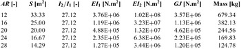
As mentioned, the wingspan is kept unchanged and only the wing chord is altered to accomplish the desired aspect ratio. Note that by reducing the wing chord both bending stiffnesses (EI 1 and EI 2) and the torsional stiffness (GJ) diminish; however, the inertia ratio (I 2/I 1) remains the same because the same aerofoil is used and the same thickness ratio (i.e. the same wing-box layout) is maintained. Consequently, both mass and wing area (S) also reduce as the wing chord reduces, and thus the displacements for the same flight condition (speed, altitude and angle-of-attack) are predicted to be higher. The main properties of the five wings considered are summarised in Table 3.
Main characteristic of the five different wing aspect-ratio configurations

The same flight condition was assumed for all the cases: constant airspeed of 40 m/s; sea level altitude conditions; and angle-of-attack ranging from − 4° to 10°. Airspeed and altitude were chosen such that the flow remains low subsonic and incompressible for which the Panel Method predicts more accurately the aerodynamic forces. If higher speeds were considered, the Prandtl-Glauert should be used. For transonic speeds with shock waves, this model is not applicable. The 3D effects on the lift distribution are predicted to be small since the wing aspect ratio values are relatively high. Wing self-weight was also included in the calculations due to the high structural flexibility presented.
Even though the wing models are different, the same aerodynamic and structural meshes defined for the aspect-ratio 20 wing were used in all the analyses herein carried out. This assumption was made based on the fact that very small variations were found when refining the meshes for the different wing models. The structural mesh is composed of 60 non-linear beam elements uniformly distributed along the wingspan, while the aerodynamic mesh was built using cosine distributions considering 30 spanwise divisions and 40 chordwise divisions (for each of the chord strips, a wake panel element of 100 chords length was defined in the chord direction).
5.0 LINEAR VS NON-LINEAR STUDY
This study consists in evaluating the geometric non-linear effects on the wing deformed state and flutter speed. Only the higher aspect-ratio wings described in the previous section were considered for this study: 20, 24, and 28. The influence of the wing aspect ratio on the aeroelastic performance is analysed in detail in Section 6.
All the aeroelastic equilibrium states (linear and non-linear) were computed by using the in-house aeroelastic framework. In order to compare both linear and non-linear analyses, the following metrics are investigated: lift coefficient, vertical-tip displacement, spanwise lift and twist distributions, deformed wing shape, and flutter speed.
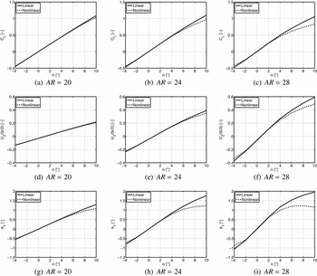
From Fig. 2, one can notice that non-linear effects become more evident with the wing aspect-ratio increase, for the same flight conditions (speed, altitude and angle-of-attack). This fact is not caused by the increase of the aspect ratio per se, but it is rather caused by the associated reductions on wing mass and both bending and torsional stiffnesses, which make the wing more flexible. In a previous work by the authors(Reference Afonso, Leal, Vale, Oliveira, Lau and Suleman3), the stiffness parameters were observed to have a considerable impact on the flutter speed for the wing with aspect ratio of 20 (the same used here), especially the torsional stiffness.
Lift coefficient (top row), dimensionless vertical-tip displacement (centre row) and tip twist angle (bottom row) variations with angle-of-attack (α) and Aspect Ratio (AR).

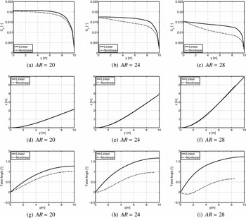
If one looks at Figs 2(a)–(c), which show the CL variation with the angle-of-attack (α) for the three aspect-ratio wings, it is observable: a decrease of linear dependence of CL with α. As a consequence of weakening the wing structure (reduction of the torsional stiffness and bending stiffness), for the same condition (speed, altitude and angle-of-attack), the displacements are higher (vertical displacement and twist/incidence angle, as can be seen in Figs 2(d)–(i)) changing the lift distribution as illustrated in Figs 3(a)–(c). This effect is observed even for the linear solution. With the non-linear solver this effect becomes more evident, and the deviation from the linear aeroelastic equilibrium state increases as the aspect ratio increases.
Spanwise lift coefficient distribution (top row), wing deformed shape (centre row) and spanwise incidence angle distribution (bottom row) variations with Aspect Ratio (AR) for an angle-of-attack of 10°.

The change of the spanwise dimensionless lift distribution with the aspect ratio caused by the significant wing deformation is shown in Figs 3(a)–(c) for the 10° of angle-of-attack case (where the wings suffer higher deformations). The modification of the spanwise lift distribution is due to the increase on bending rotation of the wing (θ X ) related to the vertical displacement distribution (see Figs 3(d)–(f)) and the change in the incidence of the aerofoils (see Figs 3(g)–(i)) producing the observed different lift distribution. This change is very perceptible even for the linear solution. The difference between the linear and non-linear spanwise dimensionless lift distribution becomes more evident as the displacement increases. This difference between linear and non-linear spanwise dimensionless lift distributions is caused mainly by the variation in spanwise incidence angle distribution (very clear in Figs 3(g)–(i)) and in a smaller scale by the artificial stretching effect on the span, given by the linear aeroelastic equilibrium solution (visible in Figs 3(d)–(f)).
The differences between linear and nonlinear aeroelastic equilibrium solutions for the deformed wing shape are not so evident as the previous observations. Even for the 10° of angle-of-attack case depicted in Figs 3(d)–(f), the wing linear deformed curve lies on the non-linear deformed curve, and the shortening effect on the wing tip is the only perceptible difference in the wing deformed shape.
For these wings, the same flutter mechanism was found, consisting of a coupling between the first torsion mode and the third flap-bending mode. This behaviour is explained in Section 6.
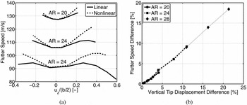
The discrepancy between linear and non-linear solutions is very noticeable in the flutter speed plot (Fig. 4(a)), in which even for a stiffer wing (AR = 20), one can observe these differences. The linear calculation result of the flutter speed is lower when compared with the non-linear solutions: hence, the importance of taking into account the deformed state when computing the flutter speed. For high angle-of-attack conditions, the higher displacements obtained for the wing with higher aspect ratio cause an inflection on the trend of flutter speed increase with tip displacement.
Flutter speed as a function of dimensionless-tip displacement variations with Aspect Ratio (AR) (a); and flutter speed difference (relative difference between linear and non-linear) as a function of vertical-tip displacement difference (relative difference between linear and non-linear) (b).

If one plots the flutter speed difference (between the linear and non-linear solutions) as a function of the vertical-tip displacement difference (between the linear and non-linear solutions), one can find in Fig. 4(b) that regardless of the wing aspect ratio and the magnitude of the displacement, there is a nearly linear dependence between those two factors. A very small difference between slopes is observed in Fig. 4(b) for the three aspect-ratio wings. From Fig. 4(b), one can also observe that the flutter speed difference increases as the vertical-tip displacement difference increases.
6.0 WING ASPECT-RATIO STUDY
In this study, the main aim is to evaluate the influence of aspect ratio on the aeroelastic behavior of high aspect-ratio wings. Thus, the five different wing aspect ratios described earlier were considered: 12, 16, 20, 24 and 28.
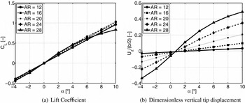
Figure 5(a) shows the CL variation with angle-of-attack for the five different aspect-ratio wings. It can be seen that as the aspect ratio increases, the range of linear dependence of CL with α is reduced. This is due to the higher vertical displacements caused by a reduction on the bending stiffness (EI) on both flap and chordFootnote 1 planes; and due to the higher incidence angles caused by torsional stiffness decrease (as noticed in Section 5), when the wing chord decreases and thus aspect ratio increases. The increase on the wing aspect ratio causes an increase in C L α and a non-linear deformation, as can be observed in Fig. 5(b), which shows the dimensionless vertical-tip displacement variation with α for the five wings. One can see that the higher aspect-ratio values cause higher displacements for the same α, which is caused by the decrease on the bending stiffness and torsional stiffness as chord decreases and aspect- ratio increases.
Lift coefficient and dimensionless vertical-tip displacement variations with angle-of-attack (α) and Aspect Ratio (AR).

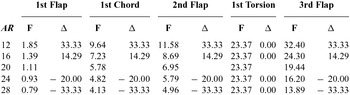
Before evaluating the effects of increasing the wing aspect ratio, the first five undeformed modes shapes were identified and are presented in Table 4 for the five different configurations. One can notice that the natural frequencies decrease as the aspect ratio increases, except on the torsion natural frequency, which remains constant because the effects of decreasing torsional rigidity and reducing the mass moment of inertia cancel the natural frequency value. The natural frequencies associated to the flap- and chord-bending modes decrease because both bending stiffnesses decrease as well. Both the flap- and chord-bending natural frequencies decrease with the same percentage Δ relatively to the AR = 20 configuration, as can be observed on the Δ columns of Table 4.
First five natural (undeformed) frequencies (F) in Hz for the five different aspect-ratio wings. Δ represents the difference of the natural frequency (in percentage), relative to the
 ${\bm AR } {\bf = 20}$
configuration
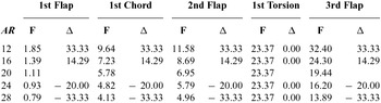
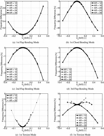
Figure 6 depicts the first five natural frequencies’ variation relative to the corresponding undeformed natural frequencies with dimensionless-tip displacement. For the flap-bending modes (Figs 6(a), (c) and (d)), the difference between undeformed and deformed natural frequencies stays below 7%. The magnitude of the differences increases as the frequency is higher, and for the second and third flap-bending modes, it increases with the magnitude of the dimensionless-tip displacement. For the first flap-bending modes (Fig. 6(a)), the natural frequencies increase with the dimensionless-tip displacement in contrast with the second (Fig. 6(c)) and third (Fig. 6(d)) flap-bending modes, but the magnitude of the differences is very low and, therefore, not significant.
Evolution of the natural frequencies with the wing deformation in detail.

For the chord-bending mode, Fig. 6(b) shows the results of frequency difference variation with the dimensionless-tip vertical displacement. The dependence of the chord-bending frequency with chord is not significant, and by looking at the chord-bending curves, one can see that they are nearly superposed for the different aspect-ratio wings, meaning that dependence on chord is not as significant as on the tip displacement.
The results for flap- and chord-bending frequencies show that the two modes have similar behaviour, i.e. both curves for the different aspect-ratio wings are nearly superposed, which means that, if the inertia ratio I 1/I 2 is maintained, the vertical-tip displacement is the governing factor and not the aspect ratio or chord variation. Nevertheless, their magnitude is different: the chord-bending mode presents a much higher (reaching up to 43.84% change in frequency) dependence on vertical-tip displacement than the flap-bending modes (a maximum change in frequency of 6.35% for the third flap-bending mode was achieved). This result is in agreement with effects observed by Bhatia(Reference Bhatia9) regarding large wing deflection.
The results for the torsion frequency also change significantly, representing a 16.46% change in magnitude for the highest wing aspect ratio, as can be seen in Figs 6(e) and (f).
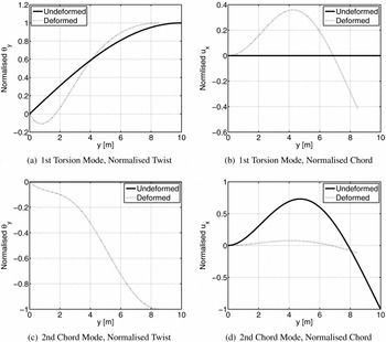
While for the flap- and chord-bending modes, the dimensionless-tip displacement appears to be the main driving parameter. For torsion, the same behaviour applies for aspect-ratio values between 12 and 20, as can be seen in Fig. 6(e). However, for higher values of aspect ratio, other factors gain relevance changing the trends of torsion frequency difference: first reducing the rate of frequency increase at lower vertical-tip displacements and then inverting the trend (AR = 24); finally, the frequency difference becomes monotonic decreasing with the vertical-tip displacement (AR = 28). Despite not being confirmed, this effect appears to be related to the coupling of the first torsion mode with the second chord mode as the wing undergoes larger deformations, phenomena observed when analysing the mode shape that corresponds to the first torsion mode at the non-linear aeroelastic equilibrium state (see the twist and chord degrees of freedom plotted in Fig. 7 for these two mode shapes).
First torsion and second chord-bending normalised modes shapes measured at the twist and chord degrees of freedom for the undeformed and deformed wing structures. This case corresponds to the AR = 28 wing for 10° of angle-of-attack.

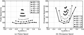
The flutter and divergence speeds variations with the dimensionless-tip displacement and wing aspect ratio are shown in Fig. 8. From Fig. 8(a), one can easily observe that the flutter speed decreases as the wing aspect ratio increases. However, the variation of the flutter speed with the tip displacement changes with the wing configuration because, for the wing with lower aspect ratio (AR = 12), the flutter speed decreases as the tip displacement increases, while for higher wing aspect ratios, the opposite behavior is observed.
Flutter and divergence speed variations with the dimensionless-tip displacement (Uz /(b/2)) and Aspect Ratio (AR).

In order to analyse more carefully the change of behaviour from the wing with an aspect ratio of 12 to the wing with an aspect-ratio of 16, a wing with an intermediate value of aspect ratio (AR = 14) was also analysed. From the extracted results, one can observe in Fig. 8(a) that the wing with an aspect ratio of 14 maintain the flutter speed nearly constant, i.e. independent of the tip displacement.
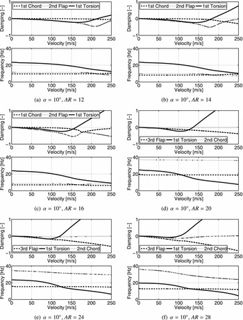
Different flutter mechanisms were noticed by decreasing the wing chord to increase the aspect ratio, as one can observe in the V-g (Velocity-Damping) and V-f (Velocity-Frequency) diagrams plotted in Fig. 9 for the 10° of angle-of-attack cases. First for lower aspect-ratio wing models (12, 14 and 16), the flutter phenomenon consists of a coupling between the first torsion mode with the second flap-bending mode, while for the higher aspect-ratio wing models (20, 24 and 28) the flutter process is comprised by the coupling of the first torsion mode with the third flap-bending mode. From these plots, there are several interesting effects that can be reported: (1) the first torsion mode is the critical flutter mode, and it becomes unstable at a lower airspeed as the wing aspect ratio increases; (2) for the lower aspect-ratio wings (12, 14 and 16), both the damping and frequency of the first chord-bending mode and second flap-bending mode cross after the flutter is predicted to occur; (3) note that for the high aspect-ratio models (24 and 28) and high angles of attack, the first torsion and second chord-bending modes start to have a similar behaviour in frequency, which was also observed in the mode shapes’ analysis at the aeroelastic equilibrium state.
V-g and V-f diagrams for 10° of angle-of-attack for the wings with aspect ratios of 12, 14, 16, 20, 24 and 28.

It is worth noting that the methodology employed here predicts the flutter speed at the aeroelastic static equilibrium position. Despite several load cases being applied to achieve different deformed states, the speed at which the flutter is predicted to occur is much higher than the one used to compute the aeroelastic equilibrium state. Therefore, in the future, further investigations are required to verify if this behaviour is maintained for even higher wing deformations. Nevertheless, it provides a faster solution than a more expensive time-domain method and accounts for more detail than simply computing the flutter speed at the wing undeformed state.
Regarding the divergence speed, one can notice from Fig. 8(b) that the divergence speed decreases as the wing aspect ratio increases, and increases as the tip displacement also increases. For the higher tip displacement, no divergence was found within the analysed range. It is observed as well that for all the analysed cases, the divergence speed is always above the flutter speed. The mode leading to divergence is the first flap bending.
7.0 CONCLUDING REMARKS
The current study presents aeroelastic design guidelines on the effects of high aspect ratio on the flutter response of wings. Linear and non-linear aeroelastic studies were conducted to analyse the effects of geometric non-linearities on high aspect-ratio wings. Significant differences between linear and nonlinear aeroelastic equilibrium solutions were found. These differences were observed to increase as the wing aspect ratio increases. However, the main cause of this behaviour is not the increase on wing aspect ratio per se, but rather the reduction on wing mass, torsional stiffness and bending stiffness, which weakened the wing, rendering it more flexible and prone to higher deformations. The increase in deformation makes the difference from linear to non-linear solutions in the deformed state more evident (mainly due to the variation on twist/incidence angle spanwise distribution), on the spanwise dimensionless lift distribution and on flutter speed. A nearly linear correlation of flutter speed difference between linear and non-linear results with vertical-tip displacement difference is observed.
From the aspect-ratio study, it was observed that by increasing the wing aspect ratio, the flutter and divergence speeds vary substantially and that the divergence speeds always remains above the flutter speed. The high deflections were observed to cause substantial changes in the flutter speed. The variation of the flap- and chord-bending modes natural frequencies were found to have the same behaviour for all the aspect-ratio wings if the same dimensionless-tip displacement is considered. Nevertheless no similar correlation was found for the torsional mode natural frequency for values of aspect ratio higher than 20, for which the first torsion and second chord-bending modes start to couple. Also from this study, the flutter mechanism was observed to change from a coupling between the first torsion mode with the second flap-bending mode (for the lower aspect-ratio wings, 12–16) to a coupling between the first torsion mode with the third flap-bending mode (for higher aspect-ratio wings, 20–28) as the wing aspect ratio increases. Therefore, although significant changes in flutter speed occur due to high wing deformations, it is not possible to conclude how those changes affect the safety margin for flight operation.
ACKNOWLEDGEMENTS
The presented work was carried out as part of the EU Seventh Framework Program Project NOVEMOR and the authors thank the European Commission for funding this research (Grant Agreement 285395). This work was also supported by FCT, through IDMEC, under LAETA, project UID/EMS/50022/2013. Furthermore, the NSERC Canada Research Chair and Discovery Research Grants are also acknowledged.