




No CrossRef data available.
Self-configuring components approach to product variant development
Published online by Cambridge University Press: 28 January 2005
Abstract
The use of modularity in the design of a new product or the adoption of a product platform, as the base to define new solutions within a product family, offers the company a chance to meet diverse customer needs at low cost because of economies of scale in all phases of the product's life cycle. At present, the concept of modularity in product design is becoming widely used in many industries such as automobiles and consumer electronics. However, if modularity and mass customization have attracted the interest of industries and researchers, the greatest efforts have been focused on the theoretical aspect whereas the related design support technologies have been only partially implemented. In this context, our intent is to develop highly reusable models, which are able to reconfigure themselves on the basis of new functional requirements. The proposed approach is based on the definition of what we call self-configuring components and multiple-level functions. To describe the approach, a practical example related to the design of modules for woodworking machines is reported.
Information
- Type
- Research Article
- Information
- Copyright
- © 2004 Cambridge University Press
1. INTRODUCTION
The market today forces companies to offer a large variety of products to their customers. Obviously, this proliferation of products may lead to the deterioration of production processes and higher costs (manufacturing, administrative, quality assurance, etc.; Lee & Billington, 1994). The goal of mass customization (Pine, 1992) is to adopt new product development methodologies to offer a large variety of products while maintaining low costs in production and in logistics. In most cases, the adoption of mass customization not only involves the design phase but it also has significant effects on many other parts of a company, such as business strategy, marketing, and manufacturing technologies, each of them having a diverse perspective on the same problem.
In this work we focus our research on the aspects related to product design. In the product design area, mass customization embraces many concepts: modularity, product architecture, product family, design for commonality, design for variety, and so forth (Otto & Wood, 2001). The majority of the literature describes theories and methods to support such concepts and highlights the benefits of their application, but in many cases the practical tools to support their implementation are neglected (Jiao et al., 2003). In this scenario, our aim is to study and develop suitable design technologies for small and medium enterprises (SMEs; Maupin & Stauffer, 2000).
A possible approach to mass customization is the development of a large variety of configurable product families. The design process of a configurable product takes place in two steps: the design for configuration and the configuration of the solution (Tiihonen et al., 1999).
The purpose of our work is to define a design system architecture to support the configuration of the solution phase. The proposed approach is based on the concept of self-configuring components (SCCs) and multiple-level functions (MLFs). By SCC we mean a structure with the capability of representing the different types of knowledge required to make the component able to fit different situations and provide the right configuration once the designer has defined the general requirements. Such structures are managed within an appropriate framework, which allows the structures to interact with each other, by means of exchanging required/provided MLFs to retrieve the information (at the right level of detail) required to behave correctly within the model. Simple components can then be used as constitutive parts for more complex modules, and they can be easily reused within new models because of their reconfiguration capabilities.
In this paper we define the structures able to represent SCCs and MLFs and we outline the framework architecture. To validate the approach, a real industrial case has been studied (components configuration for woodworking machines).
2. LITERATURE REVIEW
Configuration systems have been developed and applied in a number of domains, such as electronics, computer and telecommunications manufacturing sales, and chemical design, and in the construction of industrial plants. An overview on the different knowledge-based configuration approaches is given in Stumptner (1997). More recent researchers have approached the problem of configuration knowledge reuse and sharing by introducing the concept of the ontology of configuration (Soininen et al., 1998). Regarding the modular product development process, the methods presented in the literature are based on the concepts of product platform development or product families definition processes. Many researchers have focused their attention on product architecture and how it can be used to support customization. An interesting classification of modular product architectures (bus, slot, sectional) can be found in Ulrich and Eppinger (2000). The identification of a common architecture within the company product lines has been studied (Dahmus et al., 2000) to manage the product portfolio. Many researchers point out the advantages of designing products based on platforms and through the description of practical examples. The product platform definition and the application of reconfigurable products, product family configurations (Tichem et al., 1999), and the analysis of commonality to manage the product variety (Martin & Ishii, 1997; Kota & Sethuraman, 1998) are different aspects under investigation in the industrial and research world.
According to Simpson et al. (2001) a product platform can be defined as a set of parameters, features, and/or components that remain constant from product to product, within a given product family. Thus, it is a product representation from which product family members can be instanced. The applications of product platforms are described in several research papers. Two meaningful examples are in the product development for a family of hard disks (Siddique, 2001), in which the author focuses attention on the reduction of development time, and in the telecommunications subsystem design for a set of spacecraft (Gonzalez–Zugasti & Otto, 2000), in which it is shown how to establish an optimum degree of commonality. However, the study of the product platform has to be related to the product function definition phase. In fact, the product platform architecture can be represented as a set of functional modules that are collected to achieve a generic overall function. To satisfy the specific customer requirements (i.e., the specific overall function) it is necessary to construct an appropriate assembly of module instances. The generic correspondence between modules (physical components) and functions has been well established (Ulrich, 1995; Erixon et al., 1996; Pahl & Beitz, 1996). A basic problem is the definition of rules to map such physical elements with the functions represented in a complex functional structure. Stone et al. (1998), for example, develop three heuristics to identify possible modules. The idea has been extended to also include product family considerations (Stone et al., 2000). A further product family model based on a functional representation can be found in Jiao et al. (1998), who describe the product family as a combination of three views (functional, structural, and technical). An important functional classification that is a useful base to support the development of research in the product architecture definition and related design systems is reported in Hirtz et al. (2001).
However, in our opinion some issues still remain open. In particular, one issue regards the identification of efficient and coherent methodologies to integrate the nongeometric symbolic (and mainly explicit) information of such models, with the geometric numerical (mainly implicit) information required for the detailed description of the products' shape.
This integration is the essential premise to perform the analysis/synthesis cycle that is typical of the design process: functional and technological constraints are analyzed and then synthesized to identify a possible design solution, which involves the definition of preliminary shapes and dimensions. This geometrical information becomes part of the knowledge to be analyzed to perform the next synthesis step and to define a more detailed solution. This integration becomes very important during the configuration of a product variant, when the product model needs to be instantiated on the basis of configuration rules that have to reason on the knowledge related to the detailed definition of the product shape and dimensions.
In this last context, this paper provides an approach to allow the integration between configuration rules, functions, and shape representation. After establishing and determining the modularity of a specific production and a generic product platform, in terms of functional modules, the designer has to select the best module assemblies among many alternatives. The designer must configure every module instance while considering the impact that each single selection has on the final product in terms of costs, performance, assemblability, and so on. Such a task is generally intuitively performed on the basis of the expert's personal skill. If a correspondence between functions, modules, and basic geometric and nongeometric features can be formalized, the model of module instance could be accomplished in a very short time on the basis of configuration rules that are able to perform geometric and nongeometric queries on the model.
3. DESIGN PROCESS OF CONFIGURABLE PRODUCTS
A product can be defined configurable if, on the basis of the market requirements, it is possible to accomplish a rapid and low-cost design modification that fully satisfies the customer specifications. The design process of a configurable product takes place in two steps: the design for configuration and the configuration of the solution.
Design for configuration is the process that defines the product platform. During this phase, the designer establishes functional and technological properties as well as dimensioning and assembling the rules of the basic and optional components that can be combined to form the final product. To perform this task, the designer must identify the best compromise among a set of conflicting constraints, taking into account the existing relationships among materials, raw shapes, overall dimensions, strength conditions, manufacturing processes, and technological constraints of the product components. The knowledge acquired during this design phase (configuration model knowledge) specifies the set of possible configurations of the product.
It is important to note that the detail of the geometrical information required during this phase is quite limited: raw shapes, bounding boxes, axis locations, and so forth.
The configuration of the solution is the process that defines a specific member of the product family to meet the user's needs. During this phase, the domain expert must select the best solution among many options (sometimes 100s or 1000s), and he/she must immediately understand the impact that each single selection has on the final product in terms of costs, parts compatibility, functionality, performance, marketing constraints, and so forth. From a practical perspective, this last step should be handled with tools that simultaneously manage the design knowledge base (design rules, functional constraints, etc.) derived from the design for configuration process and the detailed geometrical model of the product. Work done in this field is described in the literature (Mandorli, Berti, & Germani, 2002; Martinez–Larrosa & Siddique, 2002). In the present work, we are interested in the variability within a product family (member configuration). It is known that the evolutionary design or variant design, when a modification of an existing product is required, is the most common design activity in a design department. The variant configuration can be achieved by deciding a combination of the different possibilities. Obviously, customer requirements could be satisfied by adopting several alternative solutions. The researchers' intent is to automate the configuration phase so that the designer can analyze the different possibilities in a short time (Germani et al., 2001).
From a technological point of view, the evolution trend of design support systems has moved from geometry-based systems [parametric/feature-based computer-aided design (CAD) systems] toward knowledge-based systems, with the aim of representing not only the product itself but also the design process of the product.
By using a parametric/feature-based CAD system, the designer interacts with the system to define the product shape in terms of basic entities (geometric features), which can be eventually associated with a functional or technological meaning. However, these systems, which can be used to produce a geometrically detailed design solution, made by 1000s of features (with related parameters), are not able to capture and store the complex reasoning that leads to the definition of that particular solution. (What is still missing is why the designer has used those features and parameters.) This lack of information makes it very difficult to reuse the model because it is not easy to understand which features and/or parameters should be modified to generate a new and stable model variant.
Conversely, knowledge-based systems attempt to capture design knowledge in an automated decision-making format. Traditional expert systems are based on inference rules and inference engines that, starting from an initial state, try to find a sequence of application rules that can lead to a valid final state (goal). These types of systems are driven by heuristic functions that are charged to evaluate if the system is converging step by step to the goal (Payne & McArthur, 1990). Because these systems do not have built-in geometric functionality to describe mechanical products, it is very difficult to define rules that are able to perform geometric reasoning.
Knowledge-based engineering systems (as defined in Sainter et al., 2000) are based on a generative approach (Mandorli, Rizzi, et al., 2002). The design process definition is called a product model, which is a tree structure made by attributed parts and subparts, that able to represent and store all the different types of information that define the decision process the designer follows during the design of the product. Part attributes can be generic values, expressions, if-then-else rules, and shape representations, because of the ability of the kernel to create and manipulate geometric data. The product model structure is traversed to apply relevant procedures and automatically generates a product design. When the design specifications change, thanks to the demand driven processing and dependency backtracking mechanisms, the system automatically updates the product model and generates new design versions by directly deriving all the outputs.
These kinds of systems are very effective in the generation phase. However, they are very limited in providing support during the definition of the tree model, which is the premise to use this technology. Moreover, if a valid variant has not been included in the tree structure, it will never be generated (Mandorli & Bordegoni, 2000).
To achieve an effective and rapid product variation in mass customization, it is fundamental to implement complex and efficient design tools that are able to define, represent, and coherently manage the geometric and nongeometric knowledge related to both the product and the product's design process.
Our approach to design a support system for product variant development is based on the concept of SCC exchanging MLFs.
The SCC concept is used to aggregate the knowledge required to configure the component itself. The product model is then made by a set of SCCs that use methods to exchange information by means of MLFs.
4. SCC APPROACH TO CONFIGURATION
The design phase of a new product needs to handle a lot of information, such as functions, design form features, geometrical shape, and assembly layout. Such complexity can be reasonably automatically managed only if the object architecture (we intend component or subassembly or assembly, on the basis of the product level analyzed) is known or if it is somehow interactively definable. This is possible within a modular product context, because modules have a predefined architecture related to the functional definition. Hence, we concentrate our efforts on the product variant determination process for a configurable product.
Up to now the method has been applied for the module configuration task. A two-step process has been considered: the module architecture instantiation and the detailed module/components configuration. The information defined during the first activity is used to automate the execution of the second phase, because of the use of SCCs and MLFs.
Initially, it is necessary to define the generic module architecture. Such a structure is the base to customize the specific module layout. The designer can use a simple geometrical representation (planes, axis, bounding boxes) to sketch the functional objects involved; such elements are interactively positioned in a 3-dimensional (3D) environment. References to provided or requested functions are encapsulated into the object definition as object attributes. The designer also decides a priority order among the components. This order is inherent to the design flow, and it tells the system from which component the configuration process starts.
Once the generic module architecture has been defined, the designer can set specific customer requirements and start the automatic configuration. As an example of a module variant, consider the possibility to add or delete components, decide meaningful model dimensions (e.g., layout constraints), or add or remove functions related to the specific case.
The automatic configuration process is able to move from the module architectural definition to its detailed description because of the knowledge encapsulated within the SCCs and the information exchanged among SCCs by means of the exchange of MLFs. The detailed description of the module comes from the detailed description of each module component. A detailed description of a component includes information about the shape, dimensions, and spatial location, as well as a set of attributes useful for the product development activities (cost estimation, definition of machining operations, execution of 2D drawings, optimization analysis, etc.).
Therefore, the type of knowledge to be encapsulated into the SCCs includes rules to select standard components from databases, geometric functions to generate the component shape and dimensions, and functional and technological knowledge. Functional and technological knowledge can be related to shape by using form features.
The SCC initial information comes from the module architecture previously instanced, which is functional information and layout information. To perform the component detailing, the SCC uses appropriated methods to look for required functions from others SCCs. By following this approach, the specific form features instances required for the detailed description of the component can be determined by the context, if it is already defined (when the component makes a query to other components of the module architecture it can also extract information on previously instanced features); or they can be interactively decided if they are related to interfaces with components at a low level in the module design priority order.
5. STRUCTURES TO SUPPORT THE SCC APPROACH
5.1. SCC knowledge representation
We now look at the SCC as a customer of input functionality and a supplier of output functionality (see Fig. 1).

A representation of the SCC concept.
The product model is then made by a set SCC, organized within a module architecture, that exchanges inputs and outputs. The more the design process advances and the more detailed the information becomes, the more the SCCs will produce detailed component configurations. Therefore, the model of the module will be more detailed.
A key point to define SCCs as a customer/supplier of functionality is the classification of functions. Hirtz et al. (2001) provide a well-structured functions taxonomy. We divide them into two main groups: internal functions and interface functions.
An internal function requires information located within the SCC component and does not exchange information with the context. An interface function connects two or more SCC components, and it implies a flow of information (signal, energy, and design information with different levels of abstraction) within the product model. The interface functions are defined to be represented as required/provided functions (e.g., import/export energy). If an SCC component requires a certain function X, then another component able to provide the function X should be present in the product model structure.
As an example, consider a shaft with two gears positioned at the two ends. The shaft receives torque and rotation from the driving gear, and it transports the energy to the driven gear. This exchange of energy can be represented within the shaft with a couple of interface functions (“receive energy” and “give energy”) and an internal function (“transport energy”). The gears components definition must respectively include an interface give energy (the driving gear) and an interface receive energy (the driven gear).
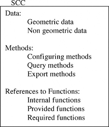
From the knowledge representation point of view, we define an SCC as a frame structure made by internal data, methods, and reference to functions. The internal data are the basic information that define the component. The set of methods defines the configuration engine. The reference to functions is used to drive the communications with the other SCCs that are part of the module architecture.
Internal data are stored as property name/property values couples (e.g., part_name = shaft). We distinguish between geometric and nongeometric types of values. Nongeometric types include the following:

Geometric types include the following:

The geometric values are managed through calls to a geometric kernel.
The methods are separated into three different types: configuring methods to perform the computation required to configure the component (including the computation of the shape type and dimensions), query methods to look to the other SCCs for the data required as input of the configuring methods (e.g., functional information and technological constraints), and export methods to export to the other SCCs the information about the component functionality (including information about shape, dimensions, and provided functions).
Configuring methods are used to manage internal functions. Query methods and export methods are used to respectively manage required and provided interface functions.
The SCC structure can be graphically represented, as shown in Figure 2. The knowledge encapsulated into the SCC data and methods is used to make the SCC evolve simultaneously with the configuration process, on the basis of the level of detail of the required and provided functions.

The SCC structure.
The next section describe the functions structure to which the SCC refers. Such a structure is defined to be able to represent the functions' multiple levels of abstraction.
5.2. Multiple level representation of functions
A key aspect of our approach is the possibility to perform the configuration at different levels of detail (see also Susca et al., 2002). The level of detail of the SCC configuration depends on the level of detail of the inputs retrieved by the query methods (i.e., if the configuration engine has enough information, it can produce more detailed configurations and it can provide more detailed outputs).
In the shaft example, the geometric information used to represent the shaft can be a simple line segment located in 3D space. It could become a cylinder when the information to perform the dimensioning is available. Finally, it may have a more detailed shape when form features are added to the cylinder to define the shaft interfaces to other components (e.g., key housing).
This concept is quite evident when we refer to the SCC geometric properties, but functions also have a similar need: in the shaft example, the receive energy function is an abstract concept. To be able to compute shape properties, the receive energy function needs to be mapped into a less abstract concept as “connect shaft and gear.” Therefore, functions should be represented with structures that are able to store functional information at different levels of detail/abstraction.
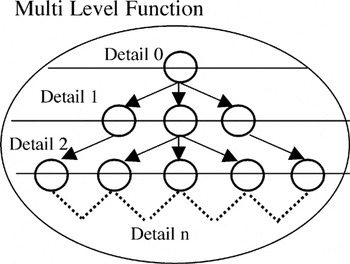
From the knowledge representation point of view, we define a multiple level function as a tree structure where each branch represents a different implementation of the root function, and the level of depth of the tree represents the level of detail of the function representation (see Fig. 3).

A representation of a multilevel function structure.
The nodes and leaves of the structure store the information required to define the function at a particular level of detail, including the geometrical information. The structure branches represent if-then-else rules that drive the context-dependent implementation of the function (referring to the shaft and gear example, the function “connect” can be a child node of the receive energy root function, and it may have the two child nodes “complete connection” and “partial connection”).
At the lowest functional level of detail, the function is related to the geometric information required to implement the function. This information is represented as traditional form features (holes, housing, etc.) and/or standard mechanical components (rolling bearings, pins, keys, screws, nuts, etc.). The form features and standard components description can be stored within appropriated databases linked to the function structures. Delving deeper into the shaft/gears example, when a function “guide rotation” is required from the shaft, and the dual function “support rotation” will be provided by another module component, such functions can be directly linked to a bearings database. When the shaft design information evolves (shaft speed, loads, etc.), it can be possible to automatically instance the required specific bearing.
5.3. Automatic configuration of SCCs
A module is defined by a set of SCCs instances related to each other by means of interface functions at the highest level of abstraction. The module architecture definition is performed in two steps: SCC instantiation and functions instantiation.
The user interactively performs the SCC instantiation by selecting the SCC from the SCC databases, setting the initial values of its data, and setting the reference to internal and interface functions.
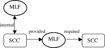
Once the SCCs have been instantiated, an automatic task is fired to instantiate the function structures. First, internal functions are instantiated: the SCC references to internal functions are identified, and relative functions structures are instantiated and placed into a relationship with the SCC (the appropriated configuring methods are set in the SCC). Second, the interface functions are instantiated: couples of SCCs, referring respectively to the requested/provided version of a function, are identified. Third, the function structure is instantiated and related to the couple of SCCs by setting the appropriated configuring as well as query and export methods. Both internal and interface functions are selected from the functions database. Figure 4 gives a graphical representation of the relationships among SCCs defined using MLFs.

A representation of relationships among SCCs.
The module structure can be formalized through a graph representation (Du et al., 2002), where nodes are SCCs and MLFs and oriented arcs are references to functions.
6. SYSTEM ARCHITECTURE TO SUPPORT SCCs
The framework to support the SCCs approach to product variant development should provide general functionality to initially set the module architecture, to relate SCCs by using reference and instances of MLFs, to manage the flow of information among SCCs and MLFs, which drives the configuration process, as well as functionality for the geometric representation of the SCCs shape. Moreover, the user should be able to extend the system by defining new SCCs and MLFs.
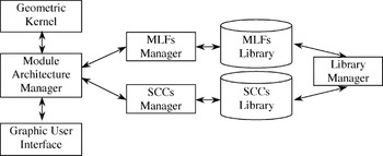
The proposed system architecture to implement the required functionalities is based on a set of software modules and libraries, organization as shown in Figure 5. The modules and the related features are now described.

The system architecture for module configuration.
6.1. Graphic user interface
This is dedicated to the user interaction. The user can take advantage of the functionalities provided by this software module to sketch the architecture of the configurable module by selecting SCCs from the SCCs library, set SCC initial data, add references to internal and interface functions, and set a priority order among SCCs.
6.2. SCCs manager
This manager provides functionality to manage the SCCs, including procedures to select and instantiate SCCs from the libraries and procedures to manage the SCC internal data and methods.
6.3. MLFs manager
It provides functionality to manage the MLFs, including procedures to select and instantiate MLFs from the libraries, and procedures to manage the level of detail to which the function is represented.
6.4. Module architecture manager
This is the core module of the system. It provides functionality to manage the module data structure made by SCCs that are related to each others by means of requested and supplied MLFs.
6.5. Library manager
This provides functionalities to manage the SCCs and MLFs repositories.
6.6. Geometric kernel
The geometric kernel is the geometric engine charged to the geometric computation of the SCC shape.
6.7. SCC library and MLF library
They are the repository for components and functions.
7. EXAMPLE OF USE OF SCCs
7.1. Context
To validate the proposed approach, the configuration process based on the use of SCCs and MLFs, as previously presented, was applied in a real test case. The prototype system was implemented by using currently available CAD technology that is open to customization by using software development kits.
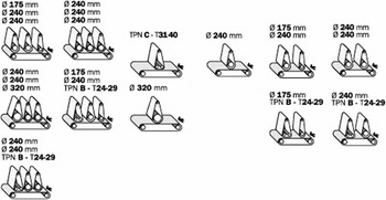
The project was carried out in collaboration with an Italian small industry that produces woodworking machines to sand wood panels. The different product lines were analyzed to identify a common product platform. The analysis was performed according to a method proposed by Stone et al. (1998). The most important functional module of the machine is made of one or more assembled sanding groups. A sanding group is made of a set of rollers and sanding bars that move sandpaper tapes. The pressure exerted on the panels allows the removal of the material. The machines are provided with a rubber slat conveyor to move the panels along the axis of the machine itself. The product variants are influenced by the wood panel size, the desired surface finishing, the wood typology, and finally, the shape of the panel (flat or shaped). Such parameters become constraints for the designers, and they are mapped into design variables as follows: number of rollers, diameter of rollers, slat conveyor width, tool typology, and roller pressure on the panels. Figure 6 shows different configurations of the sanding groups.

Different configurations of the sanding groups.
7.2. The sanding module configuration process
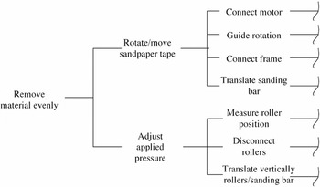
The overall function associated with a sanding group module is “evenly remove the material from the wood panel.” The module was analyzed to determine its functional structure. It is known that the module itself is a collection of submodules, which can or cannot be present according to the customer requirements (e.g., if a set of functions is required, the sanding bar is necessary). In Figure 7 we report a part of the complete functional structure of the sanding module, using the Functional Analysis System Technique (Otto & Wood, 2001) diagramming method. The material removal function (overall function of module) was decomposed in the subfunctions as described and structured in the diagram. Some functions can be omitted if the specific solution does not require them.

The functional structure of the sanding module (FAST representation).
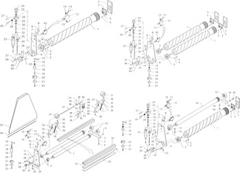
The module configuration is performed through the embodiment of these functions, customizing the design solution on the basis of customer requirements. This means assembling in an appropriate layout of manufactured/customized components and commercial/standards components. Figure 8 illustrates four different configurations of the module.

Examples of different sanding module configurations.
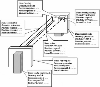
The components and submodules that are present in the generic module architecture are rollers, sanding bars, support plates, sandpaper tape, bearings housings, bearings, and vertical movement mechanisms. The module layout is represented in Figure 9. Rollers can be sketched as an axis; sanding bars, support plates, bearings housings, and movement mechanisms can be considered prismatic elements (bounding boxes are used). Finally, rolling bearings are standard components that can be sketched as lines.

The generic architecture of the sanding module.
When the module is defined for the first time, the designer selects the appropriated SCCs from the SCC database, sets their data, and defines references to the internal and interface functions through the selection from the MLF database. The designer also sets an order of design priority (i.e., in the studied module, rollers must be designed before the height control mechanism, support plates must be designed after such mechanisms, etc.). As an example, the SCC definition of the sanding roller includes the following information:

In this work we do not take into consideration the problem of module external interfaces (frame, motors, wood panel, etc.), because it would involve the configuration of the entire assembly. Hence, some interface functions do not have the corresponding dual function within the module itself because they are external interface functions; for example, within the roller definition the required function is receive energy (rotation and torque), but this function is provided by the electric motor that is outside the sanding module. As a consequence, the function tree could not be detailed to arrive at the form feature.
Note that only rollers, sanding bars, and support plates are manufactured components. The other objects are standard components, and they can be retrieved from databases.
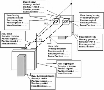
When a module variant is required, designers can load the generic structure and define the specific information to instance the module. Figure 10 shows the high-level representation for a two-roller solution (only some information is reported to simplify the figure interpretation). It is also possible to add meaningful dimensions in the sketch that are useful for the following detailing phase.

An instance of the module architecture for a two-roller solution.
To explain how the system can handle the evolution of the SCCs, we describe the configuration process of the support plate SCC.
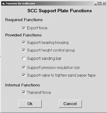
Support plates are referenced in Figure 8 with the number 6. The SCC definition of the support plate at the module architecture level includes data instantiation and references to internal and interface (required/provided) MLF functions. At this stage, geometric data to define the plate are limited to a bounding box; the position of the principal plane is determined through the instanced module architecture (the CAD model can be obtained as a protrusion). Concerning references to MLF functions, the referenced internal function is “transmit force.” The MLF structure for this function maps the configuration task to the selection and dimensioning of the profile shape. The profile is selected on the basis of geometric constraints and technological rules (i.e., the designer can use plates with rectangular or round shapes). The dimensioning procedure uses SCC internal data as parameters to compute the plate thickness. The unique referenced required function is “export force.” The referenced provided functions are “support bearings housing,” “support height control group,” “support sanding bar,” “support pressure regulation valve,” and “support of valves to tighten sandpaper tape.” These references to functions can or cannot be active on the basis of the configuration instance (e.g., if only the roller is present in the module architecture, the functions required by the sanding bar are deactivated).
The order of design priority is set as follows: rollers, sanding bars, height regulation and control mechanism, bearings, support plates, and housing bearings. The configuration process starts when the design parameters (wood panel typology, thickness, surface finishing, etc.) are set. The values of these parameters allow the instantiation of rollers or sanding bars (type, shape, dimensions, material, etc.). The height regulation and control mechanism is a standard submodule, which depends on the rollers' characteristics (or sanding bar's characteristics). The choice of bearings is made by using standard rules. When the process comes to this point, the support plates need to be instanced. By looking at the structure of the referenced MLF functions, the system decomposes support bearings housing into “position bearings housing” and “secure/constraint bearings housing.” The system then looks for dual functions of the decomposed function within the other SCCs that are part of the module. When an SCC referring to a dual function is identified, geometric information is collected and used to configure the plate SCC. The level of detail of such information depends on the level of configuration the dual SCC has reached (i.e., if within the height control mechanism the function requiring the positioning is embodied with two screws, the plate must provide two threaded holes in the same position). By repeating this process for all the provided and requested functions, a set of form features for the support plates is instanced and positioned in the bounding box representing the plate. A preliminary geometrical instance can be obtained.
For the bearings housing, which follows the support plate in the design order, the interface function is not yet solved. It depends on the support plate thickness, and such a parameter is identified by transforming the internal function “transmit force” in a form feature. In fact, such a function requires design parameters (loads, a preliminary plate geometry, constraints, material) to determine the thickness value. When the information is known, the housing can be instanced and the interface functions can be embodied. When all the functions are embodied, the configuration process is complete.
7.3. Prototype system implementation
At present, only a prototype version of the software tool has been implemented to test the proposed ideas. The objective was the simulation of the configuration process based on the SCC and MLF concepts. From the practical point of view, the implemented solution integrates a parametric feature-based CAD system, a user interface, and a database to manage the design information. To respect the constraint of applicability within an SME industry, inexpensive, easy to handle, commercially available software (Solid Edge by Unigraphics; Visual Basic, Excel and Access by Microsoft) was chosen. The core of the configuration system was implemented using Visual Basic Language.
The system communicates with the geometric engine through the Application Protocol Interface provided by the CAD software development kit. Communication with the geometric model is bidirectional: one way to make queries to get implicit geometric and topological information from the model, and the other way to generate shapes in terms of form features related to functions.
The SCCs are defined as structures that are able to store functional and topological attributes, as well as procedures to query the linked geometric model. The MLF structures include procedures to generate geometry by using functional and technological attributes as parameters. The multiple level representation of functions is implemented through different procedures that are able to generate shapes with different levels of detail.
In the present implementation, when an SCC is selected, an interface is presented to the user where he/she can activate or deactivate functions. An example related to the support plate definition is shown in Figure 11.

The user interface to define the module context.
The related form features are determined by looking into the MLF structures. When an MLF has alternative design solutions (i.e., different possible features can be used to provide the function), the system asks the user to interactively select the desired option.
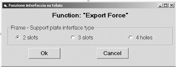
For example, the export force function of the plate component can be provided in different ways, corresponding to the different form features: two slots, three slots, or four holes. Figure 12 shows the interface used to interact with the user.

The input window for the export force function.
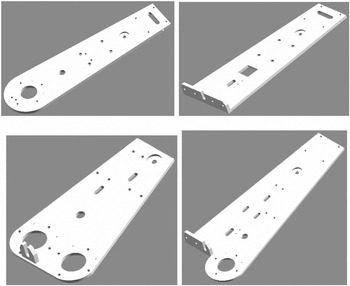
Once the internal and interface functions of the SCC structure have been mapped into form features, the system automatically generates the 3D model of the component, taking advantage of the geometric kernel of the integrated CAD system. Figure 13 shows different configurations of the support plate SCC, which were obtained by changing some of the provided and requested functions.

Four self-configured models of the support plates.
8. CONCLUSIONS AND FUTURE WORK
The advantages of modularity and product platform adoption for a rapid configuration of a new product variant are well known. New theories and methodologies will continue to be at the core of many research efforts. In this context, the task to completely automate the procedure for product configuring is enormous and very stimulating. However, with the development of improved design technologies that can automatically manage the design information at different levels of detail, meaningful progress can be made.
The framework presented in this work is a move toward the realization of such a goal. The framework is based on a multilevel structure of functions that are able to handle multiple views of a product and on objects encapsulating different product knowledge typologies. These objects are SCCs. They make reference to functional information, which is then mapped into features; and they encapsulate information about design rules and manufacturing rules. They support the design process by providing the information with an appropriate degree of abstraction and detail on the basis of the specific design phase. Current design technologies were used to develop a prototype configuration system based on SCC and MLF concepts. An example was presented in to illustrate how the system could be used in practice.
This study allowed the determination of advantages and limitations. First, the system cna support the configuration of a product variant in a very short time, generating a 3D CAD model usable for optimization, cost estimation, and definition of manufacturing processes. Second, it is conceived to represent the designer's way of thinking because it manages a high-level module architecture and a module functional structure. Hence, the designer does not need to know about geometric and topological entities handled by the system. In contrast, much research and development work still remains to improve the system. Two main objectives can be highlighted: a better, and complete, knowledge formalization among functions and form features, which involves the use of semantic features.
References
REFERENCES
Dahmus, J.,
Gonzalez–Zugasti, J., &
Otto, K.
(2000).
Modular product architecture.
Proc. ASME 2000 Design Engineering Technology Conf.
DETC'00, Baltimore, MD, September 10–13.
Du, X.,
Jiao, J., &
Tseng, M.
(2002).
Graph grammar based product family modelling.
Concurrent Engineering: Research and Application
10(2),
113–128.Google Scholar
Erixon, G.,
Von Yxkull, A., &
Arnstroem, A.
(1996).
Modularity—The basis for product and factory reengineering.
Annals of the CIRP
45(1),
1–6.Google Scholar
Germani, M.,
Berti, S.,
Mandorli, F., &
Otto, H.
(2001).
Design of product families: an example within a small and medium
sized enterprise.
Proc. 13th Int. Conf. Engineering Design ICED'01, Design
Methods for Performance and Sustainability, pp.
507–514,
Glasgow, August 21–23.
Gonzalez–Zugasti, J. &
Otto, K.
(2000).
Modular platform-based product family design.
Proc. ASME 2000 Design Engineering Technology Conf.
DETC'00, Baltimore, MD, September 10–13.
Hirtz, J.,
Stone, R.,
McAdams, D.,
Szykman, S., &
Wood, K.
(2001).
Evolving a functional basis for engineering design.
Proc. ASME 2001 Design Engineering Technology Conf.
DETC/DTM'01, Pittsburgh, PA, September 9–12.
Jiao, J.,
Ma, Q., &
Tseng, M.
(2003).
Towards high value-added products and services: Mass customisation
and beyond.
Technovation
23(10),
809–821.Google Scholar
Jiao, J.,
Tseng, M.,
Duffy, V., &
Lin, F.
(1998).
Product family modeling for mass customisation.
Computers and Industrial Engineering
35(3–4),
495–498.Google Scholar
Kota, S. &
Sethuraman, K.
(1998).
Managing variety in product families though design for commonality.
Proc. ASME 1998 Design Engineering Technology Conf.
DETC'98, Atlanta, GA, September 13–16.
Lee, L. &
Billington, C.
(1994).
Designing products and processes for postponement. In
Management of Design
(Dasu, S. &
Eastman, C., Eds.), pp.
105–122.
Boston:
Kluwer Academic.
Mandorli, F. &
Bordegoni, M.
(2000).
Product model definition support for knowledge aided engineering
application development.
Proc. CD-ROM of DETC'00, ASME 2000 Design Engineering
Technical Conf. and Computers and Information in Engineering
Conf., Baltimore, MD.
Mandorli, F.,
Berti, S., &
Germani, M.
(2002).
A KBE system to manage the module configuration using the corporate
knowledge.
Proc. 7th Int. Design Conf. Design 2002,
Vol. 1, pp.
385–390,
Dubrovnik, May 14–17.
Mandorli, F.,
Rizzi, C.,
Susca, L., &
Cugini, U.
(2002).
An Approach to implement feature-based applications using
knowledge aided engineering technology. In
Feature Based Life-Cycle Modeling
(Soenen, R. &
Olling, G.J., Eds.), pp.
41–55.
Boston:
Kluwer Academic.
Martin, M. &
Ishii, K.
(1997).
Design for variety: development of complexity indices and design
charts.
Proc. ASME 1997 Design Engineering Technology Conf.
DECT'97.
Martinez–Larrosa, J.A. &
Siddique, Z.
(2002).
CAD Support for product family design using parametrics, mating
relationships, and modularity. In
Advances in Concurrent Engineering
(Jardim–Goncalves, R. &
Steiger–Garcao, A., Eds.), pp.
434–543.
Cranfield, MA:
Balkema.
Maupin, A. &
Stauffer, L.
(2000).
A design tool to help small manufacturers reengineer a product
family.
Proc. ASME 2000 Design Engineering Technology Conf.
(DECT/DTM'00), Baltimore, MD, September 10–13.
Otto, K. &
Wood, K.
(2001).
Product Design: Techniques in Reverse Engineering and New Product
Development.
Englewood Cliffs, NJ:
Prentice–Hall.
Pahl, G. &
Beitz, W.
(1996).
Engineering Design.
Berlin:
Springer–Verlag.
Payne, E.C. &
McArthur, R.C.
(1990).
Developing Expert Systems: A Knowledge Engineer's Handbook for
Rules and Objects.
New York:
Wiley.
Pine, J.
(1992).
Mass Customisation: The New Frontier in Business Competition.
Boston:
Harvard Business School Press.
Sainter, P.,
Oldham, K.,
Larkin, A.,
Murton, A., &
Brimble, R.
(2000).
Product knowledge management within knowledge-based engineering
systems.
Proc. CD-ROM of DETC'00, ASME 2000 Design Engineering
Technical Conf. and Computers and Information in Engineering
Conf., Baltimore, MD.
Siddique, Z.
(2001).
Estimating reduction in development time for implementing a product
platform approach.
Proc. ASME 2001 Design Engineering Technology Conf.
DETC'01, pp.
123–131,
Pittsburgh, PA, September 9–12.
Simpson, T.,
Maier, J., &
Mistree, F.
(2001).
Product platform design: Method and application.
Research in Engineering Design
13,
2–22.Google Scholar
Soininen, T.,
Tiihonen, J.,
Mannisto, T., &
Sulonen, R.
(1998).
Towards a general ontology of configuration.
Artificial Intelligence for Engineering Design, Analysis and
Manufacturing
12(4),
357–372.Google Scholar
Stone, R.,
Wood, K., &
Crawford, R.
(1998).
A heuristic method to identify modules from a functional
description of a product.
Proc. ASME 1998 Design Engineering Technology Conf.
DETC'98, Atlanta, GA, September 13–16.
Stone, R.,
Wood, K., &
Crawford, R.
(2000).
Using quantitative functional models to develop product
architectures.
Design Studies
21,
5–31.Google Scholar
Stumptner, M.
(1997).
An overview of knowledge-based configuration.
AI Communications
10(2),
111–126.Google Scholar
Susca, L.,
Mandorli, F., &
Rizzi, C.
(2002).
How to represent intelligent components in a product model. In
From Knowledge Intensive CAD to Knowledge Intensive Engineering
(Cugini, U. &
Wozny, M., Eds.), pp.
159–172.
Boston:
Kluwer Academic.
Tichem, M.,
Andreasen, M., &
Riitahuhta, A.
(1999).
Design of product families.
Proc. 12th Int. Conf. Engineering Design ICED'99,
Vol. 2, pp.
1039–1042,
Munich, August 24–26.
Tiihonen, J.,
Lehtonen, T.,
Soininen, T.,
Pulkkinen, A.,
Sulonen, R., &
Riitahuhta, A.
(1999).
Modeling configurable product families.
Proc. 12th Int. Conf. Engineering Design ICED'99,
Vol. 2, pp.
1139–1142,
Munich, August 24–26.
Ulrich, K.
(1995).
The role of product architecture in the manufacturing firm.
Research Policy
24,
419–440.Google Scholar
Ulrich, K. &
Eppinger, S.
(2000).
Product Design and Development
(Pahl, G., Ed.).
New York:
McGraw–Hill.

A representation of the SCC concept.
The SCC structure.
A representation of a multilevel function structure.
A representation of relationships among SCCs.
The system architecture for module configuration.
Different configurations of the sanding groups.
The functional structure of the sanding module (FAST representation).
Examples of different sanding module configurations.
The generic architecture of the sanding module.
An instance of the module architecture for a two-roller solution.
The user interface to define the module context.
The input window for the export force function.
Four self-configured models of the support plates.
 You have
Access
- 10
- Cited by