

1 Introduction
Research on mobile robots is one of the most popular topics in robotics and intelligent systems. No matter whether the robot is wheeled or a humanoid, it can autonomously navigate in an environment depending on algorithms for object detection and avoidance. Primarily, the movement of the humanoid robot is affected by obstacles that could make it fall and lose its balance. Obstacle avoidance is an important research topic in robotics, but designing an algorithm to let a robot to navigate autonomously in an environment and avoid obstacles is a complicated problem. Many researchers use infrared sensors (Benet et al., Reference Benet, Blanes, Simó and Pérez2002; Li et al., Reference Li, Chang and Tong2004), ultrasonic sensors (Li & Yang, Reference Li and Yang2002), or lasers (Hancock et al., Reference Hancock, Hebert and Thorpe1998; Soumare et al., Reference Soumare, Ohya and Yuta2002) to detect barriers. However, these methods have some defects: the search angle and search distance are limited. Moreover, if only a vision sensor is allowed, it is not easy for a robot to avoid obstacles and navigate in an unknown environment due to the planar image.
Some studies (Chao et al., Reference Chao, Hsueh, Hsiao, Tsai and Li2009; Chen et al., Reference Chen, Chiang and Wu2014) have used wheeled mobile robots with a vision system to navigate an environment without colliding with obstacles. They use either stereo vision (Chao et al., Reference Chao, Hsueh, Hsiao, Tsai and Li2009) or a Kinect sensor (Chen et al., Reference Chen, Chiang and Wu2014) to obtain the distance from the obstacle to the robot to perform the obstacle avoidance task. As the stability of moving wheeled mobile robots is higher than that of humanoid robots, the methods for wheeled mobile robots may not be applicable. Wong et al. (Reference Wong, Hwang, Huang, Hu and Cheng2011) proposed an algorithm for a humanoid robot turning left or right to avoid obstacles, but it seems too complicated for simple humanoid robots to record how many times they have changed directions and turn back to original direction to keep walking toward the destination. In addition, the algorithms (Wong et al., Reference Wong, Hwang, Huang, Hu and Cheng2011) calculating the angles of the obstacle from the robot may not be precise because the vision system is easily affected by the environment. For example, when the robot is walking and its visual angle may vary by head tilt and head moving. Even 5–10° difference obtained in the algorithm may cause errors ranging from 30 to 50 cm.
Computer vision is one of the ways of perceiving the environment, but webcam can only provide a planar image instead of a three-dimensional image with range distances. To obtain the depth of the obstacle, Budiharto et al. (Reference Budiharto, Moniaga, Aulia and Aulia2013) used stereo vision in a humanoid robot to avoid multiple moving obstacles. However, for humanoid robot competitions such as the FIRA HuroCup competition, obstacle avoidance is one of the events, called the obstacle run in the contest. In this competition, humanoid robots that can walk through an environment with many color obstacles such as file holders, paper board, and boundary lines need a real-time obstacle avoidance scheme to perform the task only depending on a vision system. Tradition methods for obstacle avoidance such as ultrasonic sensors and lasers cannot detect the color obstacle mentioned right above. However, in the current robotics market, a commercially manufactured humanoid robot cannot obtain stereo vision or depth information of an obstacle.
Therefore, an algorithm simply based on a planar vision system is proposed to accomplish the obstacle avoidance task and navigate through the environment autonomously. The rest of the paper is structured as follows. Section 2 describes the problem of obstacles and introduces the humanoid robot implemented in this study. An algorithm with fuzzy logic is proposed in Section 3. The experimental results are presented in Section 4 and the paper is concluded in Section 5.
2 Humanoid robot and the problem description
2.1 Humanoid robot
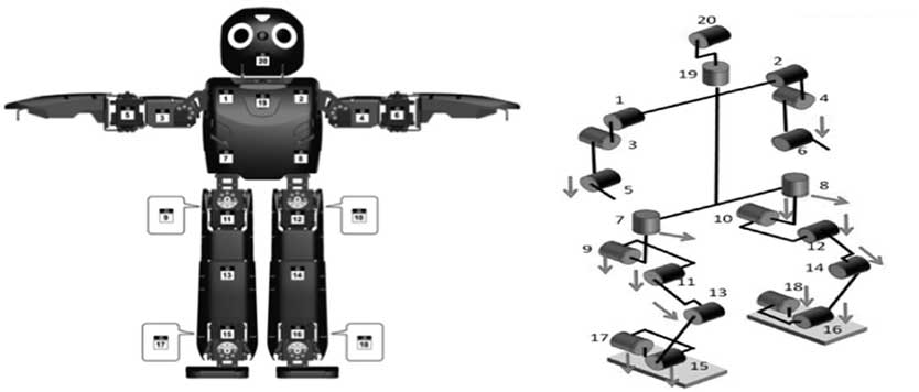
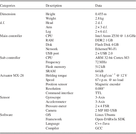
Figure 1 shows the humanoid robot DARwIn-OP, which is an abbreviation for Dynamic Anthropomorphic Robot with Intelligence–Open Platform, and its overall specifications are listed in Table 1. DARwIn-OP was developed by ROBOTIS and comprises 20 Dynamixel MX-28 actuators (Robotis, Korea). The actuators offer 6 d.f. for the legs as well as dual 3 d.f. arm movement and dual 2 d.f. neck movement. The robot is equipped with a USB 2.0 HD Logitech C905 camera (Logitech, Swiss). The camera is the only sensor equipped in the humanoid robot to avoid obstacles in the environment.
DARwIn-OP (Dynamic Anthropomorphic Robot with Intelligence–Open Platform) servo motor numbering and positions

Specification of DARwIn-Op (Dynamic Anthropomorphic Robot with Intelligence–Open Platform)

2.2 Problem description
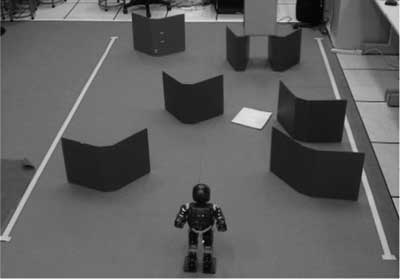
In this study, the robot moves from one end of the playing field to the other as quickly as possible following the rules of FIRA’s obstacle-run event in the HuroCup. The dimensions of the playing field are at least 300×400 cm. The challenge of the event is that wall obstacles in blue and ground obstacle in yellow cannot be overcome, as shown in Figure 2. Meanwhile, two boundary lines marked in yellow are also avoided by the robot.
Obstacles and robot

3 The proposed algorithm
3.1 Image processing
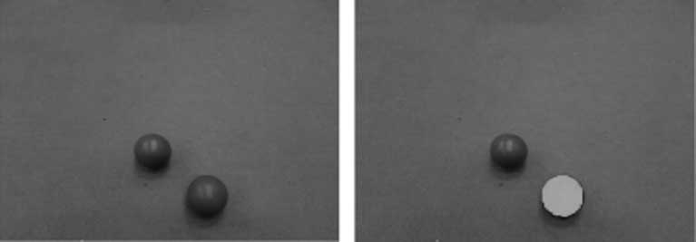
The camera is the only sensor for the robot and, according to the rules of the obstacle-run event, the color of the obstacles is blue. Hence, the image size of the environment is captured at 320 pixels wide and 240 pixels high (320 columns×240 rows). The image is transformed into a binary image. Then, the connected components labeling operation (He et al., Reference He, Chao, Suzuki and Wu2009) is used to distinguish the obstacles by assigning a unique label to each maximal connected region of foreground pixels. We use 8-connect components labeling so that a pixel has eight neighbors around it to mark the label. For example, two blue balls are shown in Figure 3. Although they have the same color, the connected components labeling operation marks the closer one in orange. Therefore, the connected components labeling process can be used to distinguish the obstacles of the blue walls.
Connected components labeling operation

3.2 Decision making for moving direction
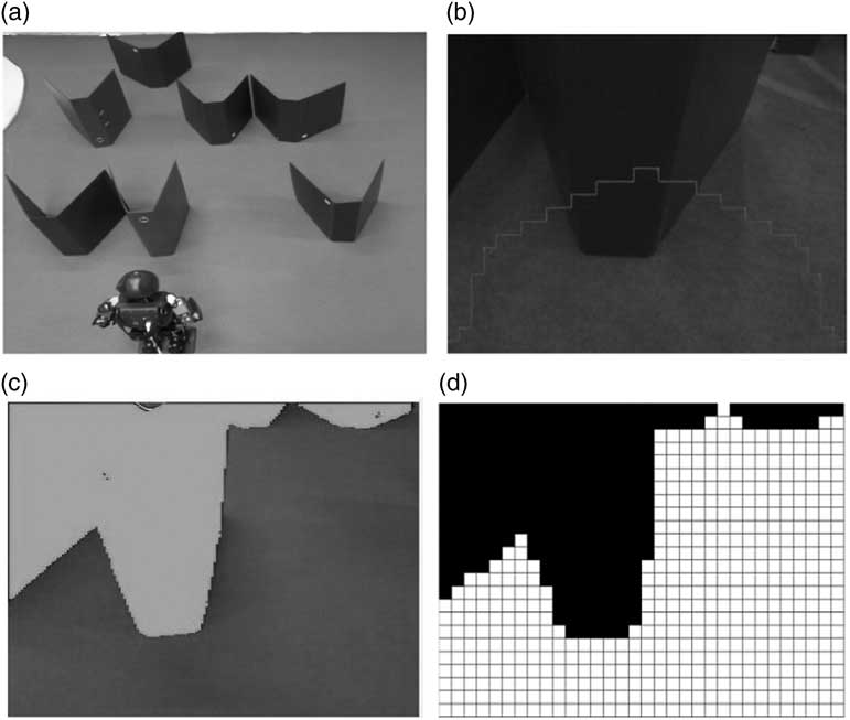
The color-coded model is first built to discover the obstacles. The image employs the connected components labeling method to remove the noise from the image, as shown in Figure 4. Next, the image is transformed into a binary image and image preprocessing techniques such as dilation and elution are used, and the image is reduced into a 32×24 grid (Hsia et al., Reference Hsia, Chang and Chiang2012), each grid being a 10×10 pixel square. To reduce the noise effect, the grid is marked in black if the pixels of the obstacle are >20 pixels in 10×10 (100) pixels. Figure 4 shows the obstacles and robot from top view, obstacles from robot’s view, color-coded obstacle from the robot’s view, and navigation grids in Figures 4(a)–4(d), respectively.
(a) Obstacles and robot from top view. (b) Obstacles from robot’s view. (c) Color-coded obstacle from the robot’s view. (d) Navigation grid

According to the navigation grid, the depth vector D is a 1×32 dimension vector and is obtained from the first obstacle’s location from the bottom row location for each column. Therefore, we have
 $$D\,{\equals}\,\left[ {d_{1} ,d_{2} , \cdots ,d_{{32}} } \right]$$
where d i is the distance of the first black grid location for the ith column.
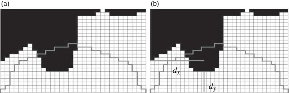
To prevent the robot from hitting the obstacle, the focus area that is in front of the robot is defined as shown in Figure 5:
 $$F\,{\equals}\,\left[ {f_{1} ,f_{2} , \cdots ,f_{{32}} } \right]$$
where
 $$f_{i} \,{\equals}\,\left\{ \matrix{ i,\quad \quad \quad 1 \, \les \,i \,\les 16 \hfill \cr 33{\minus}i,\quad 16\,\lt\,i\,\les 32 \hfill \cr} \right.$$
Focus area (a) and the distances (b) of the obstacle d y and d x

To check whether the obstacles are inside the focus area, define vector V in (4). If V is not equal to 0, then the robot needs to move because it indicates that the obstacle is inside the focus area:
 $$V\,{\equals}\,\left[ {v_{1} ,v_{2} , \cdots ,v_{{32}} } \right]$$
 $$v_{i} \,{\equals}\,\left\{ \matrix{ f_{i} {\minus}d_{i} ,\quad f_{i} \,\ges\, d_{i} \hfill \cr 0,\quad \quad \ f_{i} \,\lt\,d_{i} \hfill \cr} \right.,\,i\,{\equals}\,1,\,\ldots\,,32$$
Define the weighting factor in (6) and (7) to decide the direction in which the robot needs to move. If W L is greater than W R , the robot will move left and set the boundary point x b to be the furthest right point, 319. Otherwise, if W R is not greater than W L , the robot will move right and set the boundary point x b to be the furthest left point, 0. The boundary point x b is defined in (8):
 $$W_{R} \,{\equals}\,\mathop{\sum}\limits_{i\,{\equals}\,1}^{32} {(33{\minus}i)} {\times}v_{i} $$
 $$W_{L} \,{\equals}\,\mathop{\sum}\limits_{i\,{\equals}\,1}^{32} i {\times}v_{i} $$
 $$x_{b} \,{\equals}\,\left\{ \matrix{ 0,\quad \quad W_{L} \,\les\, W_{R} \hfill \cr 319,\quad W_{L} \,\gt\,W_{R} \hfill \cr} \right.$$
3.3 Obstacle avoidance by fuzzy logic control
To obtain the minimal distance from robot to obstacle, we have the boundary distance from the y direction d y , defined in (9) as the shortest distance from the depth vector D. The distance from the center point of x c defined in (10) to the boundary point x b from the x direction d x , shown in (11). The d y and d x shown in Figure 5 are the shortest distance of obstacles in a vertical direction and the distance from the center of the obstacle to the boundary, respectively. These two parameters are used in the fuzzy logic control system to decide the movement of the robot to avoid the obstacles:
 $$d_{y} \,{\equals}\,{\rm min}\{ d_{i} \} $$
 $$x_{c} \,{\equals}\,\left( {\mathop{\sum}\limits_{i\,{\equals}\,1}^n {x_{i} } } \right)\,/\,n,\quad (x_{i} ,y_{i} ) \in A$$
where A is a region with obstacles inside the focus area, and n grids are assumed in the focus area.
 $$d_{x} \,{\equals}\,x_{c} \,{\minus}\,x_{b} $$
The proposed scheme involves a fuzzy system that approximates any nonlinear function to arbitrary accuracy with only a small number of fuzzy rules (Mendel, Reference Mendel1995). According to the fuzzy system, it has three steps: fuzzification, fuzzy rule, and defuzzification. The fuzzy system diagram is illustrated in Figure 6.
Fuzzy system block diagram

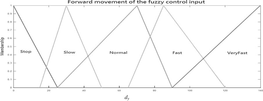
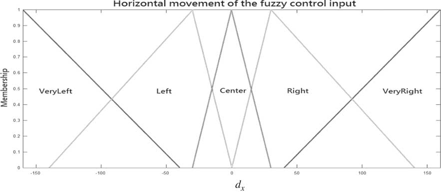
Fuzzification. The first step in fuzzification is to determine inputs and outputs, and choose an appropriate membership function for input and output that, for simplicity in implementation, selects a triangular membership function in this study. First, let us define the membership function for the inputs d y and d x , as shown in Figures 7 and 8, respectively. Here, d y is the forward movement and d x the horizontal movement of the fuzzy control input.
Membership functions for input d y

Membership functions for input d x

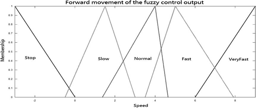
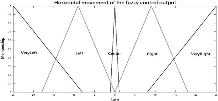
Then, we define the membership function for the output speed and turn, as shown in Figures 9 and 10, respectively. Here, speed is the forward movement speed and turn the horizontal movement of the fuzzy control output.
Membership functions for output speed

Membership functions for output turn

Fuzzy rule. If… then… is used to implement the fuzzy system. The rules are as follows:

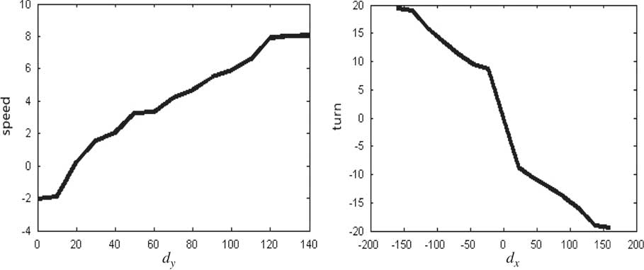
Defuzzification. This is used to transform a fuzzy set to a crisp set. Therefore, the input for defuzzification is the aggregate output, and the output of it is a crisp number. Based on fuzzy methodology, the center of gravity method is used in this study. Then, we have the nonlinear relationship between input and output for both pairs of (d y , speed) and (d x , turn), as shown in Figure 11.
Defuzzification of the output speed and turn

4 Performance analysis
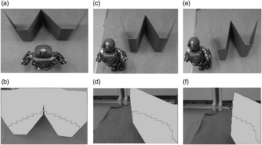
To illustrate the performance of the proposed algorithm, the experimental environment is established, as shown in Figure 12. First, we evaluate the situation where an obstacle is in front of the robot, as shown in Figure 12(a), and the robot’s corresponding vision is presented in Figure 12(b). Then, the robot moves left as per the proposed algorithm, as shown in Figure 12(c), and its vision is shown in Figure 12(d). The robot finds that the obstacle is still in the focus area; therefore, it follows the proposed scheme to move left more, as shown in Figure 12(e), and the vision for the robot is shown in Figure 12(f).
Experiment for testing the proposed scheme to avoid obstacles. The robot moves from (a), (c) to (e) and the corresponding vision is (b), (d) and (f), respectively

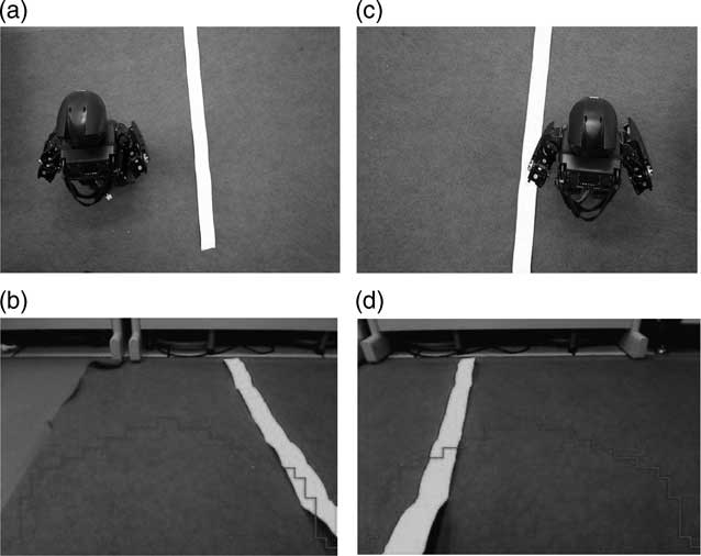
Next, we test the boundary lines to check whether the robot will avoid hitting the boundary lines. The experiment is illustrated in Figures 13(a)–13(d). The robot follows the algorithm to find both sides of the boundary lines and moves left or right to avoid stepping on the boundary lines in the event.
Experiment for testing the proposed scheme for boundary lines. The robot avoid both boundary line in (a) and (c) and the corresponding vision is (b) and (d)

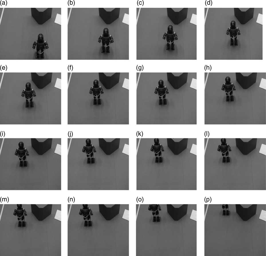
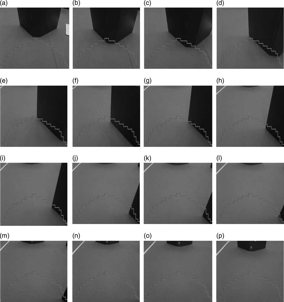
Finally, the continuous movement of the robot is evaluated in the experiment. According to the proposed algorithm, the robot obtains d x and d y from (1) to (11). Then, the fuzzy logic system for robot movement is established to get turn and speed. From Figure 14, we have the robot adjusting its steps to avoid the obstacles in Figures 14(a)–14(p). The corresponding visions obtained from the robot are shown in Figures 15(a)–15(p).We find that when the obstacle is in the focus area, the robot avoids it using the proposed algorithm until there is no obstacle in the focus area.
Continuous movement for the proposed scheme to avoid the obstacle. The robot moves from (a) to (p) in alphabetical order to avoid the obstacle

Corresponding vision from (a) to (p) in alphabetical order from the robot for the experiment in Figure 14 (a) to (p), respectively

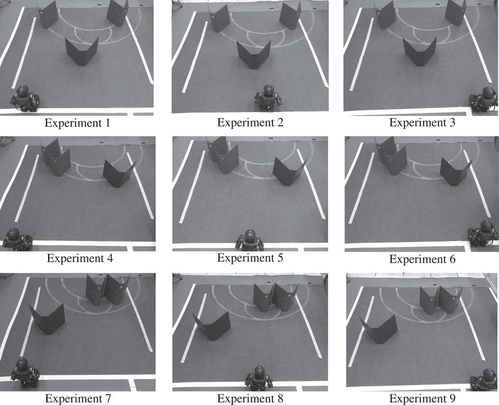
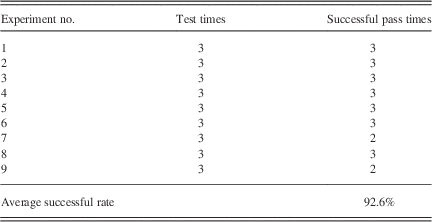
To show the performance of the algorithm, the repeatability test is carried out. The test experiments are shown in Figure 16. In Figure 16, the obstacles are located in the left, center, and right with equal and non-equal distribution and the robot stands on three different positions: left, center, and right. Each experiment is tested for three times and the result is summarized in Table 2 and it shows that about 92.6% of test experiments can pass the obstacles by the proposed algorithm.
Nine test experiments for the robot

Results of test experiments

5 Conclusions
This study describes an obstacle avoidance system for a humanoid robot employing just a webcam as its vision system. The proposed algorithm uses the image obtained from the robot to calculate navigation grids. We define a focus area that is the obstacle region that the robot needs to avoid. Therefore, the distances from y and x directions are calculated by the filter processes. Then, a fuzzy logic system is used to decide the speed and turn parameters for the robot. The experiment results show that the humanoid robot can avoid the obstacles and the boundary lines in an experiment and that it can access any route with its obstacle avoidance ability to implement the task of the obstacle-run event.
Acknowledgment
This work is supported by Ministry of Science and Technology of Taiwan under Grants: MOST 104-2221-E-130-012.