


1. Introduction
Structural geologists have long documented folds, refolded folds and sheath folds in ductile shear zones (Carreras, Estrada & White, Reference Carreras, Estrada and White1977; Rhodes & Gayer, Reference Rhodes and Gayer1977; Minnigh, Reference Minnigh1979; Henderson, Reference Henderson1981; Lacassin & Mattauer, Reference Lacassin and Mattauer1985; Faure, Reference Faure1985; Ghosh & Sengupta, Reference Ghosh and Sengupta1987; Holdsworth, Reference Holdsworth1990; Goscombe, Reference Goscombe1991; Mukhopadhayay et al. Reference Mukhopadhyay, Bhadra, Ghosh, Srivastava and Sengupta1997; Searle & Alsop, Reference Searle and Alsop2007; Alsop & Carreras, Reference Alsop and Carreras2007; Alsop, Holdsworth & McCaffrey, Reference Alsop, Holdsworth and McCaffrey2007). These studies have been complemented by several experimental and numerical simulations that provide an insight into the mechanism of refolding and sheath folding in shear zones (Quinquis et al. Reference Quinquis, Audren, Brun and Cobbold1978; Cobbold & Quinquis, Reference Cobbold and Quinquis1980; Platt, Reference Platt1983; Alsop & Holdsworth, Reference Alsop and Holdsworth2006; Marques, Guerreiro & Fernandes, Reference Marques, Guerreiro and Fernandes2008).
There are, however, only a few studies on the systematic structural analysis of large-scale ductile shear zones that preserve the history of polyphase folding and successive sheath folding (Goscombe, Reference Goscombe1991; Mawer & Williams, Reference Mawer and Williams1991; Mies, Reference Mies1993; Ghosh, Hazra & Sengupta, Reference Ghosh, Hazra and Sengupta1999; Alsop & Holdsworth, Reference Alsop and Holdsworth1999, Reference Alsop and Holdsworth2004a,Reference Alsop, Holdsworth, Alsop, Holdsworth, McCaffrey and Handb, Reference Alsop, Holdsworth, Ries, Butler and Graham2007; Fowler & Kalioubi, Reference Fowler and Kalioubi2002; Searle & Alsop, Reference Searle and Alsop2007). A limitation in structural analysis in large-scale shear zones is the difficulty in dividing the shear zones into spatial domains of cylindrical folding (Turner & Weiss, Reference Turner and Weiss1963; Ramsay & Huber, Reference Ramsay and Huber1987); the folds in shear zones are commonly non-cylindrical down to centimetre-scale because of sheath folding. This article provides a detailed structural analysis of a large-scale shear zone, where folds are non-cylindrical from a centimetre- to kilometre-scale, and shows how successively developed folds can assume an approximately identical style during the course of progressive ductile shearing.
2. Geological setting
The northwestern Indian Shield comprises a gneiss–migmatite–granulite basement and the cover rocks that consist of volcano-sedimentary sequences and the carbonate sequences of the Aravalli and Delhi supergroups, and the Raialo Group, respectively (Heron, Reference Heron1953; Sinha-Roy, Malhotra & Mohanty, Reference Sinha-Roy, Malhotra and Mohanty1998). The basement, namely the Banded Gneissic Complex, is mainly exposed in two sectors in the state of Rajasthan: (1) the southern sector to the east and southeast of Udaipur, and (2) the northern sector to the east of Masuda (Fig. 1). Structural complexities in the southern sector have been studied extensively and explained in terms of superposed folding over the last three decades by Naha and his associates (Naha & Mohanty, Reference Naha and Mohanty1990; and references therein) and by Roy, Somani & Sharma (Reference Roy, Somani and Sharma1981). By contrast, the structural geometry in the northern sector is largely unknown, although Sharma & Upadhyay (Reference Sharma and Upadhyay1975), Sharma (Reference Sharma1977), Mukhopadhyay & Dasgupta (Reference Mukhopadhyay and Dasgupta1978), Pyne & Bandopadhyay (Reference Pyne and Bandopadhyay1985) and Srivastava et al. (Reference Srivastava, Yadav, Nag, Pradhan, Sinha-Roy and Gupta1995) have studied several aspects of the local geology.
Geological setting of Precambrian terrane in northwestern Indian Shield (after Heron, Reference Heron1953). The basement consists of Banded Gneissic Complex, and the cover sequences comprise Aravalli Supergroup, Raialo Group and Delhi Supergroup rocks. Inset shows study area that lies in the northern sector of the basement rocks around Masuda in the State of Rajasthan, India.

An intensely mylonitized gneiss–migmatite terrane and a relatively undeformed granulite–granitoid terrane are the two main components of the Precambrian basement in the northern sector (Fig. 2). The gneiss–migmatite terrane is a regional-scale shear zone that lies between the Delhi Supergroup rocks on the west and the granulite–granitoid terrane on the east (Fig. 2). This article is concerned with the structural style in the sheared gneiss–migmatite terrane, exposed across an area of 300 km2 in the western part of the northern sector (Fig. 1). It shows that traditional methods of correlating fold phases are of little value in large-scale ductile shear zones, where successive folds are not only non-cylindrical down to the centimetre-scale, but also identical with respect to geometry and orientation.
Geological map of a part of the basement rocks that consists of an intensely sheared gneiss–migmatite terrane on the west, and a relatively undeformed granulite–granitoid terrane on the east (after Srivastava, Reference Srivastava2001). Contact between the two terranes is ductilely sheared. The gneiss–migmatite terrane is a regional-scale ductile shear zone that lies between the granulite–granitoid terrane and the cover rocks of the Delhi Supergroup.

3. Mesoscopic structures
3.a. Fold groups and fold sets
The most dominant and regional fabric in the gneiss–migmatite terrane is a mylonite foliation that parallels the contact between different rock types, and traces geometry of the successively developed folds at scales ranging from hand specimen to map (Fig. 2). Mesoscopic-scale folds can be classified into two main fold groups, F 1 and F 2, depending on the lack or presence of deformed lineation, L 1, respectively. L 1 is a group of lineations that parallel the F 1 hinge line, and it consists of intersection/striping lineation and stretching lineation.
Within the F 1 fold group, two fold sets, namely, F 1A and F 1B, can be distinguished by presence or lack of axial plane foliation, respectively, or by the F 1A axial plane folding (Fig. 3a–c). The F 2 fold group is characterized by occurrence of deformed L 1 lineations on the folded surfaces (Fig. 4a). The F 2 fold group also consists of two fold sets, F 2A and F 2B, that can be distinguished only on those outcrops that display F 2A axial plane folding by F 2B folds (Fig. 4b). F 1 hinge lines and axial planes are folded by F 2A and F 2B folds, and such overprinting relationships are preserved at a few outcrops (Fig. 4c).
F 1 group folds. (a) The axial plane mylonite foliation characteristically cuts through F 1A fold hinge zone in the granite gneiss. (b) Cuspate–lobate F 1A folds traced by the contact surface between amphibolite (black) and gneiss (grey). Axial plane mylonite foliation, parallel to pencil, cuts through fold hinge zones. (c) Hook-shaped Type 3 pattern formed due to interference between F 1A and F 1B folds in the migmatized-biotite schist. F 1A and F 1B folds are not only isoclinal and coaxial but also coplanar, except at F 1B hinge zone. In this kind of Type 3 interference pattern, the F 1A hinge zone is associated with axial plane mylonite foliation (indicated by arrow). For a larger version of this figure, see online appendix at http://multimediafluids.uam.elogim.com/journals/geo.

F 2 group folds. (a) Deformed L 1 lineation, defined by intersection/striping lineation and stretching lineation, on F 2 fold hinge zone in the migmatized-biotite schist. (b) Type 3 pattern formed due to interference between F 2A and F 2B folds in the migmatized-biotite schist. This kind of Type 3 pattern is characterized by the occurrence of deformed L 1 lineation on the fold surfaces. (c) Refolding of F 1 hinge line (indicated by white arrows) and F 1 axial plane by F 2A and F 2B folds in the granite gneiss. F 2A and F 2B folds interfere to produce Type 3 pattern. For a larger version of this figure, see online appendix at http://multimediafluids.uam.elogim.com/journals/geo.

3.b. Interference patterns
Interference patterns of three kinds can be distinguished in the sheared gneiss–migmatite terrane: (1) a Type 3 pattern (Ramsay, Reference Ramsay1967, pp. 531–4) that is developed due to interference between F 1A and F 1B fold sets of the F 1 fold group (Fig. 3c). In this kind of Type 3 pattern, the early fold F 1A is characteristically associated with an axial plane mylonite foliation and the fold surfaces are devoid of any deformed lineation; (2) another kind of Type 3 pattern is developed due to interference between the two fold sets, F 2A and F 2B, that belong to F 2 fold group (Fig. 4b, c). Both F 2A and F 2B folds, though devoid of any axial plane foliation, are invariably associated with deformed L 1 lineation in this kind of Type 3 pattern; and (3) a boomerang-shaped Type 2 pattern that formed due to non-coaxial interference between F 1 and F 2 fold groups (Fig. 5a). In Type 2 interference patterns, both F 1 axial planes and F 1 hinge lines are folded by F 2 folds (Fig. 5a–c).
(a) Boomerang-shaped Type 2 pattern formed by interference between F 1 and F 2 folds in the granite gneiss. Both F 1 and F 2 folds are tight to isoclinal and their axial planes are inclined at a low angle to each other. (b, c) Outcrop and sketch of an F 2 fold that refolds F 1 folds in the migmatized-biotite schist. Both F 1 and F 2 folds are isoclinal and coplanar, except at the very small F 2 hinge zone. Intersection lineation (L 1) parallels F 1 hinge line and plunges at subhorizontal and subvertical angles at F 2 hinge zone and limbs, respectively. For a larger version of this figure, see online appendix at http://multimediafluids.uam.elogim.com/journals/geo.

3.c. Sheath folds
Sheath folds of two groups, namely F 1 and F 2, are distinct at the mesoscopic scale. F 1 sheath folds, preserved in domains of insignificant F 2 folding, are characterized by the parallelism between the sheath hinge line and L 1 lineation (Fig. 6a). F 1 sheath folds are also represented by a U-shaped intersection lineation (L 1) on the upright axial plane foliation and the elliptical cross-sections (Fig. 6b). F 2 sheath folds are invariably upright and they characteristically contain deformed L 1 lineations that run oblique or orthogonal to the sheath hinge line (Fig. 6c, d). Despite the common occurrence of upright F 1 sheath folds, there are a few outcrops where the F 1 sheath fold axial plane dips at a sub-horizontal or low angle (Fig. 6b). The variation in the attitude of the F 1 sheath fold axial plane implies refolding of F 1 sheath folds during F 2 folding.
Mesoscopic-scale sheath folds. (a) An extremely tight and isoclinal F 1 sheath fold in granite gneiss. Intersection lineation (L 1), visible on partially eroded surface of the sheath, runs parallel to curvilinear hinge line of the sheath fold. (b) Vertical cross-section of a F 1 sheath fold in the granite gneiss. The sheath fold axial plane dips at a low angle towards the northwest. (c) F 2 sheath fold with deformed stretching lineation L 1 (near the coin) in the granite gneiss. L 1 lineation runs oblique to the sheath fold hinge line. (d) A typical upright and isoclinal F 2 sheath fold in the migmatized-biotite schist (traced from photograph). Intersection lineation (L 1) runs oblique/orthogonal to the sheath fold hinge line, and the unrolled patterns of lineation (L 1) are rectilinear and curvilinear (V-shaped) on apical zone and limbs of the sheath fold, respectively.

4. Structural geometry
4.a. Geometry of mesoscopic-scale folds
Observations at the outcrops, where distinction among different fold sets are possible, imply that strongly curvilinear hinge lines and NNE-striking upright axial planes are the common characteristics of all the four fold sets, namely F 1A, F 1B, F 2A and F 2B. For the purpose of structural analysis, therefore, F 1A and F 1B fold sets that characteristically lack deformed L 1 lineations are grouped as F 1 folds. Similarly, F 2A and F 2B fold sets that contain deformed L 1 lineations on their folded surfaces are grouped as F 2 folds.
The lower hemisphere projections of poles to axial planes and hinge lines of F 1 and F 2 fold groups show identical distribution patterns (Fig. 7a–d). These distribution patterns imply that both F 1 and F 2 group folds are characterized by isoclinal geometry, NNE-striking upright axial planes and strongly curvilinear hinge lines. This interpretation is substantiated by several outcrops where both F 1 and F 2 folds are isoclinal and coplanar except at F 2 hinge zones, where F 1 and F 2 axial planes are characteristically orthogonal to each other (Fig. 5b, c). The orthogonal relationship between F 1 and F 2 axial planes has served as a useful criterion for locating F 2 hinge zones during the structural mapping.
(a–d) Lower hemisphere, equal area projections of poles to axial planes and hinge lines of mesoscopic-scale F 1 and F 2 folds that occur as isolated folds at different outcrops. Contours: % per 1 % area.

The similarity in F 1 and F 2 hinge line distribution patterns is the effect of two factors (Fig. 7b, d). First, the directional instability in F 1 and F 2 hinge lines was decreased due to their rotation towards the maximum stretching direction (X) during the ductile shearing. Second, the extremely tight and isoclinal nature of F 2 folding resulted in rotation of F 1 axial planes and F 1 limbs into parallelism with F 2 axial planes (Fig. 8). Lower hemisphere projections of strongly curvilinear F 1 and F 2 hinge lines show similar distribution patterns because fold hinge lines lie on their respective axial planes that are approximately parallel to each other (Fig. 7b, d).
A series of coaxially refolded folds within a dextral ductile shear zone in the granite gneiss. The folds are so tight and isoclinal that their axial planes parallel each other.

4.b. Geometry of domain-scale sheath folds
Structural analyses of sheath folds in ten different domains, ranging in scale from a few metres to a few tens of metres, reveal that most F 1 and F 2 sheath folds are characterized by NNE–NE-striking and upright to steeply dipping axial planes, and strongly curvilinear hinge lines (Fig. 9a–j). Lower hemisphere projections of the poles to axial planes and hinge lines of the F 1 and F 2 folds observed at different outcrops (Fig. 7a–d), and those for the F 1 and F 2 sheath folds in different domains (Fig. 9a–j), show identical distribution patterns. The variably plunging F 1 and F 2 folds at different outcrops, therefore, represent different segments of F 1 and F 2 sheath folds, respectively. The presence of two generations of sheath folding, F 1 and F 2, is a common feature in the gneiss–migmatite terrane, and it occurs at scales that are as small as a few square centimetres.
Lower hemisphere, equal area projections of poles to axial planes and hinge lines/intersection lineation of sheath folds in different domains (after Srivastava, Reference Srivastava2001). (a–e) F 1 sheath folds. Intersection lineation parallels F 1 hinge line and lies on the F 1 sheath fold axial plane. (f–j) F 2 sheath folds. F 1 and F 2 sheath folds are approximately identical with respect to geometry and orientation. Location of outcrop/village mentioned on each stereogram is shown in Figure 2.

4.c. Geometry of large-scale structure
Contacts between different rock types parallel a mylonite foliation that traces large-scale fold geometry. The mylonite foliation strikes NNE–NE and dips at a very steep angle, except at F2 hinge zones where its strike swerves to the NNW or NW. The gneiss, the amphibolite, and the migmatized-biotite schist control the map pattern and repeat at different structural levels due to successive folding and sheath folding in the sheared gneiss–migmatite terrane (Fig. 2).
The hinge zone of the large-scale fold is a crescent- or saddle-shaped Type 2 interference pattern, exposed to the northeast of Jaliya (Fig. 2). The sag in the saddle is the large-scale F 2 hinge zone that is flanked by the F 1 antiforms on either side. Vergence of smaller order F 1 and F 2 folds, occurring at limbs of the large-scale fold, is characteristically inconsistent due to superposition of S on Z, and Z on S folds, and the inversion in the plunge direction due to sheath folding (Alsop & Holdsworth, Reference Alsop and Holdsworth1999).
Despite successive folding, refolding and sheath folding, the synoptic stereoplots for foliation and lineation depict deceptively simple distribution patterns, namely, a point maximum for poles to foliation, and a great circle distribution for lineation (Fig. 10a, b). The point maximum pattern for poles to foliation is primarily due to the isoclinal geometry and an approximate parallelism between the axial planes of successively developed folds. As the axial planes and the limbs of successive folds rotated towards the upright principal plane, XY, of the finite strain ellipsoid during progressive ductile shearing (Escher & Watterson, Reference Escher and Watterson1974), they assumed an approximately isoclinal geometry and coplanar relationship (Figs 8, 11a, b). Superposition of pure shear on simple shear further brought the axial planes and limbs of successively developed folds closer to each other with respect to the orientation (Fig. 11c). Eventually all the folds assumed extremely tight and isoclinal geometries and coplanar relationships with respect to each other (Fig. 8). The great circle distribution of the hinge lines is also due to rotation of variably oriented hinge lines towards the vertically directed maximum stretching (X-axis) during the course of ductile shearing.
(a, b) Synoptic plots show lower hemisphere, equal area projections of poles to mylonite foliation and hinge line parallel lineations in the entire gneiss–migmatite terrane (after Srivastava, Reference Srivastava2001). N: number of observations. Contours: 0.05–0.5–1–2 % and 0.1–0.5–1–2 % per 1 % of the area in (a) and (b), respectively.

Schematic diagrams show geometrical modification of structures during the ductile shearing in a general shear type of deformation regime. (a, b) Simple shear. (c) Pure shear. (a) Ductile shear zone contains folds (1 and 4), Type 2 interference pattern (2) and Type 3 interference pattern (3). The axial planes of different folds are at high angle to each other at this stage. Black ellipse: strain ellipse. (b) At advanced stage of shearing, say γ = 3.73, variably oriented fold axial planes rotate towards the principal plane (XY) of the strain ellipsoid (black). As a sequel to this rotation, all the folds and interference patterns become very tight or isoclinal, and approximately coplanar. (c) Superposition of pure shear (strain ratio = 4.0) on simple shear in (b) further tightens the folds and the interference patterns, and enhances the parallelism between fold axial planes and limbs due to their rotation towards XY plane of the strain ellipsoid.
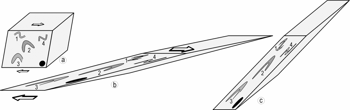
A comparison of the distribution patterns of lower hemisphere projections reveals that the geometry of different fold groups at mesoscopic scale and that of the regional-scale fold are identical to geometry of outcrop-scale sheath folds (Figs 7, 9, 10). NNE–NE-striking upright axial planes and strongly curvilinear hinge lines are the common geometrical characteristics of all the folds, irrespective of their relative order and scale of development. The regional-scale folds are, therefore, examples of the interference patterns and the sheath folds that were formed during the course of progressive ductile shearing.
5. Kinematic interpretations
5.a. Elliptical folds
Mesoscopic-scale elliptical folds are common in the sheared gneiss–migmatite terrane (Fig. 12a–e). Three-dimensional exposures reveal that the elliptical outcrop patterns are sections through tight to isoclinal, upright and plane-noncylindrical folds. Three alternative mechanisms could be considered for development of the elliptical folds with curvilinear hinge lines: (1) Type 1 interference between the two fold sets (Ramsay, Reference Ramsay1967, pp. 521–5), (2) simultaneous shortening of a layer in different directions during a constrictional deformation (Ramsay & Huber, Reference Ramsay and Huber1983, p. 66), and (3) sheath folding (Carreras, Estrada & White, Reference Carreras, Estrada and White1977; Ramsay, Reference Ramsay1980).
Elliptical outcrop patterns exposed on sections normal to the longest axes of sheath folds. Approximately isoclinal nature and the cats-eye geometry of elliptical folds are noteworthy. (a, b, e) Granite gneiss; (c, d) migmatized-biotite schist. White arrow in (c) points to a σ-shaped quartz megacryst in the mylonite.

That the elliptical folds do not represent a Type 1 interference pattern is apparent from two lines of evidence: (1) lack of two sets of axial planes at high angle to each other and, (2) lack of such arrays of ellipses that contain two sets of axial traces paralleling major and minor axes of successive ellipses (e.g. fig. 10–6 in Ramsay, Reference Ramsay1967, p. 525). The alternative mechanism of constrictional deformation is also ruled out because of the consistency in orientation of the axial surface of elliptical folds. The folds developed in a constrictional deformation are typically inconsistent with respect to the axial plane orientation (Ghosh & Ramberg, Reference Ghosh and Ramberg1968).
The ubiquity of shear structures such as the mylonite foliation, the S–C fabric and the rotated asymmetrical megacrysts implies that the entire gneiss–migmatite terrane is extensively sheared (Fig. 13a). As many folds and interference structures are demonstrably confined within the mesoscopic-scale ductile shear zones, it is evident that these structures were developed during the course of a progressive ductile shearing (Fig. 13b, c). The occurrence of elliptical folds in a setting of intense ductile shearing implies that these structures are the two-dimensional sections of sheath folds.
(a) σ-shaped asymmetrical megacrysts in the granite gneiss mylonite. (b) Occurrence of an isoclinal fold (indicated by arrow) within a dextral ductile shear zone in the granite gneiss. (c) Type 3 interference pattern confined within a ductile shear zone in the granite gneiss. Arrow points to the hinge zone of early fold in the interference pattern.

The geometry of elliptical folds is an indicator of the type of bulk strain prevalent during the development of sheath folds (Alsop & Holdsworth, Reference Alsop and Holdsworth2006). The shapes of elliptical cross-sections, that is, sections normal to the longest axis of the sheath, that develop in simple shear, general shear and constrictional types of bulk strains are characteristically analogous-eye-fold, cats-eye-fold and bulls-eye-fold, respectively (Alsop & Holdsworth, Reference Alsop and Holdsworth2006). The axial ratio of the outermost ellipse, a, is equal to, less than, and greater than the axial ratio of the innermost ellipse, b, in the sheath folds that are developed in simple shear, general shear and constrictional strain regimes, respectively (Fig. 14).
Cartesian plot for shape representation of elliptical folds and determination of nature of bulk strain (after Alsop & Holdsworth, Reference Alsop and Holdsworth2006). Cats-eye shape of most elliptical folds suggests a general shear type of bulk strain. R′ = a/b, where a and b are axial ratios of the outermost and the innermost ellipses, respectively, in an elliptical fold.

Geometrical analyses of ten elliptical cross-sections of the sheath folds reveal that the axial ratio of the outermost ellipse is, in general, less than that of the innermost ellipse (average R′ = 0.71 in Fig. 14). Furthermore, the thickness of individual layers along the major axis of the ellipse is 2.2 to 9 times greater than the thickness along the minor axis, and the average ratio of thickness along the major and the minor axes is of the order of 4.6. These geometrical characteristics suggest that most elliptical folds are cats-eye-shaped folds that develop in the general shear, that is, a combination of simple shear and pure shear types of bulk strain (Alsop & Holdsworth, Reference Alsop and Holdsworth2006).
5.b. Deformed lineations
Intersection or striping lineation L 1, though common in the migmatized-biotite schist, is rare or absent in other rocks. Unrolling of the transparent tracings, laid directly over F 2 folds, yields both curvilinear and rectilinear patterns of deformed L 1 lineations (Srivastava, Reference Srivastava2001). Figure 6d illustrates the deformed L 1 lineations over an antiformal upright and isoclinal F 2 sheath fold in the migmatized-biotite schist. The unrolled patterns of deformed L 1 lineation are characteristically rectilinear and V-shaped on the apical zone and the limbs of the sheath fold, respectively. It is noteworthy that most V-patterns are symmetrical about the F 2 hinge line, and the V-patterns become progressively tighter with increase in the plunge angle of the F 2 hinge line.
Based on the theoretical modelling and the natural examples of deformed lineations from the Phulad area, which lies close to the study area in this article, Ghosh, Hazra & Sengupta (Reference Ghosh, Hazra and Sengupta1999) showed that the rectilinear pattern develops when the fold hinge lines are initiated subparallel to the intermediate axis of the strain ellipsoid, whereas the symmetrical V-patterns form when the fold hinge line and lineation are orthogonal and the bulk strain is of general shear type. The common occurrence of the symmetrical V-shaped deformed lineation pattern in the study area, therefore, implies that the F 2 hinge lines were initiated at right angles to the dominant orientation of F 1 hinge lines, at least in some domains, and F 2 sheath folds were developed in a general shear type of bulk strain.
6. Summary and conclusions
Two major fold groups, F 1 and F 2, each containing at least two coaxial fold sets, were developed during progressive ductile shearing in the gneiss–migmatite terrane (Fig. 15a, b). As the fold sets that belong to the same fold group were initiated on a commonly directed hinge line, their interference produced a characteristic Type 3 pattern. By contrast, the non-coaxial refolding of F 1 group folds by F 2 group folds resulted in the development of Type 2 interference pattern at scales ranging from outcrop to map (Fig. 15c). Progressive ductile shearing modified both F 1 and F 2 group folds into sheath folds. Several lines of evidence, such as the variation in attitude of F 1 sheath axial planes and the occurrence of deformed intersection lineation on F 2 sheath folds point to two successive phases of sheath folding during the progressive shearing in the gneiss–migmatite terrane.
Schematic diagrams show the geometrical evolution of F 1 and F 2 group folds and successive sheath folds during progressive shearing. (a) F 1 group folds show coaxial refolding and F 1 sheath folding. (b) F 2 group folds show coaxial refolding and F 2 sheath folding. (c) Progressive folding and refolding of an F 1 sheath by F 2A and F 2B folds, and F 2 sheath folding.

This study proposes that a very large amount of rotation of axial planes and hinge lines during a progressive ductile shearing can impart identical styles to successively developed folds. In a ductile shear zone, successive folds initiate on curvilinear hinge lines because the mylonite foliation that traces these folds is inherently curviplanar (Ghosh, Hazra & Sengupta, Reference Ghosh, Hazra and Sengupta1999). During the progressive ductile shearing, the hinge lines of successive folds become strongly curved, and their limbs and the axial planes assume a near parallelism due to their rotation towards the XY principal plane of the bulk strain ellipsoid (Fig. 11a, b). At a moderate or high magnitude of shear strain, say γ = 3.73, all the folds and the interference patterns, irrespective of their order of development, become extremely tight to isoclinal, strongly noncylindrical and approximately coplanar, except in the very short hinge zones of the late folds (Fig. 11b). The superposition of pure shear on simple shear further tightens the folds and helps achieve the coplanar relationship between successively developed folds (Fig. 11c). It is due to these modifications in fold geometry that several generations of successively developed folds are not only isoclinal, but also approximately coplanar in the intensely sheared gneiss–migmatite terrane.
Several lines of evidence, such as the cats-eye shape of elliptical folds and the symmetrical V-shapes of deformed lineations, imply that ductile shearing occurred in a general shear, that is, simple shear and pure shear, type of bulk strain regime. The occurrence of symmetrical V-shapes of deformed lineations and the orientation of fabric elements further imply that a very large amount of subvertically directed stretching occurred due to intense NNW–SSE-directed horizontal compression in the gneiss–migmatite terrane (Ghosh, Hazra & Sengupta, Reference Ghosh, Hazra and Sengupta1999).
Acknowledgements
I am grateful to Ian Alsop and an anonymous referee for erudite reviews and constructive suggestions. I also thank my students, in particular, Akshay Pradhan, Sanjoy Nag, Jayram Sahoo and Abhijit Bordoloi, who helped map the basement rocks during different phases of the project. Prof. V. Rajamani (JNU) encouraged me to study the basement rocks in Rajasthan. This work was supported by the ‘Deep Continental Studies’ Program of the Department of Science and Technology, Government of India.



