I. INTRODUCTION
In general, electrical conductivity is induced in a polymer coating by dispersing or impregnating carbon black or metal particles as conductive fillers, as is ubiquitous in the coating industry.Reference Njuguna, Pielichowski and Desai1 Additionally, specific polymer coatings such as those constituted from polyaniline or polypyrrole components are intrinsically electrically conducting owing to the π-conjugated nature of the backbone polymeric components. In the context of corrosion-resistant coatings, excellent corrosion-prevention properties have been observed by using polyaniline polymers on steel substrates, and these are thought to be derived from the conducting nature of the polymeric material, which allows for facile charge transfer to the underlying substrate.Reference Rout, Jha, Singh, Bandyopadhyay and Mohanty2
Composite coatings for corrosion prevention are typically constituted from the powder form of carbon blacks or carbon nanotubes/fibers; the latter species are technically challenging to disperse within coatings owing to the intrinsically high Van der Waals attraction among fibers/tubes, which can range up to 1 eV per micrometer of tube–tube contact. In combination with the high surface areas and high aspect ratios of nanotubes/nanofibers, this attraction often leads to significant agglomeration of these otherwise promising candidates that are endowed with desirable mechanical and electrical properties.Reference Iqbal, Narasimhan, Guiheen and Rehg3–Reference Wang, Yang, Banerjee, Herman and Akins5 Consequently, it is imperative to rethink methods for integrating such nanostructured components within coatings and bulk polymer matrices.
Conducting composite coatings have further applications beyond corrosion resistance in structural, packaging, and energy applications. For example, such coatings could potentially be used for charge dissipation during lightning strikes to protect structural parts and for imparting electromagnetic interference (EMI) protection to electronics for packaging applications.Reference Kim, Kim, Lee, Joo, Cho, Yoon, Pejakoviá, Yoo and Epstein6, Reference Chung7 Currently, there is a limited number of alternative materials that can be used to provide barrier and sacrificial corrosion protection to structural parts and pipelines, necessitating huge capital investment for both applications; for instance, the natural gas and oil industries invest heavily in developing materials such as polymer-wrapped glass fiber coatings to protect pipelines against corrosion.Reference Yan, Wang, Han and Ke8 Nevertheless, a small cathodic current needs to be applied to take care of intrinsic defects in these coatings to preclude corrosion initiation.Reference Beavers and Harle9 Speciality polymers with tailored functionalities do not represent a viable solution for these applications (other than packaging) because of cost considerations and difficulties in obtaining the appropriate mechanical, thermal, and barrier properties.
Polymeric coatings on metal substrates have found little practical use in industrial applications for preventing corrosion owing to their overall poor adhesion to underlying substrates.Reference Bellucci, Nicodemo, Monetta, Kloppers and Latanision10–Reference Wielant, Posner, Grundmeier and Terryn13 This is due to lack of molecular compatibility, which gives rise to slippage between the metal and polymer coatings in response to mechanical stresses and can result in catastrophic debonding upon exposure to wet and corrosive environments. Additionally, differential thermal expansion can further accelerate the loss of interfacial adhesion at the polymer/metal interface and give rise to delamination of polymeric coatings.
Additional chemical and physical processing is required to ensure better adhesion of the polymers to metallic substrates. Some examples of such processing include chemical modification to generate metal oxides by thermal, plasma, alkaline, and borate buffer treatment, which provides higher-surface-area irregular surfaces for tethering polymer chains.Reference Wielant, Posner, Grundmeier and Terryn13 Physical treatments used for the same purpose include mechanical polishing and shot blasting to create rough metallic surfaces.Reference Yan, Wang, Han and Ke8 These treatments cause degradation of the metal substrate and can potentially compromise it beyond specifications for technological applications. Chemical treatment creates two additional planar material interfaces, where bonding between each interface may be slightly better than that between the metal and the polymer. Conducting metal oxide–polymer interfaces further permit electrochemical reactions that can give rise to catastrophic cathodic disbonding.Reference Sathiyanarayanan, Azim and Venkatachari14 In the case of insulating oxides, anodically driven deadhesion reactions can take place, causing filiform corrosion. Extensive filiform corrosion, for instance, is commonly observed on aluminum substrates.Reference Romano, Olivier, Nazarov and Thierry15
Currently, researchers are focusing on nanocomposite-hybrid coatings where intimate dispersion of nanomaterials within polymer matrices play a great role in improving tolerance to differential thermal expansion and mitigating electrochemical reactions.Reference Crosby and Lee16 Analogous to the polymer case, nanocomposite coatings are beset by severe adhesion problems due to the formation of suboptimal physical interfaces between nanomaterials, the polymer matrix, and the substrate.Reference Noor and Venneri17
Here we present a novel active–passive approach that seeks to overcome the above-mentioned challenges observed for polymer and nanocomposite coatings using chemically inspired interfacial design and substrate integration of the carbon nanofiber (CNF) material. The CNFs are grown directly onto the low carbon steel (LCS) substrates without any secondary catalysts. Surface-grown nanofibers, hereinafter called integrated nanofibers (INF), serve as cushioning layers for the subsequent polymer layer to lock into their interstices. Densely grown nanofibers appear to be distributed randomly across the substrate surface, and their growth is mediated by both tip and binodal growth mechanisms. Subsequently, a polyetherimide (PEI) layer is used to wet the carbon surface and forms a uniform continuous coating after curing for 1 s at 200 °C in a radiation furnace. Strong interfacial bonding of the novel multicomponent nanocomposite coating prevents corrosive deadhesion from the substrate; the formation of a large passivation layer further significantly decreases corrosion by mediating a charge-transfer reaction. This novel design concept is illustrated using potentiodynamic and impedance measurements. Substantial advantages are derived by using INFs instead of carbon nanotubes in terms of cost, scalability, and potential for environmental impact.
The direct growth of CNFs on a steel substrate surface provides a distributed surface area for the polymer, thereby leading to a stronger chemically compatible interface that can overcome the adhesion problems typically observed between polymers and metal substrates. CNFs have been grown directly on the LCS surface without any catalyst using blast furnace gas as the carbon precursor. The nanofiber-covered surface is then used as a strong adhesion layer for the subsequent attachment of different polymer matrices. INFs can potentially provide for charge dissipation, EMI shielding, and thermal conductivity within a thin polymer coating layer without burdensome processing.Reference Vander Wal and Hall18 Additionally, INFs with an infused PEI polymeric layer provide dramatically enhanced corrosion protection to steel with remarkable passivation observed upon exposure to 3.5% NaCl electrolyte solution.
The advantages offered by this approach are that (i) the nanofibers require no purification from the catalyst as the process does not use any extraneous catalyst species, (ii) excellent dispersion is readily achieved within the polymer because the CNFs are already present on the steel surface as a film, (iii) the nanofibers do not have to be handled in powder form wherein they represent an inhalation hazard,Reference Zhu, Chang, Dai and Hong19 (iv) functionalization of nanofiber surfaces is avoided by mitigating the need for oxidizing acids that can introduce defects,Reference Hill, Lin, Qu, Kitaygorodskiy, Connell, Allard and Sun20 and (v) strong adhesion to the steel substrate is obtained since the nanofibers grow directly from the substrate at high temperatures. This method thus provides distinct advantages over the conventional industrial practice of separating and purifying CNFs by using concentrated acids, which can potentially severely damage the fiber sidewalls and degrade the mechanical and electronic properties, while also being labor and energy-intensive and generating large quantities of hazardous waste.Reference Govindaraj and Rao21, Reference Talapatra, Kar, Pal, Vajtai, Ci, Victor, Shaijumon, Kaur, Nalamasu and Ajayan22 The stable dispersion of nanofibers within polymer matrices is an essential criterion for effective and strong load transfer between the CNFs and the polymer matrix such that the filler can induce the desired strength improvements; consequently, our approach avoids high shear mixing and chemical modification steps that have thus far had very limited success and have yet to allow the full potential of carbon nanotubes and nanofibers to be realized within coatings.Reference Thostenson, Ren and Chou23, Reference Fenouillot, Cassagnau and Majesté24 In other words, the novel direct growth protocol developed here offers unique advantages for using CNFs to reinforce polymeric materials and for incorporating CNFs directly within the host polymer matrix.
II. EXPERIMENTAL SECTION
A. Fabrication of integrated carbon nanofibers
CNF arrays were grown by the thermal decomposition of CO/CO2 over a Fe-substrate in the temperature range of 600–750 °C. The growth parameters were optimized to obtain dense arrays of CNFs with uniform diameter. Gas compositions of H2 (15%), CO (68%), and CO2 (17%) were used in the study. A steel substrate with a thickness of 0.67 mm and nominal composition of 0.1% C, 1.5% Mn, 0.2% Si, 40 ppm N, 0.01% P, 0.002% S, 0.003% Ti, and the rest Fe was chosen for the investigation. Samples were cut into plates with dimensions of 3 cm × 3 cm, and were placed on a quartz plate in a glass tube equipped with discrete inlets and outlets for the gas mixture. The glass tube was heated to the requisite temperature in the oven. The gas outlet was further connected to an online gas chromatograph (Varian GC model 3700, Agilent, Middelburg, The Netherlands) equipped with a 15m Q-Plot column, which enabled the direct measurement of outlet gas concentrations. The substrate surface was first reduced with a H2/N2 gas mixture at a total flow rate of 100 mL/min. Subsequently, CNFs were synthesized using a gas mixture containing CO/CO2 with a flow rate of 500 mL/min. Finally, the sample was cooled to room temperature under an argon atmosphere. The amount of carbon formed on the steel substrate was quantified by measuring the increase in weight caused by the formation of CNFs.
B. Deposition of polymer layer
The polyimide liquid resin (the precursor was a polyamic acid formed by condensation of pyromellitic dianhydride and oxydianiline) was applied to the INF-coated substrates by using laboratory roll coater methods, followed by curing at 250 °C for 5 min.
C. Coating characterization
The morphological features of the as-prepared fibers and composite coatings were examined by scanning electron microscopy (SEM) using a LEO 1550 FEG-SEM (Carl Zeiss SMT, Oberkochen, Germany) equipped with an Inlens detector. FTIR analyses were performed using a Perkin Elmer Spectrum 100 instrument (Waltham, MA).
D. Electrochemical interface characterization
The electrochemical characteristics of the coatings were evaluated at a scanning rate of 1.67 mV/s using potentiodynamic measurement techniques performed on a Solatron 1280C (Hampshire, UK) test system. A 3.5% NaCl electrolyte solution was used for the electrochemical measurements with calomel and platinum used as the reference and counter electrodes, respectively. Electrochemical impedance was measured after exposure to a 3.5% aqueous NaCl solution for varying periods of time; to understand the corrosion behavior of the coating from an electrochemical perspective, an equivalent circuit model was developed, which takes into account the various layers and interfaces of the substrate and the coating as well as the electrolyte solution for the different circuit components. The electrical circuit elements have been derived using a Bode plot, which plots the modulus of the impedance versus the frequency. Given the complexity of the system, the extracted coating capacitances are likely to be accurate only within an order of magnitude. Nevertheless, the observation of low coating capacitance (Cc = 1/|Z| at log ω = 0, f → 0.16 Hz) values is taken as an indication that the applied coating serves as an efficacious diffusion barrier against corrosive ions and water at the applied voltage range of 10 mV in the frequency range between 0.001 and 65 kHz, which represents the most relevant regime for predictive studies of corrosion. The difference in the impedance plots of the nanocomposite PEI–INF coatings versus that of as-cast polymeric PEI coatings is strikingly apparent. Corrosive deadhesion behavior of the coating was evaluated by using salt spray testing methods as per ASTM B117.
Electrical conductivity measurements were performed for the samples using the four-point probe method to account for contact resistances.
III. RESULTS AND DISCUSSIONS
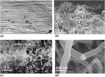
To generate the nanofibers on the LCS substrate, the substrate is first cleaned in an alkaline bath, followed by surface conditioning in presence of hydrogen and then subjected to thermal chemical vapor depositionReference Dai25, Reference Baddour, Fadlallah, Nasuhoglu, Mitra, Vandsburger and Meunier26 using blast furnace gas as the carbon precursor. Figures 1(a) and 1(b) show top-view high-resolution scanning electron microscopy images of a bare LCS surface and the surface after growth of CNFs, respectively. A scotch-tape test (ASTM D3359) to evaluate the strength of adhesion of the grown INFs to the iron-substrate surface reveals strong adhesion between the as-grown nanofibers and the underlying steel substrate. No debonding or delamination of the INF is observed upon peeling the scotch tape by the specified method. Transmission electron microscopic analysis shows that the grown INFs range in length from ∼1 to 25 μm with significant remnant catalyst particles at the ends. It is worth noting that no extraneous catalyst is added to the system and that the detected catalyst particles exclusively originate from the iron substrate. Average inner and outer diameters of the INFs are 15.9 ± 3.5 and 32.9 ± 6.6 nm, respectively.
(a) Top-view scanning electron microscopy (SEM) image of untreated low carbon steel (LCS), (b) top-view SEM image of carbon nanofibers (CNFs) grown upon the surface, (c) cross-sectional SEM image showing random growth of CNFs on the surface, and (d) cross-sectional SEM image illustrating bimodal growth of CNFs with an isolated “Fe” particle in between two hollow carbon fibers.

The catalyst impurities would likely have an effect on measured electrical and thermal properties. Iron particles at the tip of nanofibers confirm the operation of a tip growth mechanism [Fig. 1(c)] and also indicate some bimodal growth [cross-sectional view, Fig. 1(d)]. At the high temperatures used in this reaction, it is likely that metallic iron(0) clusters segregate from the dopants and surface oxides to form catalytically active islands. Dissolution and subsequent supersaturation of blast furnace gases within the catalytically active particles give rise to a carbon–iron eutectic. Subsequently, CNFs and multiwalled nanotubes crystallize from the particles through a vapor–solid mechanism as a result of the continuing supersaturation at the catalytic metal particles.Reference Kolasinski27, Reference Huang, White, Sfeir, Huang, Huang, Wind, Hone and O’Brien28 The relative polydispersity of catalytic sites gives rise to wide variations in diameter and morphology of the obtained nanofibers. The cross-sectional SEM image shown in Fig. 1(d) confirms the densification of the nanofibers on the LCS substrate.
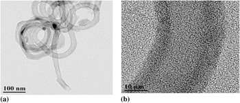
Transmission electron microscopy confirms the random growth of nanofibers with well-defined walls and inner channels (Fig. 2). These images further confirm that the fibers are hollow and flexible without fracture. It has been observed from several studies that dispersing CNFs in polymeric media confers several advantages including significant improvement in elastic modulus, breaking stress, and storage modulus as well as enhanced thermal robustness of the polymer composite.Reference Wise, Park, Siochi and Harrison29 Notably, however, others have drawn different conclusions and have suggested that the inherent large-scale disorder common to all nanocomposites, irrespective of the level of dispersion, inevitably degrades mechanical properties compared to idealized predictions that take into account more ordered architectures.Reference Schaefer and Justice30 This important caveat must be considered while defining expectations for the mechanical properties of nanocomposite coatings.
(a) Transmission electron microscopy structure of CNFs after removal from the surface, showing hollow fibers with well-defined inner walls and (b) intermediate graphitic/crystalline structures obtained using CO/CO2 as the carbon source for the growth of integrated nanofibers.

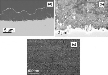
In this study, we have primarily examined the ability of the CNFs to provide corrosion protection to the underlying steel substrate in saline environments in conjunction with the PEI host matrix. An ∼3-μm thick PEI film is cast onto the INFs using a facile laboratory chemcoater process, which is readily scalable to industrial levels. The PEI layer is observed to spread over CNFs without any evidence of air pockets or bubbles, indicating full penetration of the polymer in the interstices between the nanofibers and suggesting good wettability between the nanofibers and the overcoated PEI layer. The microstructure of polymer-coated CNFs [Figs. 3(a)–3(c)] shows a rough coating surface with the polymer layer conformably adhering to the CNFs and penetrating inside the voids between the CNFs. The cross-sectional SEM image in Fig. 3 shows that polymer-coated CNFs appear to be in intimate contact with each other. Closer examination of Fig. 3(b) reveals the absence of even crack separation between the polymer and CNFs, with the CNFs appearing to cleanly span the gap between the metal and the polymer. No dangling CNFs are observed corroborating the strong attachment of the CNFs to both the underlying steel substrate and the overcoated PEI polymeric layer.
(a) SEM image of the polymer layer overcoating the INFs (cross-sectional view) before exposure to a corrosive electrolyte solution, (b) SEM image at higher magnification showing the top view of the integrated INF/polymer film, and (c) dense solid homogeneous coating illustrating a single matrix

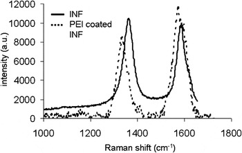
It is difficult to peel off the polymer from the CNF surface indicating strong interfacial interactions and excellent chemical compatibility between the PEI and the CNFs, which likely is derived from the strong π–π interactions between the aromatic groups of the polymer and the CNFs. The Raman spectra of INF–PEI showed a notable downshift in the peak positions of the D and G bands compared to that of INF-coated steel, which is a clear evidence of strong interactions between PEI and INF (Fig. 4). It is likely that the enmeshment of the INFs within the polymer matrix gives rise to tensile stresses on the nanofibers, as required for load transfer. Note that the G band is the in-plane tangential mode corresponding to C–C bond vibrations and is thus sensitive to stresses imposed upon the nanofibers as well as to charge-transfer doping as a result of interactions with the polymeric matrix. The downshifting of the Raman bands likely represents the softening of the nanofiber phonon modes due to load transfer. Indeed, the generated stresses rather than electronic effects contribute preponderantly to the observed softening of the nanofiber Raman modes.
Raman spectra of PEI-coated INF-grown steel exhibiting a pronounced downshift of the “D” band. The observed shift is likely a combination of the doping of the CNFs and tensile strain. Charge transfer from the polymer matrix to the nanofiber can cause softening of the nanofiber phonon modes, and tensile strain created due to evaporation of the solvent after chemcoating the polymer layer can further exacerbate this softening of the characteristic vibrational modes.

Studies have shown that highly aromatic polyimides can interact with the sidewalls of carbon nanotubes via strong π–π stacking interactions.Reference Wise, Park, Siochi and Harrison29, Reference Yang, Chen, Chen, Li, Zhang, Xu and Yi31 Furthermore, the structural similarities between the CNFs and the polymer resin provide inherent wettability and chemical compatibility.Reference Mo, Wang, Chen and Yeh32 We submit that such chemically inspired interfacial design is critical to obtain the enhancements in mechanical and corrosion protection properties noted below, albeit given the complexity of the system it is hard to quantitatively elucidate the precise nature of the interface. Nevertheless, it is worth noting that control experiments with INF and other polymers or just the individual components (only PEI or CNFs) do not yield the remarkable corrosion protection (or substrate adhesion) evidenced here, suggesting an appreciable role for the interface. Such a coated system is expected to be especially resistant to microcrack development and propagation. Crack propagation can particularly be hindered by the inclusion of long CNFs. The large surface area of the CNFs provides for remarkable tethering of the polymeric components and is known to dramatically enhance the mechanical interlocking between the polymer and the nanofibers.
Adhesion between the underlying metal substrate and the polymer coating has been illustrated by exposing coated steel sheets to saline environments where the control PEI coating delaminates after 8 days of exposure in the absence of CNFs. The eventual formation of microvoids within PEI provides a route for moisture to penetrate the steel substrate and results in degradation of the coating and corrosion of the underlying substrate. The critical importance of dispersing CNFs within the coating is emphasized by salt spray testing measurements, which indicate that the INF/PEI nanocomposite coatings are stable for greater than 30 days with no evidence for delamination, suggesting that the CNFs provide greater resistance to moisture permeation and delay the development of ion-transport channels (it is worth noting that even truly hydrophobic films inevitably absorb some moisture).Reference Wang, Wang, Kohls, Hamilton and Schaefer33, Reference Wang and Schaefer34 These results have been reproduced over several experimental runs and verify that the system indeed offers very significant corrosion protection, and this protection is maintained under prohesion exposure. The substantially different behavior observed under corrosive environments for the PEI and INF/PEI combinations further corroborates the importance of nanofiber/polymer interactions for imparting corrosion protection.
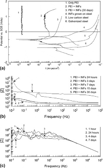
The tremendous protection behavior of CNFs has further been quantitatively evaluated by using potentiodynamic electrochemical measurements and compared with galvanized steel (zinc-coated LCS) sheets to elucidate their superior characteristics. The results presented in Fig. 5(a) indicate a very appreciable depression in current density from 2–3 × 10⁻² A/cm2 for bare steel to 1–2 × 10⁻⁷ A/cm2 in the case of polymer/INF nanocomposite-coated steel; a large passivation band (−0.225 V to +1.032 V) is observed, which provides clear evidence that the electrochemical reaction at the coating surface is effectively controlled. Note that only the polymer-coated substrate showed insulating barrier properties without any passivation band [as seen in Fig. 5(a)]. The resistance of the INF layer is on the order of 1.0 × 10² Ω/cm2 (as measured by four-point probe resistivity measurements of as-grown nanofibers), whereas an as-cast film of PEI has a sheet resistance >10 MΩ/cm2. The nanocomposite blend has a graded concentration of CNFs at various distances from the substrate but upon establishment of a percolative threshold of the INFs, the composite is found to exhibit conductivity values comparable to those of the as-grown nanofibers.
(a) Potentiodynamic curve showing passivity of polymer-coated INFs on various substrates compared to the behavior of an as-cast polyetherimide (PEI) coating; (b) impedance measurement of polymer + INF coating on a LCS substrate upon saline exposure for varying periods of time; (c) impedance measurement of as-cast polymeric PEI coating on a LCS substrate upon salt spray exposure for varying periods of time.

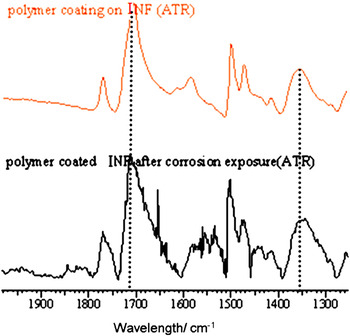
The passivation behavior of CNFs within the nanocomposite polymer matrix is further supported by the impedance measurements depicted in Fig. 5(b); originally, the impedance (|Z|) of the system is on the order of 107 Ohm {coating capacitance (Cc): ca. 0.6 μF/cm2}; however, after 24 h of exposure to the electrolyte, the impedance decreases appreciably to ca. 103 Ohm (Cc: 70 μF/cm2). Subsequently, after 3 days of exposure, the impedance again increases to the order of 105 Ohm (Cc: 3 μF/cm2) and then diminishes again upon exposure to the corrosive solution for 30 days. The impedance measurement in case of the as-cast polymer is shown for comparison in Fig. 5(c); |Z| values decrease with sustained exposure, which is indicative of appreciably greater extent of water permeation and ion transport through the coating into the substrate. (Notably, the polymer layer is delaminated after 10 days of exposure in the absence of the INF adhesion layer, and thus EIS data have not been recorded for time points exceeding this time period.) An important caveat, given the complexity of the systems exposed to real corrosive environments, is that the extracted circuit elements derived from the EIS spectra are likely to be somewhat approximate and valid only within an order of magnitude. The pronounced decrease in the coating capacitance over long exposure times nevertheless suggests that the coating is successful in delaying moisture penetration or ion transport to the surface (especially as compared to the control polymeric coating) and also indicates the operation of charge-transfer reactions at the interface. The complexity of the multicomponent system precludes a more quantitative analysis of the circuit elements, but the variations in impedence upon exposure to corrosive conditions are clearly evident even in the raw data that span several orders of magnitude. FTIR analysis confirms that the PEI–INF composite coating did not deteriorate after exposure for 30 days. Typical peaks of PEI at 1720 and 1360 nm−1 are still observed indicating the retention of the integrity of PEI–INF composite coating (Fig. 6).
FTIR analysis of the PEI-coated INF-grown steel illustrates that even after 30 days of saline exposure, the PEI peaks are clearly apparent. The IR bands at 1720 and 1360 cm−1 show the presence of carbonyl and imide moieties in the five-membered ring structure of PEI, respectively. (color online)

This important observation is further corroborated by the formation of a passivating iron oxide layer below the INFs adjacent to the interface. Rout et al. and Wessling have also evidenced the formation of a passive oxide layer (Fe2O3), which provides corrosion protection.Reference Rout, Jha, Singh, Bandyopadhyay and Mohanty2, Reference Wessling35 The efficacious formation of the passivating layer is likely a result of the nanoscale dimensions and excellent electrical conductivity of the CNFs, which ensure the availability of wide range of active sites to accelerate the formation of a passivating film. The CNFs can act as adsorbents for oxygen molecules owing to their high surface areas, and further being redox-active species they can also readily facilitate reduction of oxygen at the Fe/INF interface. In addition, the positive shift of the corrosion potential indicates that INF coatings exhibit better anti-self-corrosion ability. The presence of iron nanoparticles at the tips of CNFs, as clearly depicted in Figs. 1(c) and 1(d), may help by participating in the passivation reaction. The specific role of the remnant catalyst particles remains to be verified.
IV. CONCLUSIONS
In summary, the novel substrate-integrated nanocomposite concurrently provides remarkable and hitherto never before seen resistance to moisture permeation, almost totally precludes crack propagation, enhances resistance to polymer delamination, and provides significant reduction in current density. This plethora of advantageous properties opens up new avenues for using this novel material for various applications requiring exposure to harsh and corrosive environments. The absence of interfacial separation between the polymer and the metal during saline exposure testing provides clear evidence of the tremendous enhancement in adhesion provided by the incorporation of INFs in the polymer coating. Cross-sectional electron microscopy analysis of metal–CNF–polymer interfaces indicates that CNFs are rooted within the distributed metal surface rather than being confined to a sharp thin boundary layer; furthermore, the polymer penetrates throughout the CNF layer forming a single-phase coating matrix with excellent dispersion of the CNF filler material. In a more general sense, the present system demonstrates novel design concepts of combining substrate integration and dispersion with chemically inspired interfacial design for the fabrication of efficacious multifunctional coatings.
ACKNOWLEDGMENTS
We thank TATA Steel Europe research and development microstructural analysis group. We thank Prof. Leon Lefforts from University of Twente for technical discussions.