




1. Introduction
Solutions of the rotating shallow water equations (rSWE hereafter), linearised about a state of rest in the presence of a large-scale potential vorticity gradient, provide textbook illustrations of the fundamental wave motions in the ocean (and atmosphere). Standard textbook treatments (e.g. Gill Reference Gill1982; Pedlosky Reference Pedlosky1987; Vallis Reference Vallis2006; Paldor, Rubin & Mariano Reference Paldor, Rubin and Mariano2007), naturally assume a flat or uniformly sloping ocean bottom, and proceed to obtain the dispersion relations of the waves in question, namely Rossby, Poincaré and Kelvin waves. Here, the question of how these dispersion relations are modified in the presence of finite topography, with horizontal scale much smaller than the wavelength of the waves in question, is addressed in detail using the method of homogenisation. The aim is to provide some quantitative insight into the extent to which variable ocean bathymetry can cause wave propagation speeds to differ from predictions based on the average ocean depth, with a view to providing guidance to ocean model developers as to the general importance of accurate parameterisation of bottom roughness, at least as far as accurately representing the propagation of large-scale waves is concerned.
We aim to connect with and extend two important bodies of work. The first concerns the non-rotating problem, in which the linear rSWE reduce to the classical wave equation. Topography enters the problem as a variable local wave speed  $c=\sqrt {gh}$ (
 $g$ gravity,
 $h$ ocean depth), and to determine the effective speed
 $c_{eff}$ of long waves in the presence of variations in
 $c$ is a classical problem in the mathematics of homogenisation, in its essence equivalent to that first formulated by Rayleigh (Reference Rayleigh1892) for the heat equation. Modern analysis of homogenisation problems (see e.g. the reviews of Nandakumaran (Reference Nandakumaran2007), Allaire (Reference Allaire2012) and Mei & Vernescu (Reference Mei and Vernescu2010), § 5.5) reveals that, using
 $\langle \cdot \rangle$ to denote a horizontal average,
 $\langle c^{-2} \rangle ^{-2} \le c_{eff}^{2} \le \langle c^{2} \rangle$, i.e. for any small-scale bathymetry the square of the effective long wave speed
 $c_{eff}$ is bounded below by the harmonic mean of
 $c^{2}$ (in the elasticity literature the Reuss bound) and above by its arithmetic mean (the Voigt bound). Equivalently, the effective ocean depth
 $H_{eff}$ ‘felt’ by the long waves satisfies
 $\langle h^{-1} \rangle ^{-1} \le H_{eff} \le \langle h \rangle$. Notably, the lower (harmonic mean or Reuss) bound is actually attained for propagation over one-dimensional topography (e.g. Rosales & Papanicolaou Reference Rosales and Papanicolaou1983; Hu & Chan Reference Hu and Chan2005), (see also Holmes (Reference Holmes2012), for an introductory treatment) meaning that the simple approximation of using the averaged depth
 $\langle h \rangle$ in place of
 $H_{eff}$ will certainly result in large modelling errors for waves propagating over steep ocean ridges. For two-dimensional topography
 $H_{eff}$ lies somewhere between the two bounds, and one aim here is to quantify its exact dependence on topographic height and area fraction for some idealised two-dimensional topographies, in particular arrays of periodic cylinders for which highly accurate asymptotic solutions exist (e.g. Balagurov & Kashin Reference Balagurov and Kashin2001; Godin Reference Godin2013). Another key question is how the classical wave equation analysis is modified by the introduction of rotation, i.e. are Poincaré and Kelvin waves affected to the same extent as non-rotating gravity waves?
The second key body of work concerns the quasi-geostrophic limit of the rSWE. Here solutions of the homogenisation problem formulated by Rhines & Bretherton (Reference Rhines and Bretherton1973), applied to both sparse random topographies and (possibly densely packed) periodic arrays (Benilov Reference Benilov2000; Vanneste Reference Vanneste2000a,Reference Vannesteb), give insight into the extent to which Rossby wave propagation is affected by small-scale topography. Compared with the gravity wave case, the physics is relatively complicated, as the long Rossby waves of interest can interact resonantly with trapped topographic Rossby waves attached to each seamount (see e.g. Jansons & Johnson Reference Jansons and Johnson1988). In the absence of regularising dissipative processes, such as Ekman friction, the modified Rossby wave dispersion relations feature singularities at the resonant frequencies. These quasi-geostrophic results are naturally restricted to topography satisfying the requirements of quasi-geostrophic scaling, i.e. ocean depth variations must satisfy  $|h-\langle h \rangle | / \langle h \rangle \ll 1$, and the horizontal scale of the topography must be sufficiently large that the Rossby number of the motion remains small (see discussion below). The present treatment, in the full rSWE, relaxes these assumptions and extends the previous results to finite topographies including islands. Not only is an assessment of the wider validity of the quasi-geostrophic results made possible, but also a quantitative comparison between the relative effect of the topography on the different wave types (Rossby, Kelvin and Poincaré) can be made.
It is important to emphasise that the focus here is on waves which are long relative to the topographic length scale. The homogenisation technique and related multiple-scale methods can be adapted to study the behaviour of waves with wavelengths comparable to the topography, a situation which allows for phenomena such as Bragg resonance between surface gravity waves and periodic topography (e.g. Mei Reference Mei1985; Naciri & Mei Reference Naciri and Mei1988). Similarly, Bühler & Holmes-Cerfon (Reference Bühler and Holmes-Cerfon2011) and Li & Mei (Reference Li and Mei2014) have considered the effect of bathymetry on internal tides in a stratified ocean, and have quantified the damping effect of a random topographic distribution at leading order in amplitude. As a consequence, the results presented here do not constitute a complete picture, and shorter waves can be expected to exhibit a distinct and rich phenomenology.
The paper is organised as follows. In § 2 the method of homogenisation is introduced and applied to the linearised rSWE to obtain the homogenised governing equations. The coefficients in these governing equations are determined from the solution of so-called cell problems, defined on the short length scale, which are formulated explicitly for the rSWE. The quasi-geostrophic and non-rotating limits of the governing equations and cell problems are then considered, making the connection to previous results clear. In § 3 the case of periodic arrays of seamounts arranged in a regular square lattice is treated in detail. Particular attention is given to cylindrical seamounts, because the multipole expansion method of e.g. Balagurov & Kashin (Reference Balagurov and Kashin2001) and Godin (Reference Godin2013) can be used in this case to obtain highly accurate asymptotic solutions to the cell problems, including the new ‘rotating’ cell problem which arises from the rSWE. The outcome is various means to determine the topographically induced corrections to the dispersion relations of Kelvin, Poincaré and Rossby waves, including an explicit formula valid for Rossby waves in the presence of finite amplitude topography, complementing the quasi-geostrophic results of Benilov (Reference Benilov2000) and Vanneste (Reference Vanneste2000b). In § 4 the case of well-separated randomly distributed seamounts is considered, with seamount height, radius and density determined by a prescribed distribution. Again, the goal is to determine the corrections to the wave dispersion relations. In § 5 conclusions are drawn.
2. Homogenisation of the linear rSWE
2.1. The non-dimensional equations and multiple scales approach
The two-dimensional rSWE, in dimensional form and linearised about a state of rest, are
 \begin{equation} \left.\begin{gathered} \boldsymbol{u}_t + f \boldsymbol{k} \times \boldsymbol{u} ={-} g \boldsymbol{\nabla} \eta, \\ \eta_t + \boldsymbol{\nabla}\boldsymbol{\cdot} (h \boldsymbol{u}) = 0. \end{gathered}\right\} \end{equation}
Here,  $ \boldsymbol {u}$ is the horizontal velocity and
 $\eta$ the free-surface displacement,
 $ \boldsymbol {k}$ is the unit vector in the vertical direction,
 $h$ is the depth of the undisturbed ocean which varies on a horizontal scale
 $l$ due to the presence of bottom topography,
 $f=f_0+\beta y$ is the local Coriolis parameter, with
 $\beta$ denoting the Rossby parameter, and
 $g$ is the acceleration due to gravity.
In order to apply asymptotic analysis consistently, it is convenient to work with non-dimensional equations. It will be assumed in all that follows that  $l \ll L, L_\beta$, where
 $L=\sqrt {gH_0}/f_0$ is the Rossby radius and
 $L_\beta =f_0/\beta$ is the length scale associated with the planetary vorticity gradient. Since our interest here is in waves with wavelength longer than
 $l$, it is convenient to take the Rossby radius
 $L$ as our horizontal scale, and to treat the non-dimensional parameter
 $b=L/L_\beta$ as order unity. Choosing a time scale
 $f_0^{-1}$, a velocity scale
 $U$, and free-surface displacement scale
 $f_0 U L /g$, the non-dimensional equations are found to be
 \begin{equation} \left.\begin{gathered} \boldsymbol{u}_t + (1+ b y) \boldsymbol{k} \times \boldsymbol{u} ={-} \boldsymbol{\nabla} \eta, \\ \eta_t + \boldsymbol{\nabla}\boldsymbol{\cdot} (h \boldsymbol{u}) = 0. \end{gathered}\right\} \end{equation}
For ease of notation in (2.2), the same variable names have been retained as for their dimensional counterparts in (2.1). Notice that the velocity scale  $U$ in the treatment above is arbitrary, except that it must be sufficiently small for the linear equations to remain valid.
Below, we will also make use of the linear potential vorticity (PV) equation, which follows from (2.2) by taking the curl of the momentum equation and then substituting in the continuity equation
 \begin{equation} \frac{1}{h} \frac{\partial}{\partial t} \left( \zeta - \frac{(1+by) \eta}{h} \right) + \boldsymbol{u} \boldsymbol{\cdot}\boldsymbol{\nabla} \left( \frac{1+by}{h} \right) = 0,\end{equation}
where  $\zeta = \boldsymbol {k} \boldsymbol {\cdot }\boldsymbol {\nabla } \times \boldsymbol {u}$ is the relative vorticity.
To exploit the horizontal scale separation between the topography and the length scales of the waves of interest, a small parameter  $\varepsilon = l / L \ll 1$ can now be introduced. To permit multiple-scale analysis, the spatial variable
 $ \boldsymbol {X}= \boldsymbol {x}/ \varepsilon$ can be defined, which describes spatial variations on the scale of the topography. Importantly, we treat
 $ \boldsymbol {x}$ and
 $ \boldsymbol {X}$ as independent variables in the following analysis. In general, the topography
 $h( \boldsymbol {X}, \boldsymbol {x})$ can also be allowed to vary on the long length scale associated with
 $ \boldsymbol {x}$, as would be useful for example to describe a large-scale topographic slope covered in small-scale seamounts.
Next, we introduce an average  $\langle \cdot \rangle$ over the short scales, which can be applied to any function
 $g( \boldsymbol {X}, \boldsymbol {x})$,
 \begin{equation} \langle g \rangle = \frac{1}{|\varOmega|} \int_\varOmega g(\boldsymbol{X},\boldsymbol{x})\,\textrm{d}\boldsymbol{X}. \end{equation}
In the following sections, two main cases will be considered. The first, most tractable case, is that of a regular periodic lattice of seamounts, in which case  $\varOmega$ is a single doubly periodic cell (
 $|\varOmega |$ denotes its area). The second case is that of randomly distributed topography, in which case
 $\varOmega$ can be taken to be a spatial average over a ‘mesoscale’ region which is (asymptotically) intermediate in size between the small and large scales. In the asymptotic limit, the number of mountains in the mesoscale region will tend to infinity, and the mesoscale average will be independent of the particular distribution of the topography and will therefore be equivalent to an ensemble average. The analysis which follows in the rest of this section applies equally in both regimes. Averaged variables will be denoted below by capitals, e.g. applying the spatial average to the topography gives
 \begin{equation} H(\boldsymbol{x})= \langle h(\boldsymbol{X},\boldsymbol{x}) \rangle. \end{equation}
Finally, replacing horizontal derivatives according to the multi-scale formalism, using the chain rule (i.e.  $\boldsymbol {\nabla } \to \varepsilon ^{-1} \boldsymbol {\nabla }_{ \boldsymbol {X}} + \boldsymbol {\nabla }_{ \boldsymbol {x}}$) gives
 \begin{equation} \left.\begin{gathered} \varepsilon \boldsymbol{u}_t + \varepsilon (1+by) \boldsymbol{k} \times \boldsymbol{u} ={-} \boldsymbol{\nabla}_{\boldsymbol{X}} \eta - \varepsilon \boldsymbol{\nabla}_{\boldsymbol{x}} \eta, \\ \varepsilon \eta_t + \boldsymbol{\nabla}_{\boldsymbol{X}} \boldsymbol{\cdot} (h \boldsymbol{u})+ \varepsilon \boldsymbol{\nabla}_{\boldsymbol{x}} \boldsymbol{\cdot} (h \boldsymbol{u}) = 0. \end{gathered}\right\} \end{equation}
The equations (2.6) are the starting point for the analysis to follow.
2.2. The homogenised equations
The large-scale homogenised equations can be obtained from (2.6) by seeking a multiple-scale perturbation solution of the form
 \begin{equation} \left.\begin{gathered} \eta(\boldsymbol{X},\boldsymbol{x},t; \varepsilon) = \eta_0(\boldsymbol{X},\boldsymbol{x},t)+\varepsilon \eta_1(\boldsymbol{X},\boldsymbol{x},t)+\cdots \\ \boldsymbol{u}(\boldsymbol{X},\boldsymbol{x},t; \varepsilon) = \boldsymbol{u}_0(\boldsymbol{X},\boldsymbol{x},t)+\varepsilon \boldsymbol{u}_1(\boldsymbol{X},\boldsymbol{x},t)+\cdots. \end{gathered}\right\} \end{equation}
Inserting (2.7) in (2.6) gives, at leading order
 \begin{equation} \boldsymbol{\nabla}_{\boldsymbol{X}} \eta_0=0,\quad \boldsymbol{\nabla}_{\boldsymbol{X}} \boldsymbol{\cdot} ( h \boldsymbol{u}_0)=0. \end{equation}
From this we deduce that  $\eta _0=\varPi ( \boldsymbol {x},t)$ is independent of the small-scale variable
 $ \boldsymbol {X}$ (i.e.
 $\eta _0=\langle \eta _0\rangle := \varPi$), and that
 \begin{equation} \boldsymbol{u}_0(\boldsymbol{X},\boldsymbol{x},t) = \frac{\boldsymbol{U} H + \boldsymbol{\nabla}^{{\perp}}_{\boldsymbol{X}} \psi}{h}, \end{equation}
where  $\boldsymbol {\nabla }^{\perp }_{ \boldsymbol {X}} \equiv \boldsymbol {k}\times \boldsymbol {\nabla }_{ \boldsymbol {X}}$ is the skew-gradient operator, and
 \begin{equation} \boldsymbol{U}(\boldsymbol{x},t)= \frac{\langle \boldsymbol{u}_0 h \rangle}{\langle h \rangle} \end{equation}
is the depth-weighted average velocity. Here  $\psi ( \boldsymbol {X}, \boldsymbol {x},t)$ is an unknown scalar function to be determined.
Next, applying the averaging operator to the multi-scale equations (2.6), after multiplying the momentum equation by  $h$, gives, at leading order
 \begin{equation} \left.\begin{gathered} \boldsymbol{U}_t + (1+by) \boldsymbol{k} \times \boldsymbol{U} ={-} \boldsymbol{\nabla}_{\boldsymbol{x}} \varPi + \frac{\langle \eta_1 \boldsymbol{\nabla}_{\boldsymbol{X}}h \rangle }{H}, \\ \varPi_{t} + \boldsymbol{\nabla}_{\boldsymbol{x}} \boldsymbol{\cdot} \left( H \boldsymbol{U} \right) = 0. \end{gathered}\right\} \end{equation}
Equations (2.11) govern the evolution of long waves in the presence of topography, except that to close the equations it remains necessary to evaluate the correlation term  $\langle \eta _1 \boldsymbol {\nabla }_{ \boldsymbol {X}}h \rangle$ in terms of the averaged variables
 $ \boldsymbol {U}$,
 $\varPi$ and
 $H$.
To evaluate the correlation term  $\eta _1$ must be determined, and to do so it is necessary to consider the momentum equation of (2.6) at next order. Multiplying by
 $h$ and taking the divergence
 $\boldsymbol {\nabla }_{ \boldsymbol {X}} \boldsymbol {\cdot } (\cdot )$, gives
 \begin{equation} \boldsymbol{\nabla}_{\boldsymbol{X}} \boldsymbol{\cdot} \left( h \boldsymbol{\nabla}_{\boldsymbol{X}} \eta_1 \right) - (1+by) \boldsymbol{\nabla}_{\boldsymbol{X}}^{2} \psi ={-} \boldsymbol{\nabla}_{\boldsymbol{X}} h \boldsymbol{\cdot} \boldsymbol{\nabla}_{\boldsymbol{x}} \varPi. \end{equation}
This is an elliptic equation for  $\eta _1$ which involves the other unknown function
 $\psi$. Evidently another equation is needed to close the system, which can be determined most easily from the PV equation (2.3), which at leading order in
 $\varepsilon$ is
 \begin{align} \boldsymbol{\nabla}_{\boldsymbol{X}} \boldsymbol{\cdot} \left( \frac{\boldsymbol{\nabla}_{\boldsymbol{X}} \psi_t}{h} \right) - (1+by) \boldsymbol{\nabla}_{\boldsymbol{X}} \psi \boldsymbol{\cdot}\boldsymbol{\nabla}_{\boldsymbol{X}}^{{\perp}} \left(\frac{1}{h}\right) ={-} H \left((1+by) \boldsymbol{U} -\boldsymbol{k} \times \boldsymbol{U}_t \right) \boldsymbol{\cdot}\boldsymbol{\nabla}_{\boldsymbol{X}}\left(\frac{1}{h}\right).\end{align}
Notice that (2.12) and (2.13) have both been written with terms involving the unknown  $\psi$ and
 $\eta _1$ on the left, and ‘source’ terms involving
 $h$ and the averaged variables on the right. Before
 $\eta _1$ can be found in terms of the sources from (2.12), (2.13) must first be solved for
 $\psi$. The time dependence in (2.13) is an expected feature, and arises because the rotation adds new physics to the shallow water equations, namely that topography at any horizontal scale will support the motion of trapped topographic Rossby waves (Longuet-Higgins Reference Longuet-Higgins1967; Jansons & Johnson Reference Jansons and Johnson1988). As discussed in the quasi-geostrophic context by Vanneste (Reference Vanneste2000b) and Benilov (Reference Benilov2000), these trapped Rossby waves can be excited resonantly by the large-scale motion.
In general, because (2.12)–(2.13) are linear in  $\psi$ and
 $\eta _1$, the solution for
 $\eta _1$ can be expressed formally using a Green's function approach, in the form of history integral over the past state of the system. This approach, broadly following that of (Vanneste Reference Vanneste2000a), is followed in Appendix B, and results in an integro-differential equation (B6) for the time-evolution of the momentum
 $ \boldsymbol {U}$.
However, our primary interest here is in the impact of the topography on the dispersion relations of periodic waves, therefore solutions  $\propto \exp {(-\textrm {i}\omega t)}$ will henceforth be sought, allowing the substitution
 $\partial _t \to -\textrm {i}\omega$. It follows that (2.13) becomes
 \begin{align} \boldsymbol{\nabla}_{\boldsymbol{X}} \boldsymbol{\cdot} \left( \frac{\boldsymbol{\nabla}_{\boldsymbol{X}} \psi}{h} \right) - \mathrm{i} \frac{1+by}{\omega} \boldsymbol{\nabla}_{\boldsymbol{X}} \psi \boldsymbol{\cdot} \boldsymbol{\nabla}_{\boldsymbol{X}}^{{\perp}}\left(\frac{1}{h}\right) ={-} H \left(\mathrm{i} \frac{1+by}{\omega} \boldsymbol{U}-\boldsymbol{k} \times \boldsymbol{U} \right) \boldsymbol{\cdot}\boldsymbol{\nabla}_{\boldsymbol{X}}\left(\frac{1}{h}\right), \end{align}
and the solution  $\eta _1$ of (2.12) and (2.14) can be expressed as
 \begin{equation} \eta_1 = \boldsymbol{\varPhi} \boldsymbol{\cdot}\boldsymbol{\nabla}_{\boldsymbol{x}} \varPi + H(1+by) \boldsymbol{\varPsi}_{(1+by)/\omega} \cdot \left(\mathrm{i}\frac{1+by}{\omega} \boldsymbol{U} -\boldsymbol{k}\times\boldsymbol{U} \right). \end{equation}
In (2.15) the vectors  $ \boldsymbol {\varPhi }=(\varPhi _1,\varPhi _2)^{\textrm {T}}$ and
 $ \boldsymbol {\varPsi }_\alpha =(\varPsi _{1,\alpha },\varPsi _{2,\alpha })^{\textrm {T}}$ are obtained by solving the so-called ‘cell problems’
 \begin{equation} \boldsymbol{\nabla}_{\boldsymbol{X}}\boldsymbol{\cdot} \left( h \boldsymbol{\nabla}_{\boldsymbol{X}} \varPhi_i \right) ={-} \partial_{X_i} h, \end{equation}
and
 \begin{equation} \left.\begin{gathered} \boldsymbol{\nabla}_{\boldsymbol{X}} \boldsymbol{\cdot} \left( h \boldsymbol{\nabla}_{\boldsymbol{X}} \varPsi_{i,\alpha} \right) = \boldsymbol{\nabla}_{\boldsymbol{X}} ^{2} G_i, \\ \boldsymbol{\nabla}_{\boldsymbol{X}} \boldsymbol{\cdot} \left( \frac{\boldsymbol{\nabla}_{\boldsymbol{X}} G_i}{h} \right) - \textrm{i} \alpha \boldsymbol{\nabla}_{\boldsymbol{X}} G_i \boldsymbol{\cdot} \boldsymbol{\nabla}_{\boldsymbol{X}}^{{\perp}} \left( \frac{1}{h} \right) ={-} \partial_{X_i} \left( \frac{1}{h} \right), \end{gathered}\right\} \end{equation}
respectively, where  $\alpha >0$ is a parameter. The cell problems are elliptic equations defined on
 $\varOmega$, and have unique solutions up to arbitrary functions of the large-scale variables only (see e.g. § 5.3.2 of Holmes Reference Holmes2012). The arbitrary functions can be ignored since they do not contribute to the correlation term in (2.11).
It is important to emphasise that the solutions  $ \boldsymbol {\varPhi }$ and
 $ \boldsymbol {\varPsi }_\alpha$ of the cell problems depend only on the details of the topography, not on the waves being studied or on dynamical parameters such as
 $b$. The first cell problem (2.16) is, for reasons to be explained below, identical to that most commonly arising in classical two-dimensional homogenisation problems of mathematical physics, such as heat transfer through heterogeneous media, the study of which dates back to Rayleigh (Reference Rayleigh1892). The second cell problem (2.17), which is perhaps more accurately described as a one-parameter family of cell problems parametrised by
 $\alpha$, is introduced by the presence of rotation and the associated topographic Rossby waves. An important point is that for real
 $\alpha$,
 $ \boldsymbol {\varPsi }_\alpha = \boldsymbol {\varPsi }_{-\alpha }^{*}$, as can be seen by making the substitutions
 $\alpha \rightarrow -\alpha$ and
 $G_i \rightarrow G_i^{*}$ (complex conjugate).
Inserting our expression for  $\eta _1$ from (2.15) leads to
 \begin{align} & -\textrm{i}\omega \left(\boldsymbol{\mathcal{I}} + \left( \frac{1+by}{\omega} \right)^{2} \boldsymbol{\mathcal{K}}_{(1+by)/\omega} \right) \cdot \boldsymbol{U} + \left(1+by \right) \left( \boldsymbol{\mathcal{I}} + \boldsymbol{\mathcal{K}}_{(1+by)/\omega} \right) \cdot \boldsymbol{k} \times\boldsymbol{U} \nonumber\\ &\quad ={-}\left( \boldsymbol{\mathcal{I}} + \boldsymbol{\mathcal{D}} \right) \boldsymbol{\cdot}\boldsymbol{\nabla}_{\boldsymbol{x}}\varPi, \end{align}
where  $ \boldsymbol {\mathcal {I}}$ is the identity matrix and the matrices
 $ \boldsymbol {\mathcal {D}}$ and
 $ \boldsymbol {\mathcal {K}}_\alpha$ are given by
 \begin{equation}
\boldsymbol{\mathcal{D}} ={-}\frac{1}{H}
\left(\begin{array}{@{}cc@{}} \langle \varPhi_1 \partial_{X_1} h
\rangle & \langle \varPhi_2 \partial_{X_1} h \rangle \\
\langle \varPhi_1 \partial_{X_2} h \rangle & \langle
\varPhi_2 \partial_{X_2} h \rangle \end{array}\right),\quad
\boldsymbol{\mathcal{K}}_\alpha = \left(
\begin{array}{@{}cc@{}} \langle \varPsi_{1,\alpha} \partial_{X_1}
h \rangle & \langle \varPsi_{2,\alpha} \partial_{X_1} h
\rangle \\ \langle \varPsi_{1,\alpha} \partial_{X_2} h
\rangle & \langle \varPsi_{2,\alpha} \partial_{X_2} h
\rangle \end{array} \right).
\end{equation}
For cell problems with a fourfold rotational symmetry, for example axisymmetric seamounts arranged in a regular square lattice, these matrices simplify to  $ \boldsymbol {\mathcal {D}}=D \boldsymbol {\mathcal {I}}$ and
 \begin{equation} \boldsymbol{\mathcal{K}}_\alpha=\left(\begin{array}{@{}cc@{}} K_1(\alpha) & -\textrm{i} K_2(\alpha) \\ \textrm{i}K_2(\alpha) & K_1(\alpha) \end{array}\right), \end{equation}
for real, scalar functions  $K_1(\alpha )$ and
 $K_2(\alpha )$, which hereafter we will call the ‘topographic resonance functions’. The cell-averaged linear rSWE then simplify to
 \begin{equation} \left.\begin{gathered} -\textrm{i}\omega \left( 1 + \left( \frac{1+by}{\omega} \right)^{2} K_1 \left(\frac{1+by}{\omega}\right)+ \left( \frac{1+by}{\omega} \right)K_2 \left(\frac{1+by}{\omega}\right) \right) \boldsymbol{U} \\ \quad + (1+by)\left( 1+ K_1\left(\frac{1+by}{\omega}\right)+ \left(\frac{1+by}{\omega} \right)K_2\left(\frac{1+by}{\omega}\right)\right)\boldsymbol{k} \times \boldsymbol{U}\\ ={-}(1+D) \boldsymbol{\nabla}_{\boldsymbol{x}} \varPi, \\ -\textrm{i}\omega\varPi + \boldsymbol{\nabla}_{\boldsymbol{x}} \boldsymbol{\cdot} \left( H \boldsymbol{U} \right) = 0, \end{gathered}\right\} \end{equation}
where again, we emphasise that  $D$,
 $K_1(\alpha )$ and
 $K_2(\alpha )$ are properties of the topography alone.
The system of (2.21) can be solved to obtain expressions determining the dispersion relations of the Poincaré, Kelvin and Rossby waves solutions of the rSWE on the  $\beta$-plane. In §§ 3 and 4 below numerical and analytical results are presented which illustrate the extent to which different topographies affect the dispersion relations of these waves. The results of this section have counterparts when Ekman friction is included in the governing equations, but for simplicity our main focus here is on the frictionless case. However, as in the quasi-geostrophic problem (Vanneste Reference Vanneste2000a,Reference Vannesteb), it is necessary to include a regularising process such as Ekman friction in order to make physical sense of behaviours when there is a resonance between the waves of interest and topographic Rossby waves on the seamounts. Other dissipative processes, such as eddy diffusivity of momentum, could also play a regularising role. Additionally, nonlinearity will also likely act to remove the singularity at the resonances as occurs in the theory of Bragg scattering of water waves (see e.g. the weakly nonlinear analysis of Hara & Mei Reference Hara and Mei1987). Here, following Vanneste (Reference Vanneste2000b), only Ekman friction is considered and in Appendix A the results above are generalised to include this effect. The analogue of the equations (2.21) are shown there to be (A12).
Next, we consider some relevant limits of (2.11) and (2.21).
2.3. Quasi-geostrophic limit of the homogenised equations
The quasi-geostrophic limit of the homogenised equations (2.11) can be obtained by considering the joint limit  $b\ll 1$, in which
 $h=1 - b h_b$, i.e. deviations from a uniform depth of unity are small, and are described by the re-scaled bottom topography
 $h_b( \boldsymbol {X})$ (as for the full system,
 $h_b$ can be allowed to depend on
 $ \boldsymbol {x}$ if required). Time must also be rescaled to the slower timescale
 $T=b t$. Expanding
 \begin{equation} \varPi= \varPi^{(0)}+b \varPi^{(1)}+b^{2} \varPi^{(2)}+\cdots,\quad \boldsymbol{U}=\boldsymbol{U}^{(0)}+ b \boldsymbol{U}^{(1)}+b^{2} \boldsymbol{U}^{(2)} + \cdots, \end{equation}
leads to geostrophic balance at leading order  $-\boldsymbol {\nabla }_{ \boldsymbol {x}}\varPi ^{(0)}= \boldsymbol {k} \times \boldsymbol {U}^{(0)}$ (equivalently
 $ \boldsymbol {U}^{(0)}=\boldsymbol {\nabla }_{ \boldsymbol {x}}^{\perp } \varPi ^{(0)}$), and at next order
 \begin{equation} \left.\begin{gathered} \partial_T \boldsymbol{U}^{(0)} + \boldsymbol{k} \times \boldsymbol{U}^{(1)} + y \boldsymbol{k} \times \boldsymbol{U}^{(0)} ={-} \boldsymbol{\nabla}_{\boldsymbol{x}} \varPi^{(1)} - \langle \eta_1^{(0)} \boldsymbol{\nabla}_{\boldsymbol{X}}h_b \rangle, \\ \partial_T\varPi^{(0)} + \boldsymbol{\nabla}_{\boldsymbol{x}} \boldsymbol{\cdot} \boldsymbol{U}^{(1)} = 0. \end{gathered}\right\} \end{equation}
Applying  $\boldsymbol {\nabla }_{ \boldsymbol {x}}^{\perp } \boldsymbol {\cdot }$ to the momentum equation in (2.23), and using the free-surface displacement equation to eliminate
 $\boldsymbol {\nabla }_{ \boldsymbol {x}} \boldsymbol {\cdot } \boldsymbol {U}^{(1)}$, leads to the quasi-geostrophic potential vorticity equation
 \begin{equation} \partial_T \left( \nabla^{2}_{\boldsymbol{x}} \varPi^{(0)} - \varPi^{(0)} \right) + \varPi_{x}^{(0)} + \boldsymbol{\nabla}_{\boldsymbol{x}} \boldsymbol{\cdot} \langle h_b \boldsymbol{\nabla}^{{\perp}}_{\boldsymbol{X}} \eta_1^{(0)} \rangle = 0. \end{equation}
Here,  $\eta _{1}^{(0)}$ is determined by the leading-order terms in (2.12) and (2.13) which can be simplified to
 \begin{equation} \partial_T \boldsymbol{\nabla}_{\boldsymbol{X}}^{2} \eta_{1}^{(0)} - \boldsymbol{\nabla}_{\boldsymbol{X}} \eta_{1}^{(0)} \boldsymbol{\cdot}\boldsymbol{\nabla}_{\boldsymbol{X}}^{{\perp}} h_b = \boldsymbol{\nabla}_{\boldsymbol{x}} \varPi^{(0)} \boldsymbol{\cdot}\boldsymbol{\nabla}^{{\perp}}_{\boldsymbol{X}}h_b. \end{equation}
Equations (2.24) and (2.25) are the homogenised equations of the quasi-geostrophic system of Vanneste (Reference Vanneste2000a,Reference Vannesteb) in the absence of friction. If we seek solutions  $\propto \exp (-\textrm {i}\varOmega T)$, where
 $\varOmega =\omega /b$ is the frequency on the slow time scale, then the solution
 $\eta _1^{(0)}$ is found from the leading-order terms in (2.15) to be
 \begin{equation} \eta_1^{(0)}=\frac{\textrm{i}}{\varOmega} \tilde{\boldsymbol{\varPsi}}_{1/\varOmega} \boldsymbol{\cdot} \boldsymbol{\nabla_{\boldsymbol{x}}}^{{\perp}} \varPi, \end{equation}
where the vector  $\tilde { \boldsymbol {\varPsi }}_\alpha = \textrm {Re}(\tilde {\varPsi }_{1,\alpha },\tilde {\varPsi }_{2,\alpha })^{\textrm {T}}$ has components which solve the cell problem (2.17) at leading order in
 $b$,
 \begin{equation} \boldsymbol{\nabla}_{\boldsymbol{X}}^{2} \tilde{\varPsi}_{i,\alpha} -\textrm{i} \alpha \boldsymbol{\nabla}_{\boldsymbol{X}}\tilde{\varPsi}_{i,\alpha} \boldsymbol{\cdot}\boldsymbol{\nabla}_{\boldsymbol{X}}^{{\perp}} h_b ={-} \partial_{X_i} h_b.\end{equation}
Focusing on symmetric topography, defining  $\tilde {K}(\alpha )=- \langle \tilde {\varPsi }_{1,\alpha } \partial _{X_1} h_b \rangle$ to be the quasi-geostrophic analogue of
 $K_1(\alpha )$ (the quasi-geostrophic analogue of
 $K_2(\alpha )$ vanishes), and then substituting
 $\varOmega = \omega / b$ allows the eigenvalue equation for the homogenised quasi-geostrophic system to be written as
 \begin{equation} -\textrm{i}\omega \left(1+\frac{b^{2}}{\omega^{2}}\tilde{K} \left(\frac{b}{\omega}\right)\right)\nabla_{\boldsymbol{x}}^{2}\varPi^{(0)}+\textrm{i}\omega \varPi^{(0)}+b\varPi_{x}^{(0)}=0,\end{equation}
recovering the result of Vanneste (Reference Vanneste2000a).
The derivation of (2.24)–(2.28) above differs from that of Vanneste (Reference Vanneste2000a) in a significant way. Here, we have obtained (2.24)–(2.28) by first deriving the homogenised equations (2.11) and then taking the quasi-geostrophic limit, corresponding to the following ordering of the small parameters:  $\varepsilon \ll b \ll 1$. Vanneste, by contrast, applied the homogenisation procedure to the quasi-geostrophic equations themselves, consistent with the ordering
 $b \ll \varepsilon \ll 1$. The fact that the same equations are found in each case gives a clear indication that the result is independent of the value of the ratio
 $\varepsilon / b=l L_\beta / L^{2}$ (where
 $l$ is the topography length scale,
 $L$ is the Rossby radius and
 $L_\beta =f_0/\beta$). In fact, independence of
 $\varepsilon / b$ can be shown more explicitly by a direct asymptotic treatment of (2.6) with
 $\varepsilon \sim b$ (details not given here). In other words, there is no restriction on the topographic length scale
 $l$, beyond the shallow water scaling
 $l \gg H_0$, for (2.24)–(2.25) to hold, a result which extends that of Vanneste, which covers only the case
 $l \gg L^{2} / L_\beta$.
2.4. Non-rotating homogenised equations
To introduce our main results below, it is helpful to first consider (2.11) in the absence of rotation
 \begin{equation} \left.\begin{gathered} \boldsymbol{U}_t ={-} \boldsymbol{\nabla}_{\boldsymbol{x}} \varPi + \frac{\langle \eta_1 \boldsymbol{\nabla}_{\boldsymbol{X}}h \rangle}{H}, \\ \varPi_{t} + \boldsymbol{\nabla}_{\boldsymbol{x}} \boldsymbol{\cdot} \left( H \boldsymbol{U} \right) = 0, \end{gathered}\right\} \end{equation}
where in this case  $\eta _1= \boldsymbol {\varPhi } \boldsymbol {\cdot }\boldsymbol {\nabla }_{ \boldsymbol {x}} \varPi$, with
 $ \boldsymbol {\varPhi }=(\varPhi _1,\varPhi _2)^{\textrm {T}}$, and
 $\varPhi _i$ is determined by the cell problem (2.16). In this case, taking the time derivative of the free-surface equation and substituting for
 $ \boldsymbol {U}_t$ results in the wave equation
 \begin{equation} \varPi_{tt} = \boldsymbol{\nabla}_{\boldsymbol{x}} \boldsymbol{\cdot} \left( H(\boldsymbol{\mathcal{I}} + \boldsymbol{\mathcal{D}} ) \boldsymbol{\cdot}\boldsymbol{\nabla}_{\boldsymbol{x}} \varPi \right), \end{equation}
with  $ \boldsymbol {\mathcal {D}}$ given by (2.19a). The result (2.30) shows that, as expected, shallow water gravity waves obey the wave equation. For symmetric arrays of seamounts with
 $ \boldsymbol {\mathcal {D}}=D \boldsymbol {\mathcal {I}}$, the local gravity wave speed is given by
 $H_{eff}^{1/2}$, where
 $H_{eff}=H(1+D)$ is the non-dimensional effective depth (the dimensional units here being
 $\sqrt {gH_0})$. As discussed in the introduction, functional analysis techniques (e.g. Nandakumaran (Reference Nandakumaran2007), Allaire (Reference Allaire2012) and Mei & Vernescu (Reference Mei and Vernescu2010), § 5.5) applied to (2.30) when
 $ \boldsymbol {\mathcal {D}}=D \boldsymbol {\mathcal {I}}$ reveals the Reuss–Voigt bounds
 $\bar {H}\equiv \langle h^{-1} \rangle ^{-1} \le H_{eff} \le \langle h \rangle \equiv H$, with the lower (harmonic mean or Reuss) bound being attained exactly for propagation over a one-dimensional topography. In § 3.3 below the two-dimensional case is discussed in detail for the case of regular periodic arrays of circular cylinders.
3. The influence of topography on shallow water waves: regular arrays of seamounts
3.1. The  $\beta $-channel dispersion relation in the absence of topography

To set the scene for a quantitative assessment of topographic effects on the dispersion relations, it is helpful to recall the characteristics of Rossby, Kelvin and Poincaré waves in the flat-bottomed case. While (2.21) can be used to investigate wave dispersion in arbitrary domains, including bounded ocean basins and the equatorial  $\beta$-plane, for definiteness we consider a semi-infinite midlatitude
 $\beta$-channel bounded by sidewalls at
 $y=\pm w$, where
 $w$ is the ratio of the half-width of the channel to the Rossby radius. The approach closely follows that of Paldor et al. (Reference Paldor, Rubin and Mariano2007) and Paldor & Sigalov (Reference Paldor and Sigalov2008) to which the reader is referred for more detail. The channel width parameter is set as
 $w=1$ hereafter, because, while it is the case that
 $w$ does affect the branches of the dispersion relation by determining the quantisation of the meridional wavenumber in the channel, varying
 $w$ is found to have a minimal effect on the relative change of each branch due to the topography.
In the absence of topography,  $D=K_i(\alpha )=0$ and
 $H$ is constant in (2.21), and the equations can be simplified by eliminating
 $U$ and
 $\varPi$ to obtain
 \begin{equation} \nabla_{\boldsymbol{x}}^{2} V+\frac{1}{H}\left(\omega^{2}V-(1+by)^{2}V\right)+\textrm{i} \frac{b}{\omega}V_x=0. \end{equation}
Seeking periodic solutions in  $x$ by substituting
 $V(x,y) \to V(y)\ \textrm {e}^{\textrm {i}kx}$ (abusing notation by retaining the variable name
 $V$) gives the Sturm–Liouville problem
 \begin{equation} \frac{{\textrm{d}}^{2} V}{{\textrm{d}y}^{2}}+\left( \frac{\omega^{2}}{H}- k^{2}- \frac{bk}{\omega}-\frac{(1+by)^{2}}{H}\right)V=0,\quad V({\pm} 1)=0. \end{equation}
The problem is standard once the Sturm–Liouville eigenvalues  $\{E_n,\ n=1,2,3\cdots \}$ are identified with
 $E(\omega ,k)=\omega ^{2}/H-k^{2}-bk/\omega$. In general the
 $\{E_n\}$, which since
 $w$ is fixed depend only on
 $b$, can be calculated numerically and the Poincaré and Rossby branches of the dispersion relation follow from finding the roots of the cubic
 \begin{equation} \frac{\omega^{2}}{H}-k^{2}-\frac{bk}{\omega}=E_n(b). \end{equation}
The Kelvin wave, which has  $V=0$ everywhere, is solved for separately and has dispersion relation
 $\omega =\sqrt {H}k$.
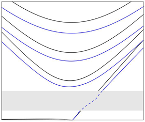
Figure 1 (dotted curves) shows the first three branches of the dispersion relation, obtained from (3.3) after solving (3.2) to obtain  $E_1$,
 $E_2$ and
 $E_3$ using a standard Chebyshev spectral discretisation (e.g. Trefethen (Reference Trefethen2000), 48 points are used), for parameters
 $b=0.5$ and
 $H=0.7135$ (chosen to match the average depth when topography is present). The value of
 $b=0.5$ chosen is larger than that typically obtained from the planetary vorticity gradient in the midlatitude open ocean (
 $b \approx 0.005$) or in the atmosphere (
 $b\approx 0.05$). However, as is well known (e.g. Pedlosky (Reference Pedlosky1987), § 3.10), large-scale gradients in the ocean depth
 $H$ result in a gradient in the PV which also support Rossby wave propagation, and therefore larger values of
 $b$ may be more representative of typical ocean conditions. Regardless, the relative frequency changes due to topography of each branch of the dispersion relation are in fact found to be insensitive to the value of
 $b$.
Dispersion relations for Poincaré, Rossby and Kelvin waves with beta parameter  $b=0.5$, over (black curves) a flat-bottomed ocean of depth
 $H=0.7135$, and (blue curves) a regular array of cylindrical seamounts with
 $h_+=1$,
 $h_-=0.1$ (i.e. cylinder height
 $h_t=h_+-h_-=0.9$) covering area fraction
 $A=1/{\rm \pi}$. Only the first three branches of Poincaré and Rossby waves are shown in panel (a), and panel (b) zooms in to show the Rossby waves more clearly. The dashed blue curve in the resonant frequency band shows the Kelvin wave solution in the extended equations when Ekman friction is present (see text).

It is useful to recall that analytical approximations to the curves in figure 1 are easily obtained in the limit  $b\ll 1$. At leading order in
 $b$ these are (e.g. Paldor et al. Reference Paldor, Rubin and Mariano2007), for Poincaré, Rossby and Kelvin waves respectively,
 \begin{align} \omega_P={\pm}\sqrt{ 1+H \left(k^{2}+n^{2}{\rm \pi}^{2}/4\right)},\quad \omega_R={-}\frac{bkH}{1+H \left(k^{2}+n^{2}{\rm \pi}^{2}/4 \right)},\quad \hbox{and}\quad \omega_K=\sqrt{H}k. \end{align}
Corrections to (3.4a–c) at next order in  $b$ are given in Paldor & Sigalov (Reference Paldor and Sigalov2008).
3.2. The effect of small-scale topography on the dispersion relation: a summary
Next, a summary of results quantifying the effect of small-scale topography on the  $\beta$-channel dispersion relations will be presented and discussed. Details of how the results are actually obtained, by numerical solution of (2.21), are postponed to the sections below. Results will be for regular periodic arrays of cylindrical seamounts, for which the topography is arranged in doubly periodic cells
 $\varOmega$ defined on
 $ \boldsymbol {X} \in (-{\rm \pi} ,{\rm \pi} ] \times (-{\rm \pi} ,{\rm \pi} ]$. The ocean depth is then given by
 \begin{equation} h (\boldsymbol{X}) = \left\{\begin{array}{@{}cc} h_- & |\boldsymbol{X}| \le R \\ h_+ & |\boldsymbol{X}|>R \end{array}\right., \end{equation}
i.e. the cylindrical seamounts have radius  $R$, or cover area fraction
 $A=R^{2}/4{\rm \pi}$, and have height
 $h_t=h_+-h_-$.
First, to give an idea of the extent of the possible impact of small-scale topography, the blue curves in figure 1 show how the dispersion relation is changed in the presence of a rather extreme topography, for which  $h_t=0.9$, i.e. the height of the cylinders is
 $90\,\%$ of the depth of the background ocean (
 $h_+=1$,
 $h_-=0.1$), and the cylinder area fraction is
 $A=1/{\rm \pi}$ (
 $R=2$). The average ocean depth is the same as for the flat-bottomed case (black curves). The main results, summarising the effect of topography on the waves, are as follows: Poincaré waves are slightly slower, typically by around 20 % including near-inertial waves, and Rossby waves are significantly slower, with their phase speed reduced by around 50 %–60 %. The Kelvin wave is slightly faster at small wavenumbers and slower at large wavenumbers, with the two regimes separated by a band of resonant wavenumbers within which Ekman friction effects must be considered to obtain physically reasonable results. The dashed blue curve shows a separate calculation for this region, based on numerical solutions of the extended equations (A12), which include Ekman friction.
To illustrate how the results in figure 1 depend upon the topographic parameters, figure 2 shows the relative change in frequency for a set of representative waves. In (a), the frequency change is shown as a function of area fraction  $A$ (note that
 $A<{\rm \pi} /4$, since
 $A={\rm \pi} /4$ corresponds to the cylinders touching), for the gravest inertial wave (
 $k=0$,
 $n=1$), a representative Poincaré wave (
 $k=5$,
 $n=1$), a relatively short Kelvin wave (
 $k=5$, chosen so that it is outside the resonant frequency band in figure 1), and both short
 $(k=-20)$ and long
 $(k=-2)$ Rossby waves. The topographic height is chosen as
 $h_t=0.5$ (lower than for figure 1 where
 $h_t=0.9$) and the beta parameter as
 $b=0.5$. The results reinforce the impression from figure 1 that Rossby waves are affected much more than Kelvin or Poincaré waves. In fact, the contrast is even greater for the lower topography, because, as will be seen below, Rossby wave corrections are driven by resonances (or near resonances) with topographic Rossby waves on the seamounts, which can have a large effect even for low topography.
The effect of topography on the frequency of various wave types for  $b=0.5$,
 $h_+=1$,
 $h_-=1-h_t$ and cylinder area fraction
 $A$. (a) Frequency change as a function of
 $A$ for fixed topographic height
 $h_t=0.5$. Note that the curves for the inertial, Poincaré and Kelvin waves are near indistinguishable. (b) Frequency change as a function of
 $h_t$ for fixed area fraction
 $A=1/{\rm \pi}$. The shading shows the resonant regions for (I) the short Rossby wave, (II) the long Rossby wave, and (III) the inertial wave (for details see text). In both panels (a,b), curves with open circles show results when Ekman friction is present. These additional solutions are only plotted within and close to the relevant resonant regions.

Panel (b) shows how the results depend on the topographic height  $h_t$. Curves for the six cases shown in (a) are plotted along with three further curves showing calculations with Ekman friction, which are included in order to give some indication of the behaviour in the (shaded) resonant regions. (Region (I) is resonant for the short Rossby wave, region (II) for the long Rossby wave and region (III) for the inertial wave.) The topography-induced change to the frequency for both the short and the long Rossby waves is seen to change sign as the resonant region is traversed, and the Ekman friction calculations give an idea of how the curves join in practice. The value of the Ekman friction
 $r$ is chosen in each case to be close to the minimum required to obtain stable numerical results from (A12) across the resonant region. As seen in the previous panel, Rossby waves are slowed by large-amplitude topography, but here can be seen to be accelerated by small-amplitude topography. Ekman friction, however, suppresses the acceleration at low amplitudes, and has comparatively little effect when the topography is large. The effect on inertial, Poincaré and Kelvin waves is once again relatively small except at extremely large
 $h_t$, when the inertial waves experience resonance and are slowed significantly (when Ekman friction is present).
In summary, all rSWE waves can experience resonance when their frequency approaches that of the trapped topographic Rossby waves, as has been reported for quasi-geostrophic Rossby waves by Vanneste (Reference Vanneste2000a,Reference Vannesteb) and Benilov (Reference Benilov2000). The details vary by wave type. Rossby waves resonate only with relatively low-amplitude topography, and inertial/Poincaré waves only for very large-amplitude topography. Kelvin waves will always experience resonance for some wavenumbers, for any topography supporting trapped waves, because their dispersion relation spans all frequencies.
Next, the calculations necessary to create figures 1 and 2 will be explained.
3.3. The first cell problem and the effective depth
Before an attempt can be made to solve (2.21), it is necessary to first solve the cell problems (2.16) and (2.17) defined on the doubly periodic cell  $\varOmega$. The first of these, (2.16), is of particular interest because its solution allows the effective depth
 $H_\textrm {eff}$ in the non-rotating problem to be determined.
For the case of the periodic array of cylindrical seamounts given by (3.5), (2.16) (dropping the  $i$ index as the problem is now identical up to a rotation for
 $i=1$ and
 $2$) simplifies to
 \begin{equation} \boldsymbol{\nabla}_{\boldsymbol{X}}^{2} \varPhi^{+} = 0, \quad \mbox{and} \quad \boldsymbol{\nabla}_{\boldsymbol{X}}^{2} \varPhi^{-}=0, \end{equation}
where the ‘ $+$’ and ‘
 $-$’ indices correspond to parts of the solution in
 $| \boldsymbol {X}|>R$, and
 $| \boldsymbol {X}|< R$ respectively. The outer solution
 $\varPhi ^{+}$ takes periodic boundary conditions on the edge of
 $\varOmega$. At the cylinder edge, the boundary conditions are
 \begin{equation} \left.\begin{gathered} \varPhi^{+}=\varPhi^{-}, \\ h_+ \partial_\rho \varPhi^{+} -h_- \partial_\rho \varPhi^{-} ={-} \left(h_+{-}h_-\right) \cos{\theta}, \end{gathered}\right\} \end{equation}
on  $| \boldsymbol {X}| = R$, where
 $(\rho ,\theta )$ are the usual polar coordinates for
 $ \boldsymbol {X}$. For further discussion of the cylinder edge boundary conditions see Appendix C.
The cell problem (3.6a,b) and (3.7) is a canonical problem arising in many areas of mathematical physics, most classically heat conduction through a two-dimensional porous medium with cylindrical occlusions (Rayleigh Reference Rayleigh1892; Keller Reference Keller1963; McPhedran, Poladian & Milton Reference McPhedran, Poladian and Milton1988; Balagurov & Kashin Reference Balagurov and Kashin2001) but also in electrostatics and optics (McPhedran & McKenzie Reference McPhedran and McKenzie1980) and in determining dielectric permittivity (Godin Reference Godin2013). Our approach to solving (3.6a,b) and (3.7), closely follows that of Godin (Reference Godin2013), and is based on a multipole expansion which exploits the rapid convergence of the Laurent series of the Weierstrass zeta function. Details are given in Appendix D.
Godin's method (see also Balagurov & Kashin Reference Balagurov and Kashin2001) results in an infinite linear system which must be inverted in order to solve for  $\varPhi ^{+}$ and
 $\varPhi ^{-}$ and thus obtain
 $H_{eff}$ exactly. However, it turns out that truncation of the system at very low order results in a sequence of increasingly accurate Padé approximants to the exact solution. Moreover, at low order these can be easily evaluated, for example the first three are given by
 \begin{equation} \left.\begin{gathered} H_{eff}^{(0)} = h_+ \left( 1- 2\gamma A \right) + O(A^{5/2}), \\ H_{eff}^{(1)} = h_+ \left( \frac{1- \gamma A}{1+\gamma A}\right) + O(A^{9/2}), \\ H_{eff}^{(2)} = h_+ \left( \frac{1-\gamma A-g_4 \gamma^{2} A^{4}}{1+\gamma A-g_4 \gamma^{2} A^{4}}\right)+ O(A^{17/2}). \end{gathered}\right\} \end{equation}
Here,  $A$ is the cylinder area fraction (in our set-up
 $A=R^{2}/4{\rm \pi}$) and
 $\gamma = (h_+-h_-)/(h_++h_-)$, which hereafter will be termed the ‘topography parameter’, as it mediates how the topography influences the effective depth. Notice that
 $-1< \gamma \le 1$, with
 $\gamma =1$ corresponding to an island,
 $\gamma =0$ no topography and
 $\gamma \to -1$ a bottomless pit. For small topography of height
 $h_b$,
 $\gamma \approx h_b/2h_+$. The constant
 $g_4\approx 0.305$ is obtained from the multipole expansion described in detail in Appendix D.
Figure 3 shows the effective depth  $H_{eff}$ for cylinders with height (a)
 $h_t=0.9$ and (b)
 $h_t=0.5$, as a function of the cylinder area fraction
 $A$. Note that the maximum possible area fraction is
 $A={\rm \pi} /4$, when the cylinders touch, and Godin's approach breaks down (Keller (Reference Keller1963), describes the ‘near-touching’ regime). In each case
 $H_\textrm {eff}$ (black circles) is obtained by a numerical calculation in which the linear system is truncated at 24 terms, which is found to be sufficient for convergence to machine precision for all results shown. As anticipated,
 $\bar {H}\le H_{eff} \le H$, i.e.
 $H_{eff}$ in each case is seen to lie within the Reuss–Voigt bounds (dotted grey curves). Also plotted are the approximants
 $H_{eff}^{(0)}$,
 $H_{eff}^{(1)}$ and
 $H_{eff}^{(2)}$, showing that
 $H_{eff}^{(2)}$ gives an excellent approximation to the numerical result right up until the cylinders nearly touch. The zeroth-order approximant
 $H_{eff}^{(0)}$ is accurate for small area fraction, but diverges significantly from the numerical solution at larger
 $A$, and is is seen to violate the Reuss bound. This fact is important in assessing the limitations of results for randomly distributed seamounts in § 4, because the sparse seamount approximation (
 $A \ll 1$) used there turns out to be equivalent to using
 $H_{eff}^{(0)}$ to approximate
 $H_{eff}$. The results (3.8) have been further verified against figure 3 of Hu & Chan (Reference Hu and Chan2005), who plot the refractive index
 $(H/H_{eff})^{1/2}$ for the case of islands (
 $\gamma =1$) as a function of area fraction
 $A$ (see also Mei & Vernescu (Reference Mei and Vernescu2010), § 7.1, for an analogous result for acoustic waves). Excellent agreement is found (results not shown).
Effective depth  $H_{eff}$ (black circles) as a function of cylinder area fraction
 $A$ in the cylindrical array problem with
 $h_+=1$, and topographic heights (a)
 $h_t\equiv h_+-h_-=0.9$ and (b)
 $h_t=0.5$. Also plotted are the approximants
 $H_{eff}^{(i)}$ for
 $i=0,1,2$ (green line, blue line, red line) and the arithmetic (
 $H$)/harmonic (
 $\bar {H}$) mean depths (upper/lower dotted grey lines).

Finally, note that the difference between the effective depth  $H_{eff}$ and the mean depth
 $H$ accounts entirely for the differences between the Poincaré and Kelvin wave dispersion relations at large wavenumber
 $k$ seen in figure 1, because in the large
 $k$ limit these waves do not feel rotation.
3.4. The second (rotating) cell problem
In this section the method used to solve the rotating cell problem (2.17), which is a new feature of the rSWE, is described. Recall that solutions of (2.17) are required in order to evaluate the topographic resonance functions  $K_1(\alpha )$, and
 $K_2(\alpha )$ which appear in (2.21). In the cylindrical seamount case given by (3.5), (2.17) becomes (dropping the
 $i$ index, and focusing on the
 $i=1$ problem, which is sufficient due to symmetry)
 \begin{equation} \nabla_{\boldsymbol{X}}^{2}\varPsi_{\alpha}^{{\pm}}=\nabla_{\boldsymbol{X}}^{2} G^{{\pm}}=0, \end{equation}
with the boundary conditions
 \begin{equation} \left.\begin{gathered} \varPsi_{\alpha}^{+}=\varPsi_{\alpha}^{-},\quad \partial_\theta G^{+}=\partial_\theta G^{-}, \\ h_+\partial_\rho \varPsi_{\alpha}-h_-\partial_\rho \varPsi_{\alpha}= \partial_\rho G^{+}-\partial_\rho G^{-}, \\ \frac{\partial_\rho G^{+}}{h_+}-\frac{\partial_\rho G^{-}}{h_-}-\frac{\textrm{i}\alpha }{R}\left( \frac{\partial_\theta G^{+}}{h_+}-\frac{\partial_\theta G^{-}}{h_-}\right)={-}\left(\frac{1}{h_+}-\frac{1}{h_-}\right)\cos{\theta}, \end{gathered}\right\} \end{equation}
on  $| \boldsymbol {X}|=R$. Here, the notation closely follows that for the non-rotating problem, and detailed derivations of the boundary conditions can be found in Appendix C. Full details of how the multipole expansion method of Godin (Reference Godin2013) is adapted to solve (3.9) and (3.10) are given in Appendix D.
Following the method for  $H_{eff}$ described above, the topographic resonance functions
 $K_1(\alpha )$ and
 $K_2(\alpha )$ are obtained from Godin's method by truncating and solving infinite linear systems, in which
 $\alpha$ appears as a parameter. The lowest-order truncations result in Padé approximants for
 $K_i(\alpha )$, namely
 $K_i^{(0)}$,
 $K_i^{(1)}$ etc., and explicit expressions for the leading three are given in (D23) and (D24).
The convergence of the sequences  $K_{1,2}^{(i)}(\alpha ) \to K_{1,2}(\alpha )$ is, however, more complicated than for
 $H_{eff}^{(i)} \to H_{eff}$ discussed above. To illustrate, figure 4 shows results for
 $i=0,1,2$ (green/blue/red curves) and
 $i=24$ (black circles). The complexity is introduced because the approximant functions
 $K_{1,2}^{(i)}(\alpha )$ each have
 $i$ singularities (for
 $i>1$) in
 $\alpha >1$. In the limit
 $i \to \infty$, there are evidently an infinite number of these singularities, meaning that the ‘true’
 $K_{1,2}(\alpha )$ cannot be described by rational functions of
 $\alpha$. A similar problem, arising in electrostatics and optics, is analysed in McPhedran & McKenzie (Reference McPhedran and McKenzie1980). Adapting their results to the present context, the locations of the singularities
 $\alpha _p$ (in
 $\alpha >0$) are given by the formula
 \begin{equation} \alpha_{p}=\sqrt{\frac{1-\lambda_p\gamma^{2}}{(1-\lambda_p)\gamma^{2}}}, \end{equation}
where  $\lambda _p$ is the
 $p$th eigenvalue of the infinite matrix
 $( \boldsymbol {D} \boldsymbol {E}^{\textrm {T}} \boldsymbol {D})^{2}$, given in Appendix D. Further, it follows that the
 $\alpha _p$ converge to an essential singularity at
 $\alpha _\infty =\lim _{p\to \infty } \alpha _{p}=\gamma ^{-1}$. It turns out that, as is suggested by figure 4, all singularities are confined to a narrow range of
 $\alpha$, which expands slowly as the area fraction increases towards its maximum value. The low-order approximants do a good job away from the resonant band, and as the order increases they capture the location of the leading singularities with increasing accuracy. Physically, the singularities in
 $K_{1,2}(\alpha )$ at
 $\alpha =\alpha _p$ (
 $p\ge 1$) occur due to the excitation of the normal modes of the topographic Rossby waves which propagate around the edges of the cylindrical seamounts (Longuet-Higgins Reference Longuet-Higgins1967; Jansons & Johnson Reference Jansons and Johnson1988; Benilov Reference Benilov2000; Vanneste Reference Vanneste2000a). That the singularities all occur in
 $\alpha >1$ is related to the topographic Rossby waves frequencies being bounded above by the inertial frequency. If a large-scale wave has a frequency which matches the frequency of one of these normal modes, a resonant excitation will occur which requires Ekman friction or another form of dissipation to regularise. The structure of the streamfunction of the first three normal modes is shown in figure 5. In practice, if a small amount of friction is added to the system, the effect of the higher modes is negligible compared with the first mode, due to the weak correlation between their fine-scale structure and that of the topography itself. Panels (c) and (d) in figure 4 show how
 $K_{1,2}(\alpha )$ depend on the area fraction of the topography, for fixed
 $\alpha =1.45$. The resonant band is seen to be located around
 $A\approx 0.64$.
Values of  $K_{1,2}^{(i)}(\alpha )$ plotted as functions of
 $\alpha$ and
 $A$. The low-order Padé approximants (
 $i=0,1,2$) are shown with green, blue, and red lines respectively, and the ‘true’ Padé approximants (
 $i=24$) are shown with circles. To give an idea of the convergence, only the main solution branches are plotted for each curve, e.g. in panel (a) the ‘true’
 $K_1$ has an infinite number of singularities in
 $1.2 \lesssim \alpha \lesssim 1.5$, which would be impossible to plot. The topographic height is fixed at
 $h_t=0.9$, the area fraction and
 $\alpha$ are fixed at
 $A=49/25{\rm \pi}$, and
 $\alpha =1.45$ in panels (a,b) and panels (c,d) respectively.

Spatial structure of the first three normal modes of the topographic array, illustrated by contouring  $G_R=\textrm {Re}\lbrace \psi \rbrace$. The cylindrical seamounts have radius
 $R=2$ (area fraction
 $A=1/{\rm \pi}$) and height
 $h_t\equiv h_+-h_-=0.9$.

In summary, the convergence issues with the functions  $K_i(\alpha )$ present difficulties for the numerical solution of (2.21). Consequently, solutions of (2.21) are treated as valid only if no singularities of
 $K_i( (1+by) / \omega )$ are present within the computational domain. This condition defines the ‘resonant regions’ in figures 1 and 2) (or, strictly speaking, the non-resonant region). Solutions given within the resonant regions use the extended system (A12) to include Ekman friction, and are therefore regularised.
3.5. Numerical solution of (2.21)
Once the functions  $K_1(\alpha )$ and
 $K_2(\alpha )$ are found to the required accuracy, (2.21) can be solved numerically. The numerical method used is as follows. First, solutions
 $\propto \exp (\textrm {i}kx)$ are sought for fixed wavenumber
 $k$, reducing the system to a first-order system of ordinary differential equations in the
 $y$-variable, defined on the interval
 $[-1,1]$. This system is suited to a Chebyshev spectral method (e.g. Trefethen Reference Trefethen2000), in which the
 $y$-grid is discretised into
 $N+1$ points (
 $N=96$ is used) located at the zeros of the Chebyshev polynomial of order
 $N+1$. Standard techniques allow the differentiation matrix
 $ \boldsymbol {\mathcal {D}}_y$ to be obtained for the grid, which, for the flat-bottomed case with
 $K_1(\alpha )=K_2(\alpha )=D=0$. allow the discretised version of (2.21) to be written as a generalised eigenvalue problem of the form
 \begin{equation} -\textrm{i}\omega \boldsymbol{A}\boldsymbol{v}+\boldsymbol{B}\boldsymbol{v}=0, \end{equation}
where  $ \boldsymbol {v}=(U_1,\ldots ,U_{N+1},V_2,\ldots ,V_N,\varPi _1,\ldots ,\varPi _{N+1})^{\textrm {T}}$, and
 $ \boldsymbol {A}, \boldsymbol {B}$ are square block matrices of size
 $3N+1$. Note that the discretised
 $V$-equation spans only the interior Chebyshev points, with the block matrices being adjusted accordingly, in order that the boundary conditions
 $V(\pm 1)=0$ are satisfied. The values of
 $\omega$ and
 $ \boldsymbol {v}$ satisfying (3.12) can then be found using standard numerical eigenvalue routines.
When topography is present the matrices  $ \boldsymbol {A}$ and
 $ \boldsymbol {B}$ in (3.12) themselves depend on
 $\omega$, through the arguments of
 $K_1(\cdot )$ and
 $K_2(\cdot )$, and the method above must be adapted. Our approach is to use a fixed-point iteration method, by writing
 \begin{equation} -\textrm{i}\omega_{n} \boldsymbol{A}\left(\omega_{n-1}\right)\boldsymbol{v}_{n}+\boldsymbol{B}\left(\omega_{n-1}\right)\boldsymbol{v}_{n}=0, \end{equation}
for iteration  $n$, and using the flat-bottomed frequency for the initial guess
 $\omega _0$. The idea is that repeated solution of (3.13) will lead to the convergence of
 $\omega _n$ and
 $ \boldsymbol {v}_{n}$ to the desired solutions
 $\omega$ and
 $ \boldsymbol {v}$. While basic, this method works well in the sense that analogues of all flat-bottomed solutions can be routinely found using around 20 iterations (for near-machine accuracy), even for extreme topographies.
A further constraint on the numerical solutions is that, once  $\omega$ is known,
 $K_i((1+by)/\omega )$ must be non-singular throughout the domain
 $y \in [-1,1]$. Otherwise a resonance is evidently present, and the numerical solution of (3.13) does not make sense, not least because the discrete grid cannot handle singularities. For each singular point
 $\alpha _p$ of
 $K_i(\alpha )$, all frequencies in the interval
 $\omega \in [(1-b)\alpha _p^{-1},(1+b)\alpha _p^{-1}]$ will have a singularity somewhere in the domain. The resonant frequency band is therefore defined to be the union over all
 $p$ of these intervals. To find meaningful solutions in the resonant frequency band, it is necessary to add finite Ekman friction to the system and solve the resulting extended equations detailed in Appendix A. These Ekman friction calculations have been implemented by the same method, allowing our calculations to be extended into the resonant band.
3.6. Approximate formulae for the dispersion relations
Numerical calculation of the dispersion relation using (2.21) is, as described above, a complicated multi-step process. In practice it is arguably more insightful to have approximate formulae for the topographic effect, for example analogues of the  $b \ll 1$ dispersion relations (3.4a–c) for the flat-bottomed case. It turns out that different approaches to obtain such formulae are necessary for Poincaré and Kelvin waves versus Rossby waves, and each will be considered in turn. It is important to emphasise that the limit
 $b \ll 1$ does not equate to the quasi-geostrophic limit, which also requires the topography to be
 $O(b)$, and that the results in the following two subsections are therefore valid for finite topographies.
3.6.1. Poincaré and Kelvin waves
Consider the limit  $b\ll 1$ in which Poincaré waves and Kelvin waves have frequencies of order unity. (A separate regime in which the Kelvin wave has frequency
 $O(b)$ is not considered here.) In the limit
 $b \ll 1$, the Taylor expansion
 \begin{equation} K_{1,2}\left(\frac{1}{\omega}+b\frac{y}{\omega}\right)=K_{1,2} \left(\frac{1}{\omega}\right)+b\frac{y}{\omega}K_{1,2}'\left(\frac{1}{\omega}\right)+O(b^{2}), \end{equation}
can be used to simplify (2.21), which at leading order in  $b$ becomes
 \begin{align} \left.\begin{gathered} -\textrm{i} \omega\left( 1+\frac{1}{\omega^{2}}K_1\left(\frac{1}{\omega}\right)+ \frac{1}{\omega}K_2\left(\frac{1}{\omega}\right)\right) \boldsymbol{U}+ \left( 1+K_1\left(\frac{1}{\omega}\right)+\frac{1}{\omega}K_2 \left(\frac{1}{\omega}\right)\right)\boldsymbol{k}\times \boldsymbol{U} \\ ={-}\left(1+D\right)\boldsymbol{\nabla_{\boldsymbol{x}}}\varPi, \\ -\textrm{i}\omega \varPi+H\boldsymbol{\nabla_{\boldsymbol{x}}}\boldsymbol{\cdot} \boldsymbol{U} =0, \end{gathered}\right\} \end{align}
with channel wall boundary conditions  $V(\pm 1)=0$. Mathematically, the absence of explicit
 $y$-dependence in (3.15) simplifies matters compared with (2.21), and harmonic wave solutions
 $\propto \exp (\textrm {i} (kx+ly))$ can be sought (we take
 $l=n{\rm \pi} /2$ for ease of comparison with the results above). The result is the following nonlinear equation determining the dispersion relation
 \begin{align} & \left(1-\omega^{2}\right)\left[K_1\left(\frac{1}{\omega} \right)^{2}- \left(\omega+K_2\left(\frac{1}{\omega}\right)\right)^{2}\right] \nonumber\\ &\quad -H_{eff} \left(\omega^{2}+K_1\left(\frac{1}{\omega}\right)+\omega K_2\left(\frac{1}{\omega}\right)\right)\kappa_n^{2}=0, \end{align}
where  $\kappa _n^{2}=k^{2}+n^{2}{\rm \pi} ^{2}/4$. In general, the solution branches of (3.16) must be found numerically using a standard root finding method, although, because it is a single-variable equation, this is evidently much simpler than solving (2.21). For short waves with
 $\omega \gg 1$ (i.e.
 $\kappa _n \gg 1$), the resonance functions
 $K_{1,2}(\alpha )$ can be approximated by their value at
 $\alpha =0$, and using the fact that
 $K_2(0)=0$, the result simplifies further to
 \begin{equation} \omega_P^{2} = \tfrac{1}{2} \left( 1+ \kappa_n^{2} H_{eff} + K_0^{2} \right) + \tfrac{1}{2} \left( (1+ \kappa_n^{2} H_{eff} + K_0^{2})^{2} + 4 K_0^{2}- 4K_0\kappa_n^{2} H_{eff} \right)^{1/2} .\end{equation}
Here,  $H_{eff}$ and
 $K_0\equiv K_1(0)$ are constants determined by the topography which, in the case of regular cylinders, allows for progressively more accurate approximations to be obtained from (3.8) and (D23) respectively. For example, the zeroth-order approximations are
 $H_{eff}=h_+ (1-2\gamma A)$ and
 $K_0=-2\gamma ^{2} A$, which are accurate for low area fraction
 $A$. The result (3.17) can be compared with the flat-bottomed formula (3.4a), which is recovered by setting
 $\gamma = 0$ or
 $A=0$.
For the Kelvin wave it suffices to set  $V=0$ in (3.15) and, following the analysis of the flat-bottomed case, it follows that
 \begin{equation} \omega^{2}+K_1\left(\frac{1}{\omega}\right)+\omega K_2\left(\frac{1}{\omega}\right)= k^{2} H_{eff}. \end{equation}
Once again, this is a nonlinear equation, which must be solved numerically using a root finding method to obtain the Kelvin wave dispersion relation. The short wave result ( $\omega \gg 1$) is
 \begin{equation} \omega_K^{2} = k^{2} H_{eff} - K_0, \end{equation}
which can be compared with (3.4c).
3.6.2. Rossby waves
Rossby waves frequencies are  $O(b)$ in the limit
 $b \ll 1$, therefore to obtain approximate formulae the asymptotic forms of
 $K_1(\alpha )$ and
 $K_2(\alpha )$ are required for
 $\alpha \gg 1$. For the case of the regular array of cylinders they are
 \begin{equation} K_1\left(\alpha\right) =\frac{c_2}{\alpha^{2}}+\frac{c_4}{\alpha^{4}}+ \cdots,\quad K_2\left(\alpha\right) =\frac{d_1}{\alpha}+\frac{d_3}{\alpha^{3}}+ \cdots, \end{equation}
where the sequence of constants  $\{ c_i \}$ and
 $\{ d_i \}$ can be determined to the required accuracy by expanding the formulae in (D23)–(D24). For example, the zeroth-order approximations to the first coefficients are
 $c_2=2A$ and
 $d_1=-2\gamma A$.
Retaining terms in (2.21) up to  $O(b)$, it follows that
 \begin{equation} \left.\begin{gathered} -\textrm{i} \omega \left( 1+c_2 +d_1 \right) \boldsymbol{U}+\left(1+by\right) \left(1+d_1\right)\boldsymbol{k}\times \boldsymbol{U} ={-}\left(1+D\right)\boldsymbol{\nabla_{\boldsymbol{x}}}\varPi, \\ -\textrm{i}\omega \varPi+H\boldsymbol{\nabla_{\boldsymbol{x}}}\boldsymbol{\cdot} \boldsymbol{U} =0. \end{gathered}\right\} \end{equation}
The leading-order Rossby wave dispersion relation is then found to be
 \begin{align} \omega_R &={-}\frac{kb\left(1+d_1\right)H_{eff}}{\left(1+d_1\right)^{2}+(1+c_2+d_1)H_{eff}\kappa_n^{2}}, \nonumber\\ &\approx{-}\frac{kb h_+\left(1-2 \gamma A \right)}{\left(1-2\gamma A\right)+(1+2(1-\gamma)A)\kappa_n^{2} h_+}, \end{align}
where the second expression uses the zeroth-order approximations for  $H_{eff}$,
 $c_2$ and
 $d_1$, which are valid for low area fraction
 $A \ll 1$. The dispersion relation (3.22) can be compared with its flat-bottomed counterpart (3.4b).
Some asymptotic dispersion relations are plotted in figure 6 for a topography with relatively large height ( $h_t=0.9$), and area fraction (
 $A=1/{\rm \pi}$), and at finite
 $b=0.5$, in order to test the validity of the approximations by comparison with numerical solutions of (2.21). Because
 $A$ is relatively large, the second-order approximants are used for
 $H_{eff}$ and
 $K_{1,2}$. Agreement between the full solution of (2.21) and the asymptotics is seen to be good, even at this relatively large value of
 $b$, and further tests with lower values of
 $b$ have confirmed the expected rate of convergence.
Frequency plotted against wavenumber for the Kelvin wave, and the first three modes  $(n=1,2,3)$ of the Rossby waves and Poincaré waves for
 $b=0.5$,
 $h_+=1$ and cylinder height
 $h_t=h_+-h_-=0.9$. Shown here is the full numerical solution to (2.21) (blue lines), and the leading-order asymptotics (3.16)–(3.22), using the approximants
 $H_{eff}^{(2)}$,
 $K_{1,2}^{(2)}(\alpha )$ (black circles). Panel (a) shows the dispersion relations for all three wave types, and panel (b) shows a close-up of the Rossby waves.

3.7. Quasi-geostrophic regime
In this section our focus is the quasi-geostrophic regime which, as discussed in § 2.3 above, requires not only  $b\ll 1$, as in the preceding sections, but also
 $O(b)$ topography. Writing
 $h_t=bh_b$, and applying the methods described above to (2.28) results in the following nonlinear equation for the Rossby wave dispersion relation for the scaled frequency
 $\varOmega =\omega /b$,
 \begin{equation} \varOmega+\frac{k}{1+\kappa_n^{2}}+\frac{\kappa_n^{2}}{\varOmega(1+\kappa_n^{2})} \tilde{K}\left(\frac{1}{\varOmega}\right)=0. \end{equation}
The function  $\tilde {K}(\alpha )$ is defined using the solution of the quasi-geostrophic cell problem (2.27), and is the quasi-geostrophic analogue of
 $K_1$ (
 $K_2 \to 0$ in the quasi-geostrophic limit). The first three approximants are given by (D25). Using the zeroth-order approximant in (3.23) recovers the dispersion relation found in Vanneste (Reference Vanneste2000b) and Benilov (Reference Benilov2000) for widely separated seamounts. The use of more accurate approximants for
 $\tilde {K}$ in (D25) therefore extends these previous results to the case of more densely packed regular topography.
It is interesting that the quasi-geostrophic limit results in a qualitatively different formula (3.23) for the Rossby wave dispersion relation compared with the finite topography limit (3.22). Specifically, the quasi-geostrophic formula allows for the possibility of resonant behaviour, while the finite topography formula involves just a quantitative modification of the flat-bottomed formula. The explanation is that the finite topography,  $b\ll 1$ limit excludes resonance because the long Rossby wave frequency becomes
 $O(b)$ while the trapped topographic Rossby waves retain
 $O(1)$ frequency. In the quasi-geostrophic limit, by contrast, both the long waves and the trapped waves have
 $O(b)$ frequency, and therefore resonance remains possible.
To investigate the regimes of validity of the quasi-geostrophic and finite topography approximations, figure 7 compares the calculated frequencies to those of the full rSWE, obtained from numerical solutions of (2.21). The comparison is for  $b=0.1$, and a topography of regular periodic cylinders across the full range of topographic heights
 $h_t$, with cylinder area fraction
 $A=1/{\rm \pi}$. In the full system resonance is found to occur when
 $h_t$ is around 0.04 to 0.06, which can be regularised with e.g. Ekman friction. The quasi-geostrophic formula (3.23) captures the full dispersion curve behaviour quite accurately close to the resonance, while the finite topography result (3.22) evidently does not. As the topography amplitude is increased beyond
 $h_t \approx 0.3$, however, the quasi-geostrophic approximation is increasingly inaccurate, and the finite topography result captures the full rSWE behaviour well. In practice, therefore, each approximation has its own domain of validity.
Rossby wave frequency against topographic depth for a fixed wavenumber  $(k,l)=(-{\rm \pi} /2,{\rm \pi} /2)$,
 $b=0.1$ and area fraction
 $1/{\rm \pi}$. Shown are the full numerical solution (black curves), the finite topography approximation calculated using
 $K_{1,2}^{(2)}(\alpha )$ (red circles), and the quasi-geostrophic approximation calculated using
 $\tilde {K}^{(2)}(\alpha )$ (blue circles). The shaded region indicates the range of frequencies which are prohibited by resonance, and the numerical solution including friction
 $(r=0.17)$ is included, joining the two solution regions.

4. Randomly distributed seamounts
The regular periodic seamounts covered in the previous section have the advantage that the rSWE dispersion relations can be calculated accurately for arbitrary seamount height  $h_t$ and area coverage
 $A$. However, with respect to the ocean this ‘regular array’ topography is obviously artificial. In particular, resonance effects will be unduly amplified, because the topographic Rossby wave at every seamount (at the same latitude
 $y$) has the same frequency. It is evidently worthwhile to compare the results above with those for a randomised topography in which seamount location, height and radius are governed by a specified distribution. The drawback of considering a randomised distribution, as shown previously in the quasi-geostrophic case (Benilov Reference Benilov2000; Vanneste Reference Vanneste2000b), is that in order for the problem to be tractable an assumption of widely separated seamounts must be made, i.e. the area fraction
 $A \ll 1$. As will be shown, this approximation turns out to be equivalent to using the zeroth-order approximants
 $H_{eff}^{(0)}$,
 $K_i^{(0)}$ for the effective depth and topographic resonance functions which, as can be seen in figure 3 and figure 4, become inaccurate at finite
 $A$.
To examine the effect of randomly distributed seamounts the averaging operator (2.4) needs careful interpretation. The region  $\varOmega =\varOmega ( \boldsymbol {x})$ formally becomes a region centred on
 $ \boldsymbol {x}$ that is asymptotically intermediate in scale between the large and small length scales. In this asymptotic regime, for a suitable randomly generated field
 $g$ in (2.4), the averaged field
 $\langle g \rangle$ will be independent of the details of
 $\varOmega$. In practice, it is not straightforward to make calculations with (2.4) unless the function
 $g$ can be linearly decomposed into contributions from each mountain in
 $\varOmega$, i.e. interactions between mountains can be neglected so that (suppressing
 $\boldsymbol {x}$-dependency)
 \begin{equation} g(\boldsymbol{X}) \approx \sum_{i=1}^{N} g_1( \boldsymbol{X}- \boldsymbol{X}_i, R_i, \gamma_i ), \end{equation}
where  $\boldsymbol {X}_i$ is the location of the
 $i$th mountain, and
 $g_1( \boldsymbol {X}, R, \gamma )$ is the contribution to
 $g$ from a single seamount of radius
 $R$ and topography parameter
 $\gamma$ at the origin. Inserting (4.1) into (2.4), and exploiting the fact the region
 $\varOmega$ is large, allows the joint limit
 $N\to \infty$,
 $\varOmega \to \infty$ to be taken. A number density
 $n(R, \gamma )$ can now be introduced, defined so that the number of seamounts with radius
 $\in [R,R+ \textrm {d}R)$ and topography parameter
 $\in [\gamma ,\gamma + \textrm {d}\gamma )$ in a small area
 $\textrm {d} \boldsymbol {X}$ is
 $n(R,\gamma ) \,\textrm {d}R \,\textrm {d} \gamma \, \textrm {d} \boldsymbol {X}$. This allows the sum in (4.1) to be replaced with integrals in (2.4), which can each be centred on the origin by change of variables so that
 \begin{equation} \langle g \rangle =\int_{{-}1}^{1} \int_0^{\infty} \int_{\mathbb{R}^{2}} g_1(\boldsymbol{X} , R, \gamma ) n(R,\gamma)\,\textrm{d}\boldsymbol{X}\,\textrm{d}R \, \textrm{d}\gamma. \end{equation}
Next, consider the averaging operator (4.2) as applied to (2.19a,b) to determine  $H_\textrm {eff}$ for the case of cylindrical topography distributed according to
 $n(R,\gamma )$. The first cell problem (3.6a,b) and (3.7) is greatly simplified compared with the doubly periodic case, as it need only be solved in
 $\mathbb {R}^{2}$, using standard polar coordinates. The solution (
 $\varPhi^+=\gamma R^{2} \cos {\theta }/\rho$,
 $\varPhi^-=\gamma \rho \cos {\theta }$) is equal to the zeroth-order solution for seamounts in the doubly periodic domain given in appendix D.1. In other words, the zeroth-order small
 $R$ approximation in the doubly periodic case and the non-interacting seamount approximation in (4.1) are equivalent. Inserting the solutions into (2.19a) gives
 \begin{equation} H_{eff} = h_+ \left( 1- 2 \int_{{-}1}^{1} \int_0^{\infty} {\rm \pi}R^{2} \gamma n(R,\gamma) \,\textrm{d}R \, \textrm{d}\gamma \right). \end{equation}
The expression (4.3) for  $H_{eff}$ simplifies further if it is assumed that
 $n(R,\gamma )$ is separable, i.e.
 \begin{equation} n(R,\gamma)=\frac{A}{a_0} p_R(R) p_\gamma(\gamma), \end{equation}
where  $A \ll 1$ is the area fraction covered by seamounts as above,
 $a_0=\int _0^{\infty } {\rm \pi}R^{2} p_R(R) \, \textrm {d}R$ is the average seamount area,
 $p_R(R)$ is the probability density function of the cylinder radii and
 $p_\gamma (\gamma )$ is the probability density function of the height parameter. In this case
 \begin{equation} H_{eff} = h_+ \left( 1- 2 A \int_{{-}1}^{1} \gamma p_\gamma(\gamma) \,\textrm{d}\gamma \right), \end{equation}
from which the zeroth-order doubly periodic result in (3.8) is recovered, independently of the choice of  $p_R(R)$, by setting the heights of all cylinders to be equal, i.e.
 $p_\gamma (\gamma )=\delta (\gamma -\gamma _0)$ for constant
 $\gamma _0$.
The topographic resonance functions can be calculated similarly, and the results are
 \begin{equation} \left.\begin{gathered} K_1(\alpha) ={-} \int_{{-}1}^{1} \int_0^{\infty} \frac{2 {\rm \pi}R^{2} \gamma^{2}}{1-\alpha^{2} \gamma^{2}} n(R,\gamma) \,\textrm{d}R \, \textrm{d}\gamma \left( ={-} 2 A \int_{{-}1}^{1} \frac{\gamma^{2} p_\gamma(\gamma)}{1-\alpha^{2} \gamma^{2}} \,\textrm{d}\gamma \right) \\ K_2(\alpha) =\alpha \int_{{-}1}^{1} \int_0^{\infty} \frac{2 {\rm \pi}R^{2} \gamma^{3}}{1-\alpha^{2} \gamma^{2}} n(R,\gamma) \,\textrm{d}R \,\textrm{d}\gamma \left( = 2 \alpha A \int_{{-}1}^{1} \frac{\gamma^{3} p_\gamma(\gamma)}{1-\alpha^{2} \gamma^{2}} \textrm{d}\gamma \right). \end{gathered}\right\} \end{equation}
The terms in brackets show the results for the separable case, which reduce the zeroth-order expressions in (D23) and (D24) for seamounts of constant height.
The results (4.3)–(4.6) allow (2.21) to be solved numerically using the methods of § 3 above. It is also possible to obtain analytical results by exploiting the smallness of  $A$, employing a regular expansion for the frequency of the form
 \begin{equation} \omega=\omega_0+A\omega_1+O(A^{2}), \end{equation}
and thereby obtaining the leading-order corrections to the dispersion relations (cf. Vanneste (Reference Vanneste2000b), for the quasi-geostrophic case). Details will be given in Goldsmith's thesis. Here, we present numerical results for cylindrical seamounts which are uniformly distributed in height, with the depth over the seamounts in the range  $h_{min}< h_-< h_\textrm {max}$, and with a separable number density (4.4). This situation corresponds to
 \begin{equation} p_\gamma(\gamma)=\left\{\begin{array}{@{}cc} \dfrac{\left(1+\gamma_+\right)\left(1+\gamma_-\right)}{\left(\gamma_+{-}\gamma_-\right)} \dfrac{1}{(\gamma+1)^{2}} & \gamma_- < \gamma < \gamma_+ \\ 0 & \hbox{otherwise} \end{array}\right. , \end{equation}
where  $\gamma _-=(h_+-h_{max})/(h_++h_{max})$ and
 $\gamma _+=(h_+-h_{min})/(h_++h_{min})$. Recall that
 $p_R(R)$ is arbitrary in this set-up, because the results depend only on the area fraction
 $A$.
Figure 8 shows results for the distribution (4.8) with  $h_{min}=0.1$ and
 $h_{max}=0.4$, and
 $A=0.1$, which represents a range of tall cylindrical seamounts which, compared with the scenario shown in figure 1 (where
 $A=1/{\rm \pi}$), have a significantly lower area coverage. Qualitatively, the effect of the topography is similar (although weaker) compared to the constant height case nearly everywhere, except close to the resonant region for the Kelvin waves. In the Kelvin wave dispersion relation, singularities are present at
 $\omega =\gamma _\pm$ (dimensionally
 $f_0\gamma _\pm$). It is perhaps surprising that the dispersion relation contains any singularities at all when the heights of the seamounts are distributed, but as shown by Benilov (Reference Benilov2000) for Rossby waves in the quasi-geostrophic case, the integrals in (4.6) result in logarithmic singularities at the endpoints of the distribution at
 $\gamma _\pm$. This translates into logarithmic singularities in the dispersion relations at
 $\omega =\gamma _\pm$, which, much more than the algebraic singularities which occur when the seamount heights are constant, are smoothly regularised by the addition of relatively weak Ekman friction. The dashed blue curve shows the solution of the extended system (A14) with Ekman friction parameter
 $r=0.1$. Further details and discussion of these results will be given in Goldsmith's thesis.
Dispersion relations for mountains distributed according to (4.8) with  $h_{min}=0.1$ and
 $h_{max}=0.4$. The beta parameter
 $b=0.5$ and area coverage
 $A=0.1$. Black curves show the flat-bottomed solution and blue curves show the solution with topography present. The dashed blue curve shows the solution when friction is present, and is plotted only between the two logarithmic resonances, indicated by the dotted lines. Panel (a) shows the dispersion relations for all three wave types, and panel (b) shows a close-up of the Rossby waves.

5. Conclusions
The main results of this work, summarised in figures 1, 2 and 8, show the extent to which finite-amplitude topography can influence Rossby, Kelvin and Poincaré wave speeds compared to the flat-bottomed case. Our results have been presented to illustrate the extent of the error that will necessarily be introduced in ocean general circulation models, due to using the mean ocean depth in place of the fully resolved small-scale topography. Clearly, significant errors in Rossby wave speeds in particular are possible, due either to large-amplitude topography with significant area coverage, or due to resonance between the Rossby wave and trapped topographic Rossby waves over seamounts. How significant the latter effect is in the ocean (also for Kelvin waves) remains an open question. Certainly the impact of resonance is reduced, although not removed entirely, by using a distribution of topographic heights in place of topography with a single height. Another reason resonance may not be so important in practice is that, as noted in the conclusions of Vanneste (Reference Vanneste2000b), in the typical ocean situation the frequency of the trapped topographic Rossby waves will usually be higher than that of the propagating Rossby waves, meaning the topography will not resonate but will act to slow the Rossby wave propagation speed. The corrected dispersion relation (3.22), which quantifies this effect in the finite-amplitude ( $b \ll 1$) regime, gives a useful insight into its magnitude.
The value of the results presented here is not limited to oceanography. The rSWE are used in many other fields, perhaps most relevantly in atmospheric science, where they provide a valuable reduced model describing wave propagation through a stably stratified atmosphere. In this perspective, the ‘topography’ can represent not physical topography per se, but small-scale regions of reduced stratification due to the presence of e.g. distributions of convective clouds. The approach taken here may therefore be of value in quantifying how, for example, equatorial wave speeds are modified by unresolved cloud fields (see also e.g. Biello & Majda Reference Biello and Majda2005), with implications for their parametrisation.
Declaration of interests
The authors report no conflict of interest.
Appendix A. Homogenisation of the rSWE in the presence of Ekman friction
In this section, the analysis of § 2 is repeated for the rSWE with Ekman friction, which in non-dimensional form are
 \begin{equation} \left.\begin{gathered} \boldsymbol{u}_t + (1+ b y) \boldsymbol{k} \times \boldsymbol{u} ={-} \boldsymbol{\nabla} \eta -r\frac{\boldsymbol{u}}{h}, \\ \eta_t + \boldsymbol{\nabla}\boldsymbol{\cdot} (h \boldsymbol{u}) = 0. \end{gathered}\right\} \end{equation}
The Ekman friction parameter is given by  $r=E/f_0H_0$, where
 $E$ is the dimensional Ekman drag coefficient. Following the procedure of § 2, at leading order (2.8a,b) is obtained, and the leading-order surface displacement
 $\varPi$ and velocity
 $ \boldsymbol {u}_0$ can be defined as in the frictionless case. At next order, multiplying the velocity equation by
 $h$ and averaging, results in
 \begin{equation} \left.\begin{gathered} \boldsymbol{U}_t + (1+by) \boldsymbol{k} \times \boldsymbol{U} ={-} \boldsymbol{\nabla}_{\boldsymbol{x}} \varPi -r \frac{\boldsymbol{U}}{\bar{H}}+ \frac{ \langle \eta_1 \nabla_{\boldsymbol{X}}h \rangle }{H}+r \frac{\left\langle\psi\nabla_{\boldsymbol{X}}^{{\perp}}\left(\dfrac{1}{h}\right)\right\rangle}{H}, \\ \varPi_{t} + \boldsymbol{\nabla}_{\boldsymbol{x}} \boldsymbol{\cdot} \left( H \boldsymbol{U} \right) = 0, \end{gathered}\right\} \end{equation}
where  $\bar {H}=\langle h^{-1} \rangle ^{-1}$ is the harmonic mean of the depth. Compared with (2.11) there are two extra terms in (A2), one from the mean drag due to the Ekman friction, and a second correlation term involving
 $\psi$.
The cell problems are then obtained following the methodology of § 2. The analogue of the first cell problem (2.12) is obtained by multiplying the  $O(\varepsilon )$ equation by
 $h$ and taking the divergence, giving
 \begin{align} & \boldsymbol{\nabla}_{\boldsymbol{X}} \boldsymbol{\cdot} \left( h \boldsymbol{\nabla}_{\boldsymbol{X}} \eta_1 \right) - (1+by) \boldsymbol{\nabla}_{\boldsymbol{X}}^{2} \psi-r\nabla_{\boldsymbol{X}}\psi \boldsymbol{\cdot} \nabla_{\boldsymbol{X}}^{{\perp}} \left(\frac{1}{h}\right) \nonumber\\ &\quad ={-}\boldsymbol{\nabla}_{\boldsymbol{X}} h \boldsymbol{\cdot} \boldsymbol{\nabla}_{\boldsymbol{x}} \varPi-rH\boldsymbol{U}\boldsymbol{\cdot} \nabla_{\boldsymbol{X}}\left(\frac{1}{h}\right). \end{align}
The second cell problem determining  $\psi$ follows from the potential vorticity equation, which at leading order in
 $r$ is given by
 \begin{align} & \boldsymbol{\nabla}_{\boldsymbol{X}} \boldsymbol{\cdot} \left( \frac{\boldsymbol{\nabla}_{\boldsymbol{X}} \psi_t}{h} \right)+r\boldsymbol{\nabla}_{\boldsymbol{X}} \boldsymbol{\cdot} \left( \frac{\boldsymbol{\nabla}_{\boldsymbol{X}} \psi}{h^{2}} \right) - (1+by) \boldsymbol{\nabla}_{\boldsymbol{X}} \psi \boldsymbol{\cdot}\boldsymbol{\nabla}_{\boldsymbol{X}}^{{\perp}} \left(\frac{1}{h}\right) \nonumber\\ &\quad =H \left( \boldsymbol{k} \times \boldsymbol{U}_t -(1+by) \boldsymbol{U} \right) \boldsymbol{\cdot}\boldsymbol{\nabla}_{\boldsymbol{X}}\left(\frac{1}{h}\right) +rH\boldsymbol{k}\times \boldsymbol{U}\boldsymbol{\cdot}\nabla_{\boldsymbol{X}} \left(\frac{1}{h^{2}}\right). \end{align}
Seeking solutions with frequency  $\omega$, and exploiting the linearity of (A3) and (A4), leads to
 \begin{align} \left.\begin{gathered} \eta_1 = \boldsymbol{\varPhi} \boldsymbol{\cdot}\boldsymbol{\nabla}_{\boldsymbol{x}} \varPi +rH\boldsymbol{\varLambda} \boldsymbol{\cdot}\boldsymbol{U}+ H(1+by) \boldsymbol{\varPsi}_{{(1+by)}/{\omega},{r}/{\omega}}\cdot \left(\mathrm{i}\frac{1+by}{\omega} \boldsymbol{U} - \boldsymbol{k}\times\boldsymbol{U}\right) \\ +\textrm{i}\frac{r^{2}H}{\omega}\boldsymbol{\varSigma}_{{(1+by)}/{\omega},{r}/{\omega}}\cdot\boldsymbol{k}\times \boldsymbol{U}, \\ \psi =H\boldsymbol{\varTheta}_{{(1+by)}/{\omega},{r}/{\omega}}\cdot \left(\mathrm{i}\frac{1+by}{\omega} \boldsymbol{U} - \boldsymbol{k}\times\boldsymbol{U}\right)+\textrm{i} \frac{rH}{\omega}\boldsymbol{\varUpsilon}_{{(1+by)}/{\omega},{r}/{\omega}}\cdot \boldsymbol{k}\times\boldsymbol{U}, \end{gathered}\right\} \end{align}
where the vectors  $ \boldsymbol {\varPhi }=(\varPhi _1,\varPhi _2)^{\textrm {T}}$,
 $ \boldsymbol {\varLambda }=(\varLambda _1,\varLambda _2)^{\textrm {T}}$,
 $ \boldsymbol {\varPsi }_{\alpha ,\delta }=(\varPsi _{1,\alpha ,\delta },\varPsi _{2,\alpha ,\delta })^{\textrm {T}}$,
 $ \boldsymbol {\varSigma }_{\alpha ,\delta }=(\varSigma _{1,\alpha ,\delta },\varSigma _{2,\alpha ,\delta })^{\textrm {T}}$,
 $ \boldsymbol {\varTheta }_{\alpha ,\delta }=(\varTheta _{1,\alpha ,\delta },\varTheta _{2,\alpha ,\delta })^{\textrm {T}}$ and
 $ \boldsymbol {\varUpsilon }_{\alpha ,\delta }=(\varUpsilon _{1,\alpha ,\delta },\varUpsilon _{2,\alpha ,\delta })^{\textrm {T}}$ are obtained by solving
 $$\begin{gather} \boldsymbol{\nabla}_{\boldsymbol{X}} \boldsymbol{\cdot} \left( h \nabla_{\boldsymbol{X}}\varPhi_i \right) ={-} \partial_{X_i} h, \end{gather}$$
 $$\begin{gather}\boldsymbol{\nabla}_{\boldsymbol{X}} \boldsymbol{\cdot} \left( h \boldsymbol{\nabla}_{\boldsymbol{X}} \varLambda_i \right) ={-} \partial_{X_i} \left(\frac{1}{h}\right), \end{gather}$$
and
 $$\begin{gather} \boldsymbol{\nabla}_{\boldsymbol{X}} \boldsymbol{\cdot} \left( h \boldsymbol{\nabla}_{\boldsymbol{X}} \varPsi_{i,\alpha,\delta} \right) = \boldsymbol{\nabla}_{\boldsymbol{X}} ^{2} \varTheta_{i,\alpha,\delta}+\frac{\delta}{\alpha}\nabla_{\boldsymbol{X}} \varTheta_{i,\alpha,\delta}\boldsymbol{\cdot} \nabla_{\boldsymbol{X}}^{{\perp}} \left(\frac{1}{h}\right), \end{gather}$$
 $$\begin{gather}\boldsymbol{\nabla}_{\boldsymbol{X}} \boldsymbol{\cdot} \left( h \boldsymbol{\nabla}_{\boldsymbol{X}} \varSigma_{i,\alpha,\delta} \right) = \frac{\alpha}{\delta} \boldsymbol{\nabla}_{\boldsymbol{X}} ^{2} \varUpsilon_{i,\alpha,\delta}+\nabla_{\boldsymbol{X}} \varUpsilon_{i,\alpha,\delta}\boldsymbol{\cdot} \nabla_{\boldsymbol{X}}^{{\perp}} \left(\frac{1}{h}\right), \end{gather}$$
where,
 $$\begin{gather} \nabla_{\boldsymbol{X}}\cdot \left(\frac{\nabla_{\boldsymbol{X}} \varTheta_{i,\alpha,\delta}}{h}\right)+\textrm{i}\delta \nabla_{\boldsymbol{X}}\cdot \left(\frac{\nabla_{\boldsymbol{X}} \varTheta_{i,\alpha,\delta}}{h^{2}}\right)-\textrm{i} \alpha \nabla_{\boldsymbol{X}} \varTheta_{i,\alpha,\delta} \cdot \nabla_{\boldsymbol{X}}^{{\perp}} \left(\frac{1}{h}\right)={-}\partial_{X_i} \left(\frac{1}{h}\right), \end{gather}$$
 $$\begin{gather}\nabla_{\boldsymbol{X}}\cdot \left(\frac{\nabla_{\boldsymbol{X}} \varUpsilon_{i,\alpha,\delta}}{h}\right)+\textrm{i}\delta \nabla_{\boldsymbol{X}}\cdot \left(\frac{\nabla_{\boldsymbol{X}} \varUpsilon_{i,\alpha,\delta}}{h^{2}}\right)-\textrm{i} \alpha \nabla_{\boldsymbol{X}} \varUpsilon_{i,\alpha,\delta} \cdot \nabla_{\boldsymbol{X}}^{{\perp}} \left(\frac{1}{h}\right)=\partial_{X_i}\left(\frac{1}{h^{2}}\right), \end{gather}$$
respectively, where  $\alpha$ and
 $\delta$ are complex parameters. The Ekman friction generalisation of (2.21) therefore requires a pair of two-parameter families of equations to be solved in order to determine
 $\eta _1$ and
 $\psi$. Substituting
 $\eta _1$ and
 $\psi$ into (A2), the generalisation of (2.21) is found to be
 \begin{align} & -\textrm{i}\omega \left( \boldsymbol{\mathcal{I}} + \left( \frac{1+by}{\omega} \right)^{2} \boldsymbol{\mathcal{K}}_{{(1+by)}/{\omega},{r}/{\omega}}+\left(\frac{1+by}{\omega}\right) \frac{r}{\omega}\boldsymbol{\mathcal{M}}_{{(1+by)}/{\omega},{r}/{\omega}} \right) \cdot \boldsymbol{U} \nonumber\\ &\qquad + (1+by)\left( \boldsymbol{\mathcal{I}}+\boldsymbol{\mathcal{K}}_{{(1+by)}/{\omega},{r}/{\omega}}+ \frac{r}{1+by}\boldsymbol{\mathcal{M}}_{{(1+by)}/{\omega},{r}/{\omega}} \right. \nonumber\\ &\qquad \left.-\textrm{i}\frac{r^{2}}{\omega(1+by)}\boldsymbol{\mathcal{N}}_{{(1+by)}/{\omega},{r}/{\omega}}\right) \cdot \left( \boldsymbol{k} \times \boldsymbol{U} \right) \nonumber\\ &\quad ={-}(\boldsymbol{\mathcal{I}}+\boldsymbol{\mathcal{D}}) \boldsymbol{\cdot}\boldsymbol{\nabla}_{\boldsymbol{x}} \varPi-\frac{r}{\bar{H}}\left(\boldsymbol{\mathcal{I}}+\boldsymbol{\mathcal{E}}\right)\cdot \boldsymbol{U}, \end{align}
with the mass conservation equation for  $\varPi$ unchanged. Here,
 $ \boldsymbol {\mathcal {D}}$ and
 $ \boldsymbol {\mathcal {K}}_{\alpha ,\delta }$ are given by (2.19a,b) as before, and the new matrices
 $ \boldsymbol {\mathcal {E}}$,
 $ \boldsymbol {\mathcal {M}}_{\alpha ,\delta }$ and
 $ \boldsymbol {\mathcal {N}}_{\alpha ,\delta }$ have elements
 \begin{equation} \left.\begin{gathered} \left(\boldsymbol{\mathcal{E}}\right)_{ij}={-}\bar{H}\left\langle \varLambda_j\partial_{X_i}h\right\rangle,\quad \left(\boldsymbol{\mathcal{M}}_{\alpha,\delta}\right)_{ij}=\left\langle \varTheta_{j,\alpha,\delta} \partial_{X_i}^{{\perp}}\left(\frac{1}{h}\right)\right\rangle, \\ \hbox{and}\quad \left(\boldsymbol{\mathcal{N}}_{\alpha,\delta}\right)_{ij}= \left\langle \varSigma_{j,\alpha,\delta} \partial_{X_i}h+ \varUpsilon_{j,\alpha,\delta}\partial_{X_i}^{{\perp}}\left(\frac{1}{h}\right)\right\rangle. \end{gathered}\right\} \end{equation}
As in § 2, further simplifications result if it is assumed that the topography has a fourfold symmetry. Details will be given in Goldsmith's thesis.
In the event that the topography is sparse and the Ekman friction is weak, i.e. the topography area fraction  $A \ll 1$ and Ekman friction parameter
 $r \ll 1$, as in the case of randomly distributed seamounts covered in 4, then (A2) can be greatly simplified by retaining only those terms which are leading-order in
 $A$ and
 $r$. The result is
 \begin{equation} \left.\begin{gathered} \boldsymbol{U}_t + (1+by) \boldsymbol{k} \times \boldsymbol{U} ={-} \boldsymbol{\nabla}_{\boldsymbol{x}} \varPi -\frac{r}{h_+}\boldsymbol{U}+ \frac{ \langle \eta_1 \boldsymbol{\nabla}_{\boldsymbol{X}}h \rangle }{h_+}, \\ \varPi_{t} + \boldsymbol{\nabla}_{\boldsymbol{x}}\boldsymbol{\cdot} \left( H \boldsymbol{U} \right) = 0, \end{gathered}\right\} \end{equation}
and Ekman friction can be neglected when determining  $\eta _1$, which is given by (2.15). Equations (A14) are used to calculate the Ekman friction results presented in § 4.
Appendix B. Time-dependent solution to the homogenisation problem
Here the full time-dependent solution to the cell-problem (2.13) is given, and used to obtain the time-dependent generalisation of (2.21), following the approach taken for the quasi-geostrophic system in Vanneste (Reference Vanneste2000a). Starting from a state of rest, the solution to (2.13) is
 \begin{equation} \psi = H \int_0^{t} \boldsymbol{R}(\boldsymbol{X},\boldsymbol{x},t-\tau) \cdot \left((1+by)\boldsymbol{U}(\boldsymbol{x},\tau)-\boldsymbol{k}\times \boldsymbol{U}_t(\boldsymbol{x},\tau)\right)\textrm{d}\tau, \end{equation}
and hence from (2.12),  $\eta _1$ is given by
 \begin{align} \eta_1 &= \boldsymbol{\varPhi}(\boldsymbol{X},\boldsymbol{x})\boldsymbol{\cdot}\boldsymbol{\nabla}_{\boldsymbol{x}}\varPi +H(1+by) \int_0^{t} \boldsymbol{S}(\boldsymbol{X},\boldsymbol{x},t-\tau) \nonumber\\ &\quad \cdot \left( (1+by)\boldsymbol{U}(\boldsymbol{x},\tau)-\boldsymbol{k} \times \boldsymbol{U}_t (\boldsymbol{x},\tau) \right)\textrm{d}\tau. \end{align}
Here,  $ \boldsymbol {R}( \boldsymbol {X}, \boldsymbol {x},t)=(R_1,R_2)^{\textrm {T}}$ and
 $ \boldsymbol {S}( \boldsymbol {X}, \boldsymbol {x},t)=(S_1,S_2)^{\textrm {T}}$ are periodic, zero-mean vectors satisfying the cell problems
 $$\begin{gather} \nabla_{\boldsymbol{X}}\boldsymbol{\cdot}(h\nabla_{\boldsymbol{X}} S_i)=\nabla_{\boldsymbol{X}}^{2}R_i, \end{gather}$$
 $$\begin{gather}\boldsymbol{\nabla}_{\boldsymbol{X}} \boldsymbol{\cdot} \left(\frac{\boldsymbol{\nabla}_{\boldsymbol{X}} R_{it}}{h} \right) - (1+by)\boldsymbol{\nabla}_{\boldsymbol{X}} R_i \boldsymbol{\cdot} \boldsymbol{\nabla}^{{\perp}}_{\boldsymbol{X}} \left(\frac{1}{h}\right)={-}\delta(t)\partial_{X_i}\left(\frac{1}{h}\right), \end{gather}$$
and the initial conditions
 \begin{equation} \boldsymbol{R}(\boldsymbol{X},\boldsymbol{x},0^{-})=\boldsymbol{S}(\boldsymbol{X},\boldsymbol{x},0^{-})=0, \end{equation}
where  $\delta (\cdot )$ is the Dirac delta function. The cell problem (2.16) satisfied by
 $ \boldsymbol {\varPhi }$ remains unchanged.
Using the expression (B2), we can rewrite the momentum equation in (2.11) as an integro-differential equation
 \begin{align} & \boldsymbol{U}_t-(1+by)^{2}\int_0^{t}\boldsymbol{\mathcal{T}}(\boldsymbol{x},t-\tau)\cdot \boldsymbol{U}(\boldsymbol{x},\tau)\,\textrm{d}\tau \nonumber\\ &\qquad +(1+by)\left(\left( \boldsymbol{\mathcal{I}}+\boldsymbol{\mathcal{T}}(\boldsymbol{x},0^{+})\right) \cdot\boldsymbol{k}\times\boldsymbol{U}- \int_0^{t}\boldsymbol{\mathcal{T}}_t(\boldsymbol{x},t-\tau)\cdot \boldsymbol{k}\times\boldsymbol{U}(\boldsymbol{x},\tau)\,\textrm{d}\tau\right) \nonumber\\ &\quad ={-}\left(\boldsymbol{\mathcal{I}}+\boldsymbol{\mathcal{D}}\right)\boldsymbol{\cdot} \boldsymbol{\nabla_{\boldsymbol{x}}}\varPi, \end{align}
where  $ \boldsymbol {\mathcal {T}}$ is the matrix given by
 \begin{equation} \boldsymbol{\mathcal{T}}(\boldsymbol{x},t)=\left(\begin{array}{@{}cc@{}} \left\langle S_1\partial_{X_1}h\right\rangle & \left\langle S_2\partial_{X_1}h\right\rangle \\ \left\langle S_1\partial_{X_2}h\right\rangle & \left\langle S_2\partial_{X_2}h\right\rangle \end{array}\right), \end{equation}
and  $ \boldsymbol {\mathcal {D}}$ is defined as before.
Appendix C. Boundary conditions for discontinuous topography
In this section, the boundary conditions relating to the cell problems (2.16) and (2.17) are derived in detail. Suppose that  $h$ is discontinuous along a closed curve
 $C$ in
 $\varOmega$, then it is necessary to determine the boundary conditions on
 $ \boldsymbol {\varPhi }$,
 $ \boldsymbol {\varPsi }_\alpha$ and
 $G_i$ along
 $C$. Surface displacement must be continuous over
 $C$, and hence from (2.15),
 \begin{equation} \varPhi_i^{+}=\varPhi_i^{-}, \quad \hbox{and}\quad \varPsi_{i,\alpha}^{+}=\varPsi_{i,\alpha}^{-}, \end{equation}
and similarly, since the velocity field must be continuous, (2.9) gives
 \begin{equation} \boldsymbol{n}\cdot \nabla_{\boldsymbol{X}}^{{\perp}} G_i^{+}=\boldsymbol{n}\cdot \nabla_{\boldsymbol{X}}^{{\perp}} G_i^{-}, \end{equation}
where the  $+/-$ superscripts indicate the parts of the solution outside / inside the curve
 $C$, and
 $ \boldsymbol {n}$ is the unit normal vector on
 $C$. The remaining boundary conditions are found from the divergence form of the cell problems
 \begin{equation} \left.\begin{gathered} \nabla_{\boldsymbol{X}}\cdot \left(h\nabla_{\boldsymbol{X}}\varPhi_i+\boldsymbol{e}_i h\right) =0, \\ \nabla_{\boldsymbol{X}}\cdot \left( h\nabla_{\boldsymbol{X}} \varPsi_{i,\alpha}-\nabla_{\boldsymbol{X}} G_i \right) =0,\\ \nabla_{\boldsymbol{X}}\cdot \left( \frac{\nabla_{\boldsymbol{X}} G_i}{h}+\textrm{i} \alpha \frac{\nabla_{\boldsymbol{X}}^{{\perp}} G_i}{h}+\frac{\boldsymbol{e}_i}{h}\right) =0, \end{gathered}\right\} \end{equation}
where  $ \boldsymbol {e}_i$ is the
 $i$th Cartesian basis vector. The arguments of the divergence operator in each case must be continuous across
 $C$, i.e.
 \begin{equation} \left.\begin{gathered} \left[\left(h\nabla_{\boldsymbol{X}}\varPhi_i+\boldsymbol{e}_i h\right)\cdot \boldsymbol{n}\right]_-^{+} =0, \\ \left[\left( h\nabla_{\boldsymbol{X}} \varPsi_{i,\alpha}-\nabla_{\boldsymbol{X}} G_i \right)\cdot \boldsymbol{n} \right]_-^{+} =0, \\ \left[\left( \frac{\nabla_{\boldsymbol{X}} G_i}{h}+\textrm{i} \alpha \frac{\nabla_{\boldsymbol{X}}^{{\perp}} G_i}{h}+ \frac{\boldsymbol{e}_i}{h}\right)\cdot \boldsymbol{n} \right]_-^{+} =0. \end{gathered}\right\} \end{equation}
In the case of the cylindrical topography (3.5), in which  $C$ is a circle centred at the origin with radius
 $R$, only the
 $i=1$ problem need be considered due to rotational symmetry. Dropping the
 $i$ subscript, and focusing on the
 $i=1$ problem, which is sufficient to obtain
 $K_1(\alpha )$ and
 $K_2(\alpha )$, the boundary conditions (C4) become (3.10) given in the main text.
Appendix D. The multipole expansion method
Here the multipole method used to solve the cell problems (3.6a,b)–(3.7) and (3.9)–(3.10) in § 3 is described. The method closely follows that of Godin (Reference Godin2013) (see also Balagurov & Kashin Reference Balagurov and Kashin2001).
First,  $G^{\pm }$ and
 $\varPsi ^{\pm }_\alpha$ in (3.9)–(3.10) are expanded into their real and imaginary parts
 $G^{\pm }=G^{\pm }_R+\textrm {i} G^{\pm }_I$, and
 $\varPsi ^{\pm }_{\alpha }=\varPsi ^{\pm }_{\alpha ,R}+\textrm {i} \varPsi ^{\pm }_{\alpha ,I}$. Next, all real dependent variables are expanded in a complex power series, for example
 \begin{gather} \varPhi^{-}=\mbox{Re}\left\lbrace \sum_{m=0}^{\infty} W_m z^{m}\right\rbrace, \end{gather}
 \begin{gather} \varPhi^{+}=\mbox{Re}\left\lbrace \sum_{m=1}^{\infty} Y_m r_m(z)\right\rbrace, \end{gather}
where  $z=X_1+\textrm {i}X_2$ is the usual complex variable defined on
 $\varOmega$ (recall that the
 $+$ and
 $-$ superscripts refer to solutions in
 $|z|>R$ and
 $|z|< R$ respectively). Expansions for
 $\varPsi _{\alpha ,R}^{-}$,
 $\varPsi _{\alpha ,I}^{-}$,
 $G_R^{-}$ and
 $G_I^{-}$ have the same form as (D1a), with coefficients
 $A_m$,
 $B_m$,
 $F_m$,
 $G_m$ respectively, whereas
 $\varPsi _{\alpha ,R}^{+}$,
 $\varPsi _{\alpha ,I}^{+}$,
 $G_R^{+}$ and
 $G_I^{+}$ have the form of (D1b) with coefficients
 $C_m$,
 $D_m$,
 $M_m$,
 $P_m$. In general all of the coefficients are complex, except for
 $m=0$, when they must be real. The sequence of functions
 $\{ r_m(z) \}$ is given by
 $$\begin{gather} r_1(z) = \zeta(z ; \varLambda) - \zeta( {\rm \pi}; \varLambda) \frac{z}{\rm \pi}, \end{gather}$$
 $$\begin{gather}r_m(z) = \frac{({-}1)^{m-1}}{(m-1)!} \frac{\textrm{d}^{m-1}}{\textrm{d}z^{m-1}} r_1(z),\quad (m>1) \end{gather}$$
with  $r_0(z)$ defined by
 $r_0'(z)=r_1(z)$. Here,
 $\zeta (z ; \varLambda )$ is the Weierstrass zeta function associated with the lattice
 $\varLambda = \{ z_{ \boldsymbol {k}}=2{\rm \pi} (k_x+\textrm {i}k_y) \, | \, { \boldsymbol {k}}=(k_x,k_y) \in \mathbb {Z}^{2} \}$. The advantage of expanding in the functions
 $\{ r_m(z) \}$ is that use can be made of the Laurent expansion of the Weierstrass zeta functions, which for the rectangular lattice
 $\varLambda$ can be written
 \begin{equation} \zeta(z ; \varLambda)= \frac{1}{z} - \sum_{j=1}^{\infty} q_{4j} z^{4j-1}, \end{equation}
where
 \begin{equation} q_j = \sum_{z_{\boldsymbol{k}} \in \varLambda^{*}} \frac{1}{z_{\boldsymbol{k}}^{j}}, \end{equation}
with the sum over the lattice  $\varLambda ^{*}= \varLambda \backslash \{ 0 \}$. The sequence
 $\{ q_{4j},\ j=2,3,\ldots \}$ can be calculated using the recurrence relation
 \begin{equation} q_{4j}=\frac{3}{(4j-1)^{2}(2j-3)}\sum_{l=2}^{2j-2} (4j-2l-1)(2l-1)q_{2l}q_{4j-2l}. \end{equation}
From the above results, and the fact that  $\zeta ({\rm \pi};\varLambda )=\frac {1}{4}$ (Balagurov & Kashin Reference Balagurov and Kashin2001), it follows that
 $$\begin{gather} r_0(z) = \log{z} -\frac{z^{2}}{8{\rm \pi}} - \sum_{m=1}^{\infty} \frac{q_{4m} z^{4m}}{4m} \end{gather}$$
 $$\begin{gather}r_1(z) = \frac{1}{z}-\frac{z}{4{\rm \pi}} - \sum_{m=1}^{\infty} q_{4m} z^{4m-1} \end{gather}$$
 $$\begin{gather}r_2(z) = \frac{1}{z^{2}} + \frac{1}{4{\rm \pi}} + \sum_{m=1}^{\infty} (4m-1) q_{4m} z^{4m-2} \end{gather}$$
 $$\begin{gather}r_m(z) = \frac{1}{z^{m}}
+ \sum_{j=[(m+3)/4]}^{\infty} ({-}1)^{m}
\left(\begin{array}{@{}c@{}}{4j-1}\\ {m-1}\end{array}\right) q_{4j} z^{4j-m}\quad (m\ge 3),
\end{gather}$$
from which the outer solutions can be expanded as (for example)
 \begin{equation} \varPhi^{+} = \textrm{Re}\left( Y_0 \log{z} + \sum_{m=1}^{\infty} \frac{Y_m}{z^{m}} + \sum_{m=0}^{\infty} \sum_{j=0}^{\infty} Y_j E_{jm} z^{m} \right), \end{equation}
where
 \begin{equation} E_{jm}=\left\{\begin{array}{@{}cc} 0 & j=m=0 \\ -\dfrac{\delta_{m2}}{8{\rm \pi}}-\dfrac{Q_m}{m} & j=0 \quad m\ge 1 \\ -\dfrac{\delta_{j1}\delta_{m1}}{4{\rm \pi}} +\dfrac{\delta_{j2}\delta_{m0}}{4{\rm \pi}} + ({-}1)^{j} \displaystyle\left(\begin{array}{@{}c@{}}{m+j-1}\\ {j-1}\end{array}\right) Q_{j+m} & j\ge 1 \end{array}\right. \end{equation}
where  $\delta _{jk}$ is the Kronecker delta, and
 $Q_m=q_m$ if
 $m=4k$ for integer
 $k$ and is zero otherwise.
The boundary conditions for the two cell problems are (3.7) and (3.10) respectively. It is helpful to decompose boundary condition (3.10) into real and imaginary parts
 \begin{equation} \left.\begin{gathered} \varPsi_{\alpha,R}^{+} =\varPsi_{\alpha,R}^{-}, \\ \varPsi_{\alpha,I}^{+} =\varPsi_{\alpha,I}^{-}, \\ \partial_\theta G_R^{+} = \partial_\theta G_R^{-}, \\ \partial_\theta G_I^{+} =\partial_\theta G_I^{-}, \\ h_+\partial_\rho \varPsi^{+}_{\alpha,R}-h_-\partial_\rho \varPsi^{-}_{\alpha,R} = \partial_\rho G_R^{+}-\partial_\rho G_R^{-}, \\ h_+\partial_\rho \varPsi^{+}_{\alpha,I}-h_-\partial_\rho \varPsi^{-}_{\alpha,I} = \partial_\rho G_I^{+}-\partial_\rho G_I^{-}, \\ \frac{\partial_\rho G_R^{+}}{h_+}-\frac{\partial_\rho G_R^{-}}{h_-}+\frac{\alpha }{R} \left( \frac{\partial_\theta G_I^{+}}{h_+}-\frac{\partial_\theta G_I^{-}}{h_-}\right) ={-}\left(\frac{1}{h_+}-\frac{1}{h_-}\right)\cos{\theta}, \\ \frac{\partial_\rho G_I^{+}}{h_+}-\frac{\partial_\rho G_I^{-}}{h_-}-\frac{\alpha }{R} \left(\frac{\partial_\theta G_R^{+}}{h_+}-\frac{\partial_\theta G_R^{-}}{h_-}\right) =0 \end{gathered}\right\} \end{equation}
on  $| \boldsymbol {X}| = R$. To apply the conditions (3.7) and (D13), note that
 $z=R\textrm {e}^{\textrm {i}\theta }$ on the boundary. It is helpful to write
 $w_m=R^{m}\,\mbox {Re}(W_m)$,
 $y_m=R^{-m}\,\mbox {Re} (Y_m)$,
 $a_m=R^{m}\,\mbox {Re}(A_m)$,
 $c_m=R^{-m}\,\mbox {Re} (C_m)$,
 $b_m=-R^{m}\,\mbox {Im}(B_m)$,
 $d_m=R^{-m}\,\mbox {Im} (D_m)$,
 $f_m=R^{m}\,\mbox {Re}(F_m)$,
 $m_m=R^{-m}\,\mbox {Re} (M_m)$,
 $g_m=-R^{m}\,\mbox {Im}(G_m)$,
 $p_m=R^{-m}\,\mbox {Im} (P_m)$, and it follows that, for
 $m>1$
 \begin{equation} \left.\begin{gathered} w_m =y_m + \sum_{j=0}^{\infty} R^{m+j} y_j E_{jm}, \\ a_m =c_m + \sum_{j=0}^{\infty} R^{m+j} c_j E_{jm},\quad b_m =d_m -\sum_{j=0}^{\infty} R^{m+j} d_j E_{jm}, \\ f_m =m_m + \sum_{j=0}^{\infty} R^{m+j} m_j E_{jm},\quad g_m =p_m - \sum_{j=0}^{\infty} R^{m+j} p_j E_{jm}, \end{gathered}\right\} \end{equation}
and that
 \begin{align} \left.\begin{gathered} y_m-\gamma \sum_{j=0}^{\infty} R^{m+j} y_j E_{jm}=R\gamma \delta_{m1}, \\ c_m-\gamma \sum_{j=0}^{\infty} R^{m+j} c_j E_{jm}=\frac{2}{h_+ + h_-} m_m,\quad d_m+\gamma \sum_{j=0}^{\infty} R^{m+j} d_jE_{jm}=\frac{2}{h_+ + h_-} p_m, \\ m_m+\gamma \sum_{j=0}^{\infty} R^{m+j} m_j E_{jm}+\gamma\alpha \left(p_m-\sum_{j=0}^{\infty} R^{m+j}p_j E_{jm}\right)={-}R\gamma \delta_{m1}, \\ p_m-\gamma \sum_{j=0}^{\infty} R^{m+j} p_j E_{jm}+\gamma\alpha \left(m_m+\sum_{j=0}^{\infty} R^{m+j}m_j E_{jm}\right)=0, \end{gathered}\right\} \end{align}
where  $\gamma = (h_+-h_-)/(h_++h_-)$. Now, by truncating the series at some finite value, say
 $m=j=M$, a linear system is obtained, which can be written in matrix form for the first cell problem (3.6a,b)–(3.7) as
 \begin{equation} \boldsymbol{w}=\left(\boldsymbol{I}+\boldsymbol{D}\boldsymbol{E}^{\textrm{T}}\boldsymbol{D}\right)\boldsymbol{y},\quad \left(\boldsymbol{I}-\gamma \boldsymbol{D}\boldsymbol{E}^{\textrm{T}}\boldsymbol{D}\right) \boldsymbol{y}=\gamma R \boldsymbol{f}, \end{equation}
and for the second cell problem (3.9)–(3.10) as
 \begin{equation} \left.\begin{gathered} \boldsymbol{a}=\left( \boldsymbol{I}+ \boldsymbol{D}\boldsymbol{E}^{\textrm{T}} \boldsymbol{D}\right) \boldsymbol{c},\quad \boldsymbol{m} = \frac{1}{2} \left(h_+{+} h_-\right) \left( \boldsymbol{I} -\gamma \boldsymbol{D} \boldsymbol{E}^{\textrm{T}} \boldsymbol{D} \right)\boldsymbol{c}, \\ \boldsymbol{b}=\left( \boldsymbol{I}- \boldsymbol{D}\boldsymbol{E}^{\textrm{T}} \boldsymbol{D}\right) \boldsymbol{d},\quad \boldsymbol{p} = \frac{1}{2} \left(h_+{+} h_-\right) \left( \boldsymbol{I} +\gamma \boldsymbol{D} \boldsymbol{E}^{\textrm{T}} \boldsymbol{D} \right)\boldsymbol{d}, \\ \left( \boldsymbol{I} + \gamma \boldsymbol{D} \boldsymbol{E}^{\textrm{T}} \boldsymbol{D} \right)\boldsymbol{m} + \alpha \gamma \left( \boldsymbol{I} - \boldsymbol{D} \boldsymbol{E}^{\textrm{T}} \boldsymbol{D} \right) \boldsymbol{p} ={-} \gamma R \boldsymbol{f}, \\ \left( \boldsymbol{I} - \gamma \boldsymbol{D} \boldsymbol{E}^{\textrm{T}} \boldsymbol{D} \right)\boldsymbol{p} +\alpha \gamma \left( \boldsymbol{I} + \boldsymbol{D} \boldsymbol{E}^{\textrm{T}} \boldsymbol{D} \right) \boldsymbol{m} = 0. \end{gathered}\right\} \end{equation}
where  $ \boldsymbol {f}=(1,0,\ldots ,0)^{\textrm {T}}$,
 $ \boldsymbol {w}=(w_1,w_2,\ldots ,w_M)^{\textrm {T}}$ (the remaining vectors are defined analogously),
 $ \boldsymbol {D}=$diag
 $(R,R^{2},\ldots ,R^{M})$, and
 $ \boldsymbol {E}$ has components
 $E_{jm}$ given above.
D.1. Effective depth: small $R$ asymptotics

Now consider the equations pertaining to the effective depth of the fluid, namely (D16) in the regime  $R \ll 1$. It is straightforward in principle to solve the system to any order in
 $R$. For example, retaining terms up to
 $R^{9}$ gives
 \begin{equation} \left.\begin{gathered} y_1 - \gamma \left( - \frac{R^{2}}{4{\rm \pi}} y_1 - 3 R^{4} q_4 y_3 - 7R^{8} q_8 y_7 \right) = \gamma R \\ y_3 - \gamma({-}R^{4} q_4 y_1 - 35 R^{8} q_8 y_5 ) = 0 \\ y_5 -\gamma ({-}21 R^{8} q_8 y_3) = 0 \\ y_7 - \gamma ({-}R^{8} q_8 y_1) = 0, \end{gathered}\right\} \end{equation}
from which the following sequence of Padé approximants for  $y_1$ and
 $w_1$ are easily found. Retaining only terms up to order
 $R$, gives the ‘zeroth’-order approximations for
 $y_1$ and
 $w_1$,
 \begin{equation} y_1^{(0)}=w_1^{(0)}=\gamma R, \end{equation}
and likewise, retaining terms involving  $R^{3}$ and
 $R^{5}$, give
 \begin{equation} y^{(1)}_1= \frac{\gamma R}{1+\gamma R^{2}/4{\rm \pi}}+O(R^{9}),\quad w^{(1)}_1= \frac{\gamma R(1-R^{2}/4{\rm \pi})}{1+\gamma R^{2}/4{\rm \pi}}+O(R^{9}), \end{equation}
and
 \begin{equation} \left.\begin{gathered} y^{(2)}_1= \frac{\gamma R}{1+\gamma R^{2}/4{\rm \pi} - 3 \gamma q_4^{2} R^{8}}+O(R^{17}),\\ w^{(2)}_1= \frac{\gamma R(1-R^{2}/4{\rm \pi} + 3 \gamma q_4^{2} R^{8})}{1+\gamma R^{2}/4{\rm \pi}- 3 \gamma^{2} q_4^{2} R^{8}}+O(R^{17}). \end{gathered}\right\} \end{equation}
It is easy to see how this process could be extended up to any order, however, it is also notable that due to the extremely fast convergence rate for small  $R$ (see e.g. figure 3), that for the analytical purposes of § 3, the second-order approximant is sufficient. It is also an easy process to implement numerically to find Padé approximants at much higher orders, which give results up to machine precision (in this paper, the 24th approximant is considered the ‘exact’ solution). The effective depth is then given by
 \begin{equation} H^{(i)}_{eff}=H-\frac{R\left(h_+{-}h_-\right)w^{(i)}_1}{4{\rm \pi}}, \end{equation}
which leads directly to the results given in (3.8).
Exactly the same procedure may be followed using (D17) to determine the Padé approximants for  $a_1$ and
 $b_1$ which are the coefficients needed to calculate the topographic resonance functions
 $K_1(\alpha )$ and
 $K_2(\alpha )$. Omitting the details, the leading three Padé approximants to
 $K_1(\alpha )$ are
 \begin{align} \left.\begin{gathered} K_1^{(0)}(\alpha)={-}2\gamma^{2}A\left(\frac{1}{1-\alpha^{2}\gamma^{2}}\right), \\ K_1^{(1)}(\alpha)={-}2\gamma^{2}A\left(\frac{1-A}{1-\alpha^{2}\gamma^{2} + \gamma^{2} A^{2}\left(\alpha^{2} -1\right)}\right), \\ K_1^{(2)}(\alpha)={-}2\gamma^{2}A\left( \frac{\left(1-A \right) \left(1-\alpha^{2}\gamma^{2}\right) -g_4\gamma^{2} A^{4} \left(1-\alpha^{2}\right)}{\left(1-\alpha^{2}\gamma^{2}+g_4\gamma^{2} A^{4} \left(\alpha^{2}-1\right)\right)^{2}+\gamma^{2}A^{2}\left(\alpha^{2}-1\right) \left(1-\alpha^{2}\gamma^{2}\right) }\right), \end{gathered}\right\} \end{align}
where  $g_4=3q_4^{2}(4{\rm \pi} )^{4}\approx 0.305$. Similarly for
 $K_2(\alpha )$
 \begin{align} \left.\begin{gathered} K_2^{(0)}(\alpha)=2\alpha\gamma^{3}A\left(\frac{1}{1-\alpha^{2}\gamma^{2}}\right), \\ K_2^{(1)}(\alpha)=\frac{2\alpha\gamma^{3}A}{1-\gamma A}\left(\frac{1-A^{2}}{1-\alpha^{2}\gamma^{2} + \gamma^{2} A^{2} \left(\alpha^{2} -1\right)}\right), \\ K_2^{(2)}(\alpha)= \frac{2\alpha\gamma^{3}A}{1-\gamma A-g_4 \gamma^{2} A^{4}} \\ \times \left( \frac{\left(1-A^{2}-g_4A^{4} \right) \left(1-\alpha^{2}\gamma^{2}\right) +g_4 \gamma A^{4}\left(\left(\gamma^{2}-1\right)A+\gamma(1-g_4A^{4})(\alpha^{2}-1)\right)}{\left(1-\alpha^{2}\gamma^{2}+g_4 \gamma^{2} A^{4}\left(\alpha^{2}-1\right)\right)^{2}+\gamma^{2}A^{2}\left(\alpha^{2}-1\right)\left(1-\alpha^{2}\gamma^{2}\right) }\right). \end{gathered}\right\} \end{align}
Finally, it is also helpful to give the results for the quasi-geostrophic analogue of  $K_1(\alpha )$, obtained from the solution of (2.27) by the same method. These are
 \begin{align} \left.\begin{gathered} \tilde{K}^{(0)}\left(\alpha \right) ={-}\frac{1}{2} h_b^{2} A \left(\frac{1}{1-\frac{1}{4}\alpha^{2} h_b^{2}}\right), \\ \tilde{K}^{(1)}\left(\alpha \right) ={-}\frac{1}{2} h_b^{2} A \left(\frac{1-A}{1-\dfrac{1}{4} \alpha^{2} h_b^{2}(1-A)}\right), \\ \tilde{K}^{(2)}\left(\alpha \right) ={-}\frac{1}{2} h_b^{2} A \left(\frac{\left(1-A \right)\left(1-\dfrac{1}{4}h_b^{2} \alpha^{2}\right)+ \dfrac{1}{4} g_4 A^{4} h_b^{2} \alpha^{2}}{\left(1-\dfrac{1}{4}\alpha^{2} h_b^{2} + \dfrac{1}{4} g_4 A^{4} h_b^{2} \alpha^{2} \right)^{2}+\dfrac{1}{4} \alpha^{2} h_b^{2} A^{2} \left(1-\dfrac{1}{4} \alpha^{2} h_b^{2} \right)}\right). \end{gathered}\right\} \end{align}



