Introduction
Recent trends in advanced wireless communication technology have increased the demand for versatile multiband antennas that support multiple frequency bands for ubiquitous connectivity [Reference Alhaj, Jamlos, Manap, Abdelsalam, Bakhit, Mamat, Jamlos, Gismalla and Hamdan1]. The modern RF front-end communication systems function simultaneously at different communication standards with increased data transfer capacity, enabling expansion into many new services and application areas, such as the Internet of Things, mission-critical communications, healthcare, and military [Reference Rahmani, Shetty, Wagih, Ghasempour, Palazzi and Carvalho2, Reference Hussain3]. Traditionally, multiple antennas were integrated into a system to support applications operating at different frequencies. Hence, single-port multiband antennas [Reference Hussain3–Reference Sun, Zeng, Yang and Li5] were introduced to achieve the functionality of multiple antennas with increased portability and reduced physical size, complexity, and cost. However, transmission or reception of the data is restricted to a particular frequency band at a time due to the inherent antenna structure resulting from the shared antenna aperture and single-port design. Shared aperture multiband antenna design topology requires external filters or multiplexer circuits for frequency band selection, resulting in additional hardware, increased coupling, and unwanted noise among components connected with the port [Reference Erkelenz, Bohl, Sieganschin and Jacob6, Reference Liu, Xu, Zhang and Guan7]. Therefore, researchers have proposed self-multiplexing antennas (SMAs) using substrate-integrated waveguides (SIWs) technology to address the issues with multiband antennas [Reference Iqbal, Al-Hasan, Mabrouk and Nedil8–Reference Srivastava, Mohan, Kanaujia and Matekovits23]. SMA has individual ports for each band, improving the isolation between ports without external circuits and enabling simultaneous operation in multiple frequency bands. Several SMAs are implemented using the SIW cavity-backed slot antenna approach, as it offers compactness, high gain, unidirectional radiation pattern, and high front-to-back ratio (FTBR) while maintaining the planar form. SMAs up to six ports, such as self-diplexing antennas [Reference Iqbal, Al-Hasan, Mabrouk and Nedil8, Reference Priya, Kumar, Dwari and Mandal9], self-triplexing antennas [Reference Priya and Dwari10, Reference Kumar and Dwari11], self-quadruplexing antennas [Reference Priya, Dwari, Kumar and Mandal12, Reference Kumar, Dwari and Mandal13], self-quintuplexing antennas [Reference Shekhar, Priya and Kumar14–Reference Barik and Koziel16], and self-hexaplexing antennas [Reference Dash, Cheng, Barik, Jiang, Pradhan and Subramanian17–Reference Jayaprakash, Chandu, Barik and Koziel20], have been proposed recently. A limited number of self-octuplexing antennas are available in the open literature [Reference Pradhan, Koziel and Subramanian21–Reference Srivastava, Mohan, Kanaujia and Matekovits23]. Papers [Reference Pradhan, Koziel and Subramanian21] and [Reference Srivastava, Mohan, Kanaujia and Matekovits23] have poor isolation, while [Reference Pradhan, Koziel and Subramanian21–Reference Srivastava, Mohan, Kanaujia and Matekovits23] have a low co-to-cross polarization difference. Also, the coaxial feed from the bottom ground plane in [Reference Srivastava, Mohan, Kanaujia and Matekovits23] restricts the integration in planar systems.
This paper proposes a novel SIW cavity-backed self-octuplexing slot antenna with high isolation and high co-to-cross polarization difference for octa-band wireless communication applications. The designed antenna consists of eight different semi-elliptical-shaped slots in an octagonal SIW cavity. The eight radiating frequencies are 2.7, 3, 3.3, 3.6, 3.9, 4.2, 4.5, and 4.72 GHz. Each radiator is backed by a one-eighth-mode SIW (OEMSIW). All eight frequency bands can be tuned independently. The antenna has at least a measured isolation of 34 dB among the any two ports, a measured co-to-cross polarization level of below −24.2 dB and measured gains of more than 4 dBi in all bands.
Antenna configuration
Figure 1(a) and 1(b) shows the top view of the proposed self-octuplexing antenna design with optimized dimensions and the exploded view of the modelled antenna. The antenna is designed on a 0.787 mm thick single-layer Roger RT/Duroid 5880 substrate with a dielectric constant (ε r) of 2.2 and a loss tangent (tan δ) of 0.0009. Eight semi-elliptical-shaped slots of different lengths are etched on the top of the octagonal SIW cavity to radiate at eight different frequencies. The radiating cavities of the antenna are fed by a microstrip line. The antenna is designed and analyzed using a 3D electromagnetic (EM) computer-aided simulation software tool, Ansys’s high-frequency structure simulator.
(a) Schematic diagram and (b) exploded view of the proposed self-octuplexing antenna (S 1 = 47.77, S 2 = 42.74, S 3 = 38.42, S 4 = 34.74, S 5 = 31.71, S 6 = 29.29, S 7 = 27.09, S 8 = 25.37, a 1 = 23.94, a 2 = 21.64, a 3 = 19.64, a 4 = 17.94, a 5 = 16.54, a 6 = 15.34, a 7 = 14.34, a 8 = 13.64, b 1 = 15.96, b 2 = 14.2, b 3 = 12.8, b 4 = 11.6, b 5 = 10.6, b 6 = 10.2, b 7 = 9.4, b 8 = 8.4, k 1 = 4.8, k 2 = 3.7, k 3 = 3.8, k 4 = 3.8, k 5 = 3.5, k 6 = 3.2, k 7 = 3, k 8 = 3.2, p = 1.5, d = 1, w slot = 1.4, G via = 3, G sloti = 1.94, w inset = 0.7, w µsl = 2.2, L TOP = 14.74, L SUB = 41.37, R TOP = 43.23, and R SUB = 54.05; unit: mm).

Antenna design and analysis
The fundamental mode cavity of the proposed antenna can be divided into eight equal parts along four diagonal lines, aa′, bb′, cc′, and dd′, as shown in Figure 2(a). Figure 2(b) shows the extracted OEMSIW cavity. The radius of the octagonal top patch (R TOP) is selected to ensure that the OEMSIW cavity can accommodate the largest semi-elliptical radiator slot designed to operate at the lowest resonant frequency while providing adequate margin for frequency tuning and fabrication constraints. An OEMSIW cavity backs each radiating slot of the antenna. Radiating slots of three different shapes, semi-elliptical, triangular, and semicircular, were designed and simulated. Eight slots with dimensions to radiate at the desired operating frequency were placed in the OEMSIW cavity for each shape. The semi-elliptical slots required the least open arc edge length (S i) to achieve radiation at the target frequency among the three shapes. For instance, as considered for port number 1, the semi-elliptical slot is able to radiate at 2.7 GHz frequency with a smaller open arc edge length, reduced by 8.3% and 22.4% as compared to the triangular and semicircular slots’ open arc edge length radiating at the same frequency. Similarly, for the case when the open arc edge length of the three different-shaped slots was equal, the operating frequency of semi-elliptical slot for port 1 was 8.46% and 19.73% lower as compared to the operating frequency of the triangular and semicircular slots with the same open arc edge length. An improvement in isolation among ports is also observed for semi-elliptical slot radiators in both the simulation scenarios mentioned. The maximum difference between co-to-cross polarization occurs at a slot width (w slot) of 1.4 mm. Any deviation from this optimal width reduces the co-to-cross polarization difference [Reference Priya, Dwari, Kumar and Mandal12]. The width of the microstrip line (w µsl), the width of the inset (w inset), and the length of the inset (k i) are considered such that each slot cavity of the antenna is fed by the respective matched microstrip line to maintain reflection coefficients less than −15 dB. A representative diagram of an individual radiating element is shown in Figure 2(c). The resonator of the presented antenna works in one-eighth mode of the fundamental TE110 mode. The resonant frequency of each radiator can be calculated using Equation (1) [Reference Pozar24]
 \begin{equation}{f_{{\text{mn}}0}} = \frac{c}{{2\pi \sqrt {{\varepsilon _{{\text{eff}}}}} }}\sqrt {{{\left( {\frac{{m\pi }}{{2({a_i} + 2\Delta {a_{\max \_{\text{i}}}})}}} \right)}^2} + \left( {\frac{{n\pi }}{{4{b_{\text{i}}}}}} \right)} \end{equation}
Electric field distribution in SIW cavity in (a) fundamental mode, (b) one-eighth mode, (c) geometry of a single radiating element backed by OEMSIW cavity, and (d) one-eighth-mode radiator represented with electric wall and magnetic wall.

where m and n are mode indices, c is the speed of an EM wave in a vacuum, ε eff is the effective dielectric constant of the substrate (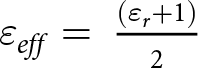 ${\varepsilon _{eff}} = {\text{ }}\frac{{\left( {{\varepsilon _r} + 1} \right)}}{2}$), and ε r is the relative permittivity of the substrate. Here, a i signifies the length from the vertex of the inner edge of the semi-elliptical slot, and b i signifies the base width of the respective ith port, as shown in Figure 2(c) and 2(d). ∆a max_i is the maximum perpendicular distance between the arc of the semi-elliptical slot facing the port and the hypotenuse of the triangle, which has a height of a i and a base width of b i/2, as shown in Figure 2(d). The value of a i and b i should be at least λ g/2 and λ g/4, respectively, where λ g (= λ 0/
 $\sqrt {{\varepsilon _{\text{r}}}} $) is the guided wavelength at the operating frequency. Specifically in OEMSIW, the length is halved along the a i dimension, and the width is quartered along the b i dimension compared to a full-mode waveguide, resulting in half-wavelength and quarter-wavelength resonances along the respective dimensions. Due to the loading effect, the resonant frequency of the radiator is slightly deviated from the frequency obtained from (1). Hence, this equation is only used as an initial design guideline.
E-field distribution
The power supplied to an individual port can be coupled with the other radiators, which leads to poor isolation. Therefore, vias are introduced on the diagonals of the octagon according to the design rule (2) to reduce the power coupling among the radiators and increase the isolation between ports [Reference Xu and Wu25]
 \begin{equation}p \lt 2.5{\text{ }}d\end{equation}
where p is the pitch, the longitudinal spacing between centers of two adjacent vias, and d is the diameter of the via. The minimum simulated isolation between any two ports, without vias on the diagonals, was −19.8 dB. When vias were placed along the full length of the four diagonals, minimum simulated isolation improved significantly to −30 dB. Therefore, the number of vias along the diagonals was optimized to maintain high isolation between the ports without significantly increasing fabrication complexity. The vias act as an electrical wall and confine the electric field in the intended cavity. A semi-elliptical-shaped perfect electric and perfect magnetic conductor wall is placed adjacent to the etched radiator for port number 8 without altering the dimensions of the cavity. The cavity dimensions are kept intact. For analyzing the surface EM energy distribution, a perfect electric conductor wall (PECW) and a perfect magnetic conductor wall (PMCW) are introduced just above the slot of port 8. Figure 3(a) illustrates the vector electric field distribution for the cases with PECW and PMCW. It is observed that the z-directed electric field corresponding to the TE10 mode of the eighth-mode cavity excites the odd mode of the slotline. Nearly 100% radiation efficiency is achieved with a radiating slot width of 1.4 mm. However, a further increase in the slot width degrades the cross-polarization performance [Reference Priya, Dwari, Kumar and Mandal12]. Figure 3(b) presents the reflection coefficient responses for three cases: without any wall, with PECW, and with PMCW. The reflection characteristics show close agreement in all three cases, indicating negligible EM energy leakage to other ports through the cavity surface. This confirms that almost all the input energy is radiated through the slots. Consequently, very high isolation (greater than 30 dB) is maintained among the radiation cavities. The electric field distribution when a single port is excited individually is shown in Figure 4(a)–4(h). Each divided cavity supports the perturbed one-eighth of TE110 mode, as evident by the electric field distribution. The signal propagates from an excited port and radiates upon encountering a discontinuity in the form of the corresponding designed semi-elliptical slot. The resonant frequency of the radiated field depends on the dimension of the open edge of the slot. This radiation is primarily due to the fringing electric fields at the edges of the slot, as shown by the vector electric field distribution of the proposed antenna for each port in Figure 5(a)–5(h).
(a) Vector electric field distribution at 4.72 GHz for port 8 with a perfect electric and a perfect magnetic wall placed inside the OEMSIW cavity. (b) Reflection coefficient comparison when port 8 is excited.

Electric-field distributions when (a) port 1, (b) port 2, (c) port 3, (d) port 4, (e) port 5, (f) port 6, (g) port 7, and (h) port 8 are excited individually.

Vector electric-field distributions when (a) port 1, (b) port 2, (c) port 3, (d) port 4, (e) port 5, (f) port 6, (g) port 7, and (h) port 8 are excited individually.

Equivalent circuit model
The equivalent circuit model serves as a benchmark for simulating the antenna’s complex EM behavior in terms of lumped electrical circuit components like resistors, inductors, and capacitors. A circuit model simplifies the analysis and enables smoother integration in complex systems where antennas are part of larger electronic systems. Therefore, a schematic diagram of the equivalent circuit model of the proposed self-octuplexing antenna is presented in Figure 6. The circuit model is designed, simulated, and validated using Keysight Advanced Design System software. The values of the lumped elements and the turn ratio are iteratively optimized till there is a significant agreement in the S parameter values of the circuit and EM model of the proposed antenna. The optimized value of the lumped circuit components is given in Table 1. Here, R Ei is resistance, C Ei is capacitance, and L Ei is inductance associated with the individual cavity of the ports, and i signifies the port number varying from 1 to 8. A parallel resistor (R), inductor (L), and capacitor (C) (RLC) circuit can represent each one-eighth cavity resonator. The eight radiating elements, etched in the form of semi-elliptical ring-shaped slots etched on the octagonal resonator, act as shunt capacitors and are represented by C Si. A series LC circuit is used as an equivalent circuit to model mutual coupling (M ij) between any two ports, numbered i and j, where i ≠ j. C Mij represents mutual capacitance, and L Mij represents mutual inductance between the ports. The transformers Ni (i = 1–8) represent the impedance matching between the ports and the RLC circuit networks. The resonant frequency and the input impedance of the resonators are determined by (3) and (4) [Reference Marcuvitz26].
 \begin{equation}{f_{0i}} = {\text{ }}\frac{1}{{2\pi \sqrt {{L_{Ei}}{C_{Si}}} }}\end{equation}
Equivalent circuit of the proposed self-octuplexing antenna.

Value of components of the circuit model

Notes: Comp. stands for Component; Units: Resistance = Ω, inductance = nH, and capacitance = pF.
The input impedance is given by
 \begin{equation}{Z_{in}} = {\text{ }}\frac{{j{\omega _{0i}}{L_{Ei}}}}{{1 - {\text{ }}\omega _{0i}^2{L_{Ei}}{C_{Si}}}}\end{equation}
The resonant frequency is inversely proportional to the shunt capacitance C Si as given in Equation (3), and the slot dimension is directly proportional to the shunt capacitance. Therefore, when the slot dimension is increased, the associated capacitance increases, decreasing the resonant frequency. The antenna’s resonant frequency can be varied by changing the slot dimension. Hence, the miniaturization of the antenna can be achieved by reducing the slot dimensions. The comparison between the reflection coefficient obtained from EM simulation and circuit simulation is given in Figure 7. There is a notable agreement between the reflection coefficient values obtained from EM simulations and those derived from circuit simulations. The isolation values between any two ports exceed 30 dB in both simulations, as shown in Figure 8, which depicts the comparison between circuit simulation’s and EM simulation’s isolation values.
Reflection coefficient for EM and circuit simulation of the proposed antenna.

Isolation for (a)–(d) EM simulation and (e)–(h) circuit simulation of the proposed antenna.

Tuning of operating frequencies
The proposed antenna design allows easy tuning of each resonant frequency independently using a single variable G sloti, where G sloti is the distance of the respective ith slot from the vias at the periphery. Figure 1 shows a representative G sloti for a single slot. A parallel resonant circuit represents an unperturbed one-eighth-mode cavity. A shunt capacitance in the equivalent parallel RLC circuit model represents the radiating slot. Therefore, when the slot is moved radially inwards, the capacitance increases. As the resonant frequency is inversely proportional to capacitance, hence the resonant frequency decreases. Figure 9 shows the variation in reflection coefficient at the resonant frequency due to changes in the radial position of the slot for G slot1 = 1.54, 1.74, 1.94, 2.14, and 2.34 mm, with the highest resonant frequency obtained at G slot1 = 1.54 mm and the lowest resonant frequency obtained at G slot1 = 2.34 mm. There is no significant effect on other antenna performance characteristics as frequency tuning is performed without altering the initial cavity dimensions. The proposed antenna can be operated at any desired frequency between 2.47 and 4.96 GHz by varying the distance of the respective ith slot from the vias at the periphery (G sloti). In all the cases, simulated isolation is maintained better than 30 dB.
Variation in reflection coefficient with G slot1 keeping other dimensions constant (a) port 1, (b) magnified view of frequency variation.

In addition to slot positioning, the effect of cavity radius, R TOP, on the antenna performance is examined. When cavity radius R TOP is increased while keeping the slots at the same absolute position as in the original design, a decrease in the resonant frequency and poor impedance matching are observed. This behavior is consistent with the explanation discussed above. In this case, increasing the cavity dimension effectively moves the slots radially inward with respect to the new cavity boundary, which increases the dimension a i from the outer wall of cavity, thus lowering the resonant frequency observed as Equation (1).
In contrast, when R TOP is increased while maintaining the relative distance of each slot from the respective port, that is, preserving the values of G sloti as in the original design, the resonant frequency of the ports remains unchanged since the a i remains constant, as shown in Figure 10. However, an improvement of 0.46 dB in minimum isolation is observed due to the increased physical separation between the radiating slots, which occurs with an increase in R TOP. Figure 11(a)–11(f) shows isolation values when R TOP is 47.14 and 51.06 mm. Therefore, the value of R TOP kept optimum to maintain isolation among the elements is better than 30 dB in a smaller antenna size.
Reflection coefficient for different values of R TOP.

Isolation for different values of R TOP.

The following design steps are suggested based on the above study:
1) Select an octagonal cavity with a dimension of its circumradius
 $ \approx $ 0.58 λ g, where λ g = λ0/
$\sqrt {{\varepsilon _{\text{r}}}} $ at the lowest mid-band frequency.
2) Place the slots with length λ g/2, at λ g/4 from the respective port, where λ g corresponds to their respective guided wavelengths.
3) Optimize for |S 11| < −15 dB for each port by varying the length of the respective inset.
4) Adjust the slot length or slot position to get the desired resonant frequency.
5) Repeat steps (3) and (4) for each slot till the intended results are obtained.


Result and discussion
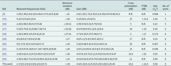
The self-octuplexing SIW cavity-backed slot antenna is fabricated on Rogers RT/Duroid 5880 substrate to validate the design. Figure 12(a) shows the top view, and Figure 12(b) shows the ground plane view of the fabricated antenna. The diagram of the measurement setup inside the anechoic chamber is given in Figure 12(c). A broadband horn antenna is used as a transmitting antenna, while the fabricated antenna is placed in a receiving configuration at the receiver side. While measuring the parameters of the fabricated antenna, the excitation is applied sequentially to one port at a time while the remaining unused ports are terminated with 50 Ω matched loads. The excitation signal and the measurement procedure are carried out using a Keysight PNA Network Analyzer N5225B. Figure 12(d) shows the actual measurement setup. There is a significant agreement between the proposed antenna’s simulated and measured reflection coefficients, as shown in Figure 13(a). The measured gains and antenna efficiencies are depicted in Figure 13(b). The measured efficiency and gain are better than 70% and 4.03 dBi, respectively. A slight deviation in measured efficiency occurs due to an increase in directivity caused by a decrease in half-power beamwidth, as seen in Figure 15. As the octagon is divided into equal triangles, the radiating elements at higher frequencies have relatively larger apertures than those radiating at lower operating frequencies. This leads to an increase in the gain of each antenna port as the resonant frequency increases. The measured efficiency is better than 70%. Figure 14(a)–14(f) presents the measured and simulated isolation values. The measured isolation is better than 34 dB among all the ports. Figure 15 depicts the radiation patterns for each port at their respective operating frequency. The antenna has a measured cross-polarization level below −24.2 dB in the boresight direction in all bands. The FTBR is more than 10.4 dB in all bands. The measured antenna parameters for each port at the respective frequency are listed in Table 2. A comparison of various performance parameters of the proposed work with previous work is summarized in Table 3. This antenna provides a low co-to-cross polarization level and high isolation among [Reference Hussain3, Reference Chaturvedi, Kumar, Althuwayb and Ahmadfard15–Reference Srivastava, Mohan, Kanaujia and Matekovits23] with similar values of gain.
Fabricated antenna structure (a) top view, (b) ground plane view, (c) diagram of measurement setup, and (d) measurement setup in anechoic chamber.

Simulated and measured (a) reflection coefficient and (b) gain and efficiency.

Simulated and measured isolation for the proposed antenna.

Simulated and measured radiation pattern at (a) 2.7 GHz, (b) 3.0 GHz, (c) 3.3 GHz, (d) 3.6 GHz, (e) 3.9 GHz, (f) 4.2 GHz, (g) 4.5 GHz, and (h) 4.72 GHz.

Measured antenna parameters

Comparison of the proposed self-octuplexing antenna with previous SIW antenna designs

Note: N.R.: not reported.
Conclusion
This paper proposes a self-octuplexing SIW cavity-backed slot antenna for octa-band wireless communication services. All bands can be independently tuned to operate at the desired frequency according to the required functionality. The antenna achieves a low co-to-cross polarization level and high isolation with moderate gains. This work offers designers flexibility in accommodating multiple functionalities in a single device compared to previous SMA designs. This antenna is useful for 5 G communication, wireless local area network, standard C-band, super-extended C-band, LMI-C-band, radio navigation services, amateur radio, satellite communication, and other multifunction applications.
Acknowledgements
We would like to thank the Science and Engineering Research Board (SERB), DST, Govt. of India, for providing basic infrastructure for this work under the sanctioned project number SRG/2022/000664. We would also like to thank Dr. B. R. Ambedkar NIT Jalandhar, for providing fabrication facility under the sanctioned project number NITJ/DRC/4710.
Competing interests
The authors report no competing interests.

Swapnil Shekhar received his B.E. degree in Electronics and Communication Engineering from Thapar Institute of Engineering and Technology, Patiala, India, in 2019 and received his M.Tech. degree from Sant Longowal Institute of Engineering and Technology, Sangrur, India, in 2023. He is currently pursuing his Ph.D. degree from the Department of Electrical Engineering, Indian Institute of Technology, Delhi, India. His research interests include the development of novel antennas, SIW, smart sensors, and their integration.

Kundan Kumar received his B.Tech. in Electronics and Communication Engineering in 2012, M.Tech. and Ph.D. in Electronics and Communication Engineering from the Indian Institute of Technology (ISM), Dhanbad, Jharkhand, India, in the year 2015 and 2020, respectively. Dr. Kumar is working as an Assistant Professor in the Department of Electronics and Communication Engineering at Dr. B R Ambedkar National Institute of Technology Jalandhar, Punjab, India. Prior to this, he worked as an Assistant Professor in the Department of Electronics and Communication Engineering at PEC Chandigarh and SLIET Longowal, respectively. Dr. Kumar was continuously qualified seven times for the Graduate Aptitude Test in Engineering in the subject of Electronics and Communication Engineering and was in the top 0.76% of students in 2013. He was also continuously qualified twice for the National Eligibility Test for Assistant Professor in Electronic Science under the University Grants Commission in June 2014 and December 2014. Dr. Kumar received the Research Publication Award by IIT Dhanbad in the year of 2017 and the Research Project Award by SLIET Longowal in the year of 2023. Dr. Kumar has published 25 research papers in refereed International Journals (like IEEE Transactions on Antennas and Propagation, IEEE Antennas and Wireless Propagation Letters, etc.) and Conferences. Dr. Kumar delivered expert talks in several institutes. He is a regular reviewer of various refereed International Journals like IEEE Transactions on Antennas and Propagation, IEEE Antennas and Wireless Propagation Letters, etc. His research interests include 5G antennas and circuits, RF and millimeter wave antennas, intelligent antennas for cognitive radio, characterization of dielectric material, modeling and analysis of SIW-based antennas, SMAs, RF planar circuits, RF/microwave sensors, and computational EMs.

Shruti Priya received her B.Tech. in Electronics and Communication Engineering in 2012 from Dr. M. G. R. Educational and Research Institute, Chennai, India, M.Tech. in Digital Communication in 2015 from RGPV, Bhopal, India and PhD from Indian Institute of Technology (ISM) Dhanbad, India. She worked as a post-doctoral fellow and Research Associate at the Institute for Plasma Research, Gandhinagar, India, and the Indian Institute of Technology Mandi, India, respectively. Shruti Priya has published several research papers in refereed International Journals and Conferences. Her research interests are in SIW-based antennas, multiband antennas, and SMAs.

Nitesh Kashyap is an Assistant Professor in the Department of Electronics and Communication Engineering at Dr. B.R. Ambedkar National Institute of Technology, Jalandhar. He holds a B.Tech. and M.Tech. in Electronics and Communication Engineering, and earned his Ph.D. with a specialization in planar antennas. With over 10 years of experience in teaching and research, he has published more than 31 research papers in reputed journals and conferences, along with several book chapters. He has supervised one Ph.D. scholar and is currently guiding four more. Additionally, he has mentored 11 M.Tech. dissertations across various domains of communication and microwave engineering.

Surinder Singh was born in Hoshiarpur, Punjab, India, in 1975. He received the B.Tech. degree from Dr. B. R. Ambedkar REC, Jalandhar, India, in 1997, and the M.Tech. degree from the Guru Nanak Dev Engineering College, Ludhiana, India, in 2003, and the Ph.D. degree from Thapar University, Patiala, India, in 2007. Currently, he has been a Professor at Sant Longowal Institute of Engineering and Technology, Longowal, Sangrur, Punjab, since 2013. He has around 230 research papers, out of which 126 are in SCI international journals with Thomson Reuters Impact Factor and 104 are in international and national conferences. He is also handling various research projects and is a reviewer of many international journals and conferences. His field of interest includes optical fiber communication and networks, antennas, and optical sensor design.