I. INTRODUCTION
The effects of solute elements on the fracture energy and the generalized stacking fault energy (GSFE) are interesting studies not only for technological applications but also from a scientific view because the nature of ductility in condensed matters depends on the fracture energy and the GSFE.Reference Rice1 When a lattice strain is generated, e.g., by a difference in the atomic size between a solute atom and a solvent atom, the fracture energy may reduce. On the other hand, when intense atomic interactions such as covalent bonding occur between a solute atom and a solvent atom, the fracture energy will increase. Hence, effects of solute elements can be divided into the mechanical effect due to a difference in atomic size and the chemical effect related to atomic bonding characteristics. To date, there are many studies using the first-principles calculations to investigate the mechanical and chemical effects on the fracture energy (or work of separation) of grain boundaries.Reference Wu, Freeman and Olson2–Reference Tian, Yan, Hao and Xiao13 Shang and WangReference Shang and Wang4 investigated effects of solute Nb and V on grain boundary fracture of Fe and suggested that the mechanical effect enhanced the grain boundary embrittlement, but the chemical effect suppressed it. Lozovoi et al.Reference Lozovoi, Paxton and Finnis8 reported that enhanced embrittlement of a Cu grain boundary segregated by Bi and Na was primarily related to the mechanical effect. Razumovskiy et al.Reference Razumovskiy, Ruban, Razumovskii, Lozovoi, Butrim and Vekilov12 showed that Mg and Zr solute atoms strengthened an Al grain boundary due to the chemical effect. These works suggested that the mechanical effect decreased the fracture energy, while the chemical effect increased the fracture energy. However, Zhong et al.Reference Zhong, Wu, Freeman and Olson14 showed that in a Fe–H system, the mechanical effect increased the fracture energy, and the chemical effect decreased it. The decreased fracture energy due to the chemical effect is because of the charge transfer from Fe to H atoms.Reference Zhong, Wu, Freeman and Olson14,Reference Yuasa, Amemiya and Mabuchi15 Thus, there are many understandings of the mechanical and chemical effects on the fracture energy.
The GSFE also depends on the expansion (or contraction) and chemical states of the interatomic bonds. To date, the GSFEs have been investigated for many metallic materials.Reference Mryasov, Gronostyrev and Freeman16–Reference Muzyk, Pakiela and Kurzydlowski23 SiegelReference Siegel19 investigated the effects of the solute elements on the GSFE of Ni by the first-principles shear tests and showed that the GSFE increased with the addition of Mn and Fe, while it decreased with the addition of Cu, Nb, and W. Thus, the effects of the solute elements on the GSFE are complicated, and systematic investigations are needed to understand these effects. To the authors' knowledge, there are no studies about the mechanical and chemical effects on the GSFE. Investigations of the GSFE from the viewpoint of the mechanical and chemical effects can give an insight into understanding the effects of the solute elements on the GSFE.
Magnesium alloys are promising light structural materials due to their high specific strength and stiffness. However, Mg alloys often show low ductility and poor stretch formability because the slip systems are limited. Recently, it was found that the formability of Mg was significantly improved by the addition of a small amount of solute elements such as Ca.Reference Chino, Sassa and Mabuchi24–Reference Chino, Ueda, Otomatsu, Sassa, Huang, Suzuki and Mabuchi27 This suggests that the GSFE of Mg is strongly affected by solute elements. There are some studies on the GSFEs of pure Mg and Mg alloys.Reference Uesugi, Kohyama, Kohzu and Higashi28–Reference Zhang, Fan, Fu, Tang, Peng and Ding35 However, understanding about the effects of the solute elements on the GSFE of Mg is still insufficient. In the present study, first-principles shear tests were performed on seven Mg models (pure Mg, Mg–Li, Mg–Ca, Mg–Al, Mg–Sn, Mg–Ag, and Mg–Zn models), and the mechanical and chemical effects of the solute elements on the GSFE of Mg were investigated.
II. CALCULATION METHOD
First-principles calculations were performed using the Cambridge Serial Total Energy Package (CASTEP),Reference Clark, Segall, Pickard, Hasnip, Probert, Refson and Payne36 in which the density functional theory (DFT)Reference Hohenberg and Kohn37,Reference Kohn and Sham38 was used with a plane-wave basis set. The Perdew-Wang (PW91) version of the generalized gradient approximation was used to represent exchange-correlation functional in the DFT. Ultrasoft pseudopotentialsReference Vanderbilt39 were used for all the elements in the calculations. The plane-wave energy cutoff was 380 eV. The Brillouin zone was sampled using the 4 × 4 × 1 Monkhorst-Pack k-point gridReference Monkhhost and Pack40 for all the models, and the Gaussian smearing was set with a width of 0.1 eV.
A schematic illustration of a supercell used for the calculation is shown in Fig. 1. A cell for the pure Mg model consisted of 12 layers in the [0001] direction and the unit cell contained 48 Mg atoms. The size of the unit cell was 5.6 × 6.4 × 43.7 Å3. A vacuum slab with a width of 15 Å was added to avoid interactions with the periodic image and to relax the cell in the [0001] direction. A cell for Mg alloy models was prepared by substituting one Mg atom (a red sphere in Fig. 1), which was adjacent to the slip plane, by one solute atom. The solute atoms investigated were Li, Ca, Al, Sn, Ag, and Zn. M1 ∼ M6 Mg atoms were defined as shown in Fig. 1. These atoms were the nearest neighbor atoms to a solute atom. All atomic positions were optimized in accordance with the Hellman-Feynman forces of less than 0.01 eV Å−1. These conditions provided good convergence. All calculations of the local density of states (LDOS) were performed after the geometry optimization.
A schematic illustration of a supercell model for first-principles shear tests: (a) a front view and (b) a top view of L07 layer. The atoms marked M1–M6 are the nearest neighbor Mg atoms to a solute atom. In (a), the dashed line indicates the (0001) slip plane. The upper six layers L07–L12 are sheared according to the slip system  $\left[ {10\bar 10} \right]$ (0001). In (b), the red sphere indicates a solute atom (Li, Ca, Al, Sn, Ag, or Zn), and circles and triangles indicate atoms in the L06 and L07, respectively.

The first-principles shear test was calculated by cutting a perfect crystal with two free surfaces and displacing the two parts relative to each other on the fault vector, x, in a slip plane.Reference Vitek41,Reference Vitek42 The GSFE was defined as a difference in total energies between the two supercells designed to simulate faults with the x = 0 and x ≠ 0 vectors for the basal plane:  $[10\bar 10]$ (0001) slip system. The atomic positions were relaxed only in the direction perpendicular to the slip plane. The maximum of GSFE along the
 $[10\bar 10]$ direction was defined as the unstable stacking fault energy (USFE).
The strained model was used to assess the mechanical and chemical effects based on the studies of grain boundary segregation.Reference Wu, Freeman and Olson2,Reference Geng, Freeman, Wu, Geller and Raynolds3,Reference Braithwaite and Rez7–Reference Lozovoi and Paxton9 The strained model was the cell model where a solute atom in a Mg alloy model was replaced by a Mg atom, keeping the same atomic configuration in the Mg alloy model without further relaxation. The GSFE related to the mechanical and chemical effects can be given by
 $${E_{{\rm{mech}}}} = {E_{{\rm{strained}}}} - {E_{{\rm{pure}}}}\quad {\rm{,}}$$
and
 $${E_{{\rm{chem}}}} = {E_{{\rm{alloy}}}} - {E_{{\rm{strained}}}}\quad {\rm{,}}$$
where E mech and E chem are the GSFEs related to the mechanical effect and to the chemical effect, and E pure, E alloy, and E strained are the GSFEs of the pure Mg model, the Mg alloy model, and the strained model, respectively. The values of E mech and E chem at the strain where the USFE was obtained are denoted as E mech,u and E chem,u. In the present work, the relationship between the USFE and the cohesive energy was investigated from the viewpoint of the mechanical and chemical effects. The cohesive energy can be given by
 $${E_{{\rm{coh}}}} = {{{E_{{\rm{supercell}}}} - \left( {{E_{{\rm{Mg}}}} \times 47 + {E_{{\rm{solute}}}}} \right)} \over {48}}\quad {\rm{,}}$$
where E coh is the cohesive energy, E supercell is the total energy of a supercell, and E Mg and E solute are the energies of an isolated Mg atom and an isolated solute atom, respectively. In the present work, the cohesive energy related to the mechanical and chemical effects were calculated on the pattern of the USFE. Namely, the cohesive energy related to the mechanical and chemical effects may be given by
 $${E_{{\rm{mech,c}}}} = {E_{{\rm{strained,c}}}} - {E_{{\rm{pure,c}}}}\quad ,$$
and
 $${E_{{\rm{chem,c}}}} = {E_{{\rm{alloy,c}}}} - {E_{{\rm{strained,c}}}}\quad {\rm{,}}$$
where E mech,c and E chem,c are the cohesive energies related to the mechanical effect and the chemical effect, and E pure,c, E alloy,c, and E strained,c are the cohesive energies of the pure Mg model, the Mg alloy model, and the strained model, respectively.
III. RESULTS AND DISCUSSION
A. GSFE
Figure 2(a) shows the GSFE curves for the pure Mg and Mg alloy models. The USFE was 94 mJ/m2 for pure Mg, 96 mJ/m2 for Mg–Li, 85 mJ/m2 for Mg–Ca, 71 mJ/m2 for Mg–Al, 55 mJ/m2 for Mg–Sn, 100 mJ/m2 for Mg–Ag, and 84 mJ/m2 for Mg–Zn. Consequently, the order of USFE was Mg–Ag > Mg–Li > pure Mg > Mg–Ca > Mg–Zn > Mg–Al > Mg–Sn. The trends obtained in the present work correspond to the ones in the previous study.Reference Muzyk, Pakiela and Kurzydlowski34 It is known that the  $\left[ {10\bar 10} \right]$ (0001) slip system for hcp metals depends on the axial c/a ratio, where c is the c-axial lattice parameter and a is the a-axial lattice parameter. The lattice parameter of the a-axis was obtained by averaging the lengths of solute–M4, –M5, and –M6 bonds in Fig. 1, and the lattice parameter of the c-axis was calculated by the length between the layers L05 and L07. The value of the c/a ratio was 1.625 for pure Mg, 1.617 for Mg–Li, 1.660 for Mg–Ca, 1.592 for Mg–Al, 1.623 for Mg–Sn, 1.574 for Mg–Ag, and 1.571 for Mg–Zn, and the order of the c/a ratio was Mg–Ca > pure Mg > Mg–Sn > Mg–Li > Mg–Al > Mg–Ag > Mg–Zn. According to the order of the c/a ratio, Mg–Ca is expected to show the largest USFE. However, the USFE of Mg–Ca was lower than that of Mg–Ag, Mg–Li, and pure Mg models. Thus, the trend of USFE is not necessarily explained by the c/a ratio.
Generalized stacking fault energy (GSFE) curves for the slip system  $\left[ {10\bar 10} \right]$ (0001): (a) pure Mg and Mg alloy models and (b) strained models, where x is the displacement and b is the Burgers vector (= 1/3
 $\left[ {10\bar 10} \right]$) of a partial dislocation for basal slip in Mg.
The relationship between the USFE and the cohesive energy, E coh, is shown in Fig. 3. It can be seen that there is little relation between the USFE and the cohesive energy. In the calculation of the cohesive energy, the breaking of all atomic bonds is measured. In the calculation of the GSFE, however, the breaking of only atomic bonds across the slip plane is measured. Because covalent-like and ionic-like characteristics often have an intense anisotropic nature, a trend of the whole of a solid solution does not necessarily correspond to that of its part when atomic bonds between a solvent atom and a solute atom have covalent-like and/or ionic-like characteristics. This may account for the little relation between the USFE and the cohesive energy.
The relationship between the USFE and the cohesive energy, E coh.
B. Mechanical effect
Figure 2(b) shows the GSFE curves for the strained models. The mechanical and chemical effects on the GSFE were estimated by the results of Figs. 2(a) and 2(b). Figure 4(a) shows the GSFE curves related to the mechanical effect (E mech). It is noted that the mechanical effect induced an increased USFE, independent of the kind of solute element. This suggests that the strain generated by a difference in atomic size hampers the dislocation glide, which results in solid solution hardening.
GSFE curves related to (a) mechanical effect, E mech, and (b) chemical effect, E chem, where x is the displacement and b is the Burgers vector (= 1/3  $\left[ {10\bar 10} \right]$) of a partial dislocation for basal slip in Mg. The GSFEs related to the mechanical effect, E mech, and the chemical effect, E chem, are given by E mech = E strained − E pure and E chem = E alloy − E strained, where E pure, E alloy, and E strained are the GSFEs of pure Mg model, Mg alloy model, and strained model, respectively.
The relationship between the mechanical effect on the USFE, E mech,u, and the mechanical effect on the cohesive energy, E mech,c, is shown in Fig. 5. The E mech,c increased with increasing E mech,u, although the Mg–Ca model deviated from the relationship of the other models. This indicates that the instability in a Mg solid is increased by the mechanical effect.
The relationship between the mechanical effect on the USFE, E mech,u, and the mechanical effect on the cohesive energy, E mech,c. E mech,u is the GSFE related to the mechanical effect at the strain where the USFE was obtained, and E mech,c is the cohesive energy related to the mechanical effect.
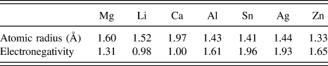
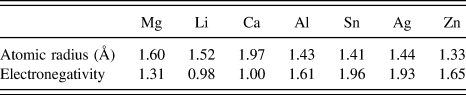
It is accepted that solution hardening is an increasing function of the misfit strain. For the sake of an easy estimation of hardening, a difference in the atomic radius between a solute atom and a solvent atom in a single solid of each element is often used as the misfit strain. The radius of an atom in a single solid of each element investigated in this work is listed in Table I. It can be seen from Table I that the order of difference in the atomic radius between a Mg atom and a solute atom is Ca > Zn > Sn > Al > Ag > Li. However, the order of E mech,u was Ag > Zn > Ca > Al > Li > Sn [Fig. 4(a)]. Hence, the mechanical effect cannot be explained by the misfit strain simply calculated with the atomic radii in single solids. Figure 6 shows the relationship between the mechanical effect, E mech,u, and the average atomic distance between a solute atom and surrounding Mg atoms in the initial Mg alloy models, which indicates the atomic strain. The average atomic distance was calculated by averaging the atomic distances from a solute atom to the M1 ∼ M6 Mg atoms after the initial geometry optimization. The mechanical effect increased with a difference in the average atomic distance between the pure Mg model and the Mg alloy model. It is interesting to note that a difference in the average atomic distance did not correspond to the simply-calculated misfit strain. For example, the simply-calculated misfit strain of the Mg–Ag model is the fourth largest among the Mg alloy models, but the difference in the average atomic distance between the Mg–Ag model and the pure Mg model is the largest. As shown later, the Mg–Ag bond has covalent-like characteristics. Hence, the atomic distance of Mg–Ag becomes less than expected from their atomic sizes in single solids.
The atomic radius and electronegativity of elements investigated in the present work.44,Reference Allred45
The relationship between the mechanical effect on the USFE, E mech,u, and the average atomic distance. The average atomic distance was calculated by averaging the distances from the solute atom to the surrounding Mg atoms (M1 ∼ M6).
Another interesting result in Fig. 6 is that the mechanical effect tended to be more intense for substitution of a smaller atom, compared with substitution of a larger atom. IIkubo et al.Reference Iikubo, Matsuda and Ohtani43 investigated the volume dependence of the GSFE in Mg and they showed that the GSFE increased with decreasing volume. The atomic distances of Mg–Mg bonds around a substituting atom are shortened by the substitution of a smaller atom, while they are enlarged by the substitution of a larger atom. The shortened Mg–Mg bonds require a larger stress for shearing, compared with the enlarged Mg–Mg bonds. This may contribute to the more intense mechanical effect of a smaller atom.
It is worthwhile to investigate the electronic states before and after the deformation. The LDOS of the M1 Mg atom at x/b = 0 and 0.6 for the Mg–Sn and Mg–Ag models are shown in Fig. 7, where x is the displacement and b is the Burgers vector. The LDOS at x/b = 0.6 differed a little from that at x/b = 0 for the strained models. Hence, the electronic states for the strained models were not changed drastically by deformation.
LDOS of M1 Mg atom at x/b = 0 and 0.6 for the strained models: (a) Mg–Ag model and (b) Mg–Sn model, where x is the displacement and b is the Burgers vector (= 1/3  $\left[ {10\bar 10} \right]$) of a partial dislocation for basal slip in Mg. The Fermi level defines the zero energy.
C. Chemical effect
Figure 4(b) shows the GSFE curves related to the chemical effect, E chem. The GSFE tended to be reduced by the chemical effect for all the Mg alloy models except the Mg–Li model. It is noted that the USFE was increased by the chemical effect only in the case of the Mg–Li model, while the USFE was reduced by the chemical effect in all the other alloy models. A reduction in the USFE by the chemical effect was larger for the Mg–Al, Mg–Zn, and Mg–Sn models than for the Mg–Ca and Mg–Ag models. In particular, the effect was significantly larger for the Mg–Al and Mg–Sn models.
The relationship between the chemical effect on the USFE, E chem,u, and the chemical effect on the cohesive energy, E chem,c, is shown in Fig. 8. The values of E chem,c were negative in all the Mg alloy models, independent of the positive and negative values of E chem,u. This suggests that the chemical effect makes a Mg solid stable, in contrast to the mechanical effect.
The relationship between the chemical effect on the USFE, E chem,u, and the chemical effect on the cohesive energy, E chem,c. E chem,u is the GSFE related to the chemical effect at the strain where the USFE was obtained, and E chem,u is the cohesive energy related to the chemical effect.
It can be seen from Fig. 4(b) that the order of the reduction in E chem,u was Sn > Al > Zn > Ca > Ag (> Li). The order of electronegativity is Sn > Ag > Zn > Al > Mg > Ca ≅ Li (Table I).44,Reference Allred45 It appears that a solute element with larger electronegativity gives rise to a larger reduction in USFE due to the chemical effect, except for Ag and Zn. A solute atom with large electronegativity takes electrons away from the Mg atoms around the solute atom, and this charge transfer weakens the bonding between the Mg atoms.Reference Zhong, Wu, Freeman and Olson14,Reference Zamora, Nair, Hennig and Warne46 This is probably responsible for the large reduction in E chem,u by the addition of a solute element with large electronegativity.
The chemical effects of Ag and Zn were low, however, despite their large electronegativity. In particular, the electronegativity of Ag was the second largest in all the solute elements investigated, but the reduction in USFE due to the chemical effect by Ag was rather low. It appears that the chemical effect is more complicated compared with the mechanical effect. To investigate the chemical effect in more detail, the LDOS of the M1, M4 Mg atoms and the solute atom are shown in Figs. 9–15. The M1 Mg atom is located at the upper layer on the slip plane and the M4 Mg atom and the solute atom are located at the lower layer. Hybridization-like peaks between the solute atom and the surrounding Mg atoms were not found in the Mg–Li and Mg–Ca models. The trend of no covalent-like characteristics was found during deformation [Fig. 16(b)]. On the other hand, hybridization-like peaks were observed in the Mg–Al, Mg–Sn, Mg–Ag, and Mg–Zn models. Inspection of Figs. 12 and 15 reveals that the hybridization-like peaks were not found for the M1 Mg atom, but the M4 Mg atom in the Mg–Al and Mg–Zn models. This suggests that the covalent-like characteristics in the Mg–Al and Mg–Zn models hardly affect the chemical effect. Also, as shown in Fig. 13, hybridization-like peaks were very low in the Mg–Sn model, indicating that the chemical effect due to the covalent-like characteristics was minor in the Mg–Sn model. In the Mg–Ag model, however, large hybridization-like peaks, which were related to the interaction between the s- and p-orbitals of Mg and the d-orbitals of Ag, were observed around −5 eV for both the M1 and M4 atoms. The covalent-like bonding was found during the deformation in the Mg–Ag model [Fig. 16(c)]. The isotopic covalent-like characteristics strengthen the Mg–Ag bonds across the slip plane. Therefore, it is suggested that the low chemical effect of Ag is a result of the offset of the covalent-like characteristics and the ionic-like characteristics.
LDOS of a Mg atom in the pure Mg model. The Fermi level defines the zero energy.
LDOS in the Mg–Li model: (a) M1 Mg atom, (b) M4 Mg atom, and (c) Li atom. The M1 Mg atom is located at the upper layer on the slip plane, and the M4 Mg atom and the Li atom are located on the lower layer. The Fermi level defines the zero energy.
LDOS in the Mg–Ca model: (a) M1 Mg atom, (b) M4 Mg atom, and (c) Ca atom. The M1 Mg atom is located at the upper layer on the slip plane, and the M4 Mg atom and the Ca atom are located on the lower layer. The Fermi level defines the zero energy.
LDOS in the Mg–Al model: (a) M1 Mg atom, (b) M4 Mg atom, and (c) Al atom. The M1 Mg atom is located at the upper layer on the slip plane, and the M4 Mg atom and the Al atom are located on the lower layer. The Fermi level defines the zero energy.
LDOS in the Mg–Sn model: (a) M1 Mg atom, (b) M4 Mg atom, and (c) Sn atom. The M1 Mg atom is located at the upper layer on the slip plane, and the M4 Mg atom and the Sn atom are located on the lower layer. The Fermi level defines the zero energy.
LDOS in the Mg–Ag model: (a) M1 Mg atom, (b) M4 Mg atom, and (c) Ag atom. The M1 Mg atom is located at the upper layer on the slip plane, and the M4 Mg atom and the Ag atom are located on the lower layer. The Fermi level defines the zero energy.
LDOS in the Mg–Zn model: (a) M1 Mg atom, (b) M4 Mg atom, and (c) Zn atom. The M1 Mg atom is located at the upper layer on the slip plane, and the M4 Mg atom and the Zn atom are located on the lower layer. The Fermi level defines the zero energy.
LDOS of M1 Mg atom at x/b = 0 and 0.6 (0.5): (a) pure Mg model, (b) Mg–Li model, and (c) Mg–Ag model, where x is the displacement and b is the Burgers vector (= 1/3  $\left[ {10\bar 10} \right]$) of a partial dislocation for basal slip in Mg. LDOS at x/b = 0 and 0.6 are shown for the pure Mg and Mg–Ag model, and LDOS at x/b = 0 and 0.5 are shown for the Mg–Li model. The Fermi level defines the zero energy.
The chemical effect of Zn on the GSFE was also low, despite its large electronegativity. Unlike with the case of Ag, the behavior of Zn was not related to the covalent-like characteristics. The charge density at the bond critical point (BCP) is critical for bond breaking.Reference Eberhart47–Reference Eberhart, Clogherty and MacLaren49 Hence, it is worthwhile to investigate a variation in the charge density at the BCP between predeformation and postdeformation where the USFE was obtained. Figures 17 and 18 show the charge density difference map on the  $\left( {1\bar 210} \right)$ plane for the Mg–Al and Mg–Zn models, where the charge density difference is defined as a difference in the charge density between the Mg alloy model and the strained model. It can be seen from Fig. 17 that the reduction in charge density at the BCP of the Mg–X bond (X = solute atom) under strain is less for the Mg–Zn model than for the Mg–Al model. Similarly, a reduction in the charge density at the BCP of the Mg–Mg bond around a solute atom under strain is less for the Mg–Zn model than for the Mg–Al model, as shown in Fig. 18. Therefore, it is suggested that a smaller reduction in E chem,u for Zn is related to a smaller reduction in the charge density with strain in the Mg–Zn alloy.
Charge density difference map around a solute atom on the  $\left( {1\bar 210} \right)$ plane: (a) Mg–Al model before deformation, (b) Mg–Al model at the strain where the USFE was obtained, (c) Mg–Zn model before deformation, and (d) Mg–Zn model at the strain where the USFE was obtained. The charge density difference is a difference in charge density between a Mg alloy model and a strained model. The black circle shows the BCP site.
Charge density difference map around the M6 Mg atom on the  $\left( {1\bar 210} \right)$ plane: (a) Mg–Al model before deformation, (b) Mg–Al model at the strain where the USFE was obtained, (c) Mg–Zn model before deformation, and (d) Mg–Zn model at the strain where the USFE was obtained. The charge density difference is a difference in charge density between a Mg alloy model and a strained model. The black circle shows the BCP site.
The chemical effect increased the USFE only in the case of an addition of Li. The electronegativity of Li is lower than that of Mg. Therefore, it is suggested that a Li atom provides electrons to Mg atoms, resulting in a strong atomic bonding. However, the USFE was decreased by the addition of Ca, although the electronegativity of Ca is almost the same as that of Li. Recently, Han et al.Reference Han, Su, Jin and Zhu32 showed that the USFE depended on the competition between the interplanar atomic bonding and the in-planar atomic bonding. Figure 19 shows that the charge density maps on the  $\left( {10\bar 10} \right)$ and the (0001) planes for the pure Mg, Mg–Li, and Mg–Ca models. It can be seen that the charge densities at the Mg–Mg bonds across the slip plane for the Mg–Li model are higher than those of the Mg–Ca model, as shown by circles, while the charge densities at the Mg–Mg bonds parallel to the slip plane for the Mg–Li model are lower than those of the Mg–Ca model. This is suggested to give rise to the increased USFE by the chemical effect for the Mg–Li model.
Charge density maps on the  $\left( {10\bar 10} \right)$ and the (0001) planes: (a)
 $\left( {10\bar 10} \right)$ in pure Mg model, (b)
 $\left( {10\bar 10} \right)$ in Mg–Li model, (c)
 $\left( {10\bar 10} \right)$ in Mg–Ca model, (d) (0001) in pure Mg model, (e) (0001) in Mg–Li model, and (f) (0001) in Mg–Ca model.
IV. CONCLUSIONS
First-principles shear tests were performed on pure Mg, Mg–Al, Mg–Ca, Mg–Li, Mg–Zn, Mg–Ag, and Mg–Sn alloy models, and the effects of the solute elements on the GSFE of Mg were investigated from the viewpoint of the mechanical and chemical effects.
The mechanical effect induced an increased USFE, independent of the kind of solute element tested. To define the misfit strain, the average distance between a solute atom and the surrounding Mg atoms was determined to be a better indicator than the difference in the atomic radius between a solute atom and a solvent atom in a single solid of each element. The mechanical effect tended to be more intense when a smaller-sized atom substituted a Mg atom, compared with a larger-sized atom.
The chemical effect was complicated. The magnitude of a reduction in USFE due to the chemical effect could be explained by electronegativity, except for Ag and Zn. The chemical effect of Ag was low, in spite of its large electronegativity. The low chemical effect of Ag was a result of the offset of the covalent-like characteristics and the ionic characteristics. The chemical effect of Zn on the GSFE was also low. This was suggested to be because of a smaller reduction in the charge density at the BCP with strain.
The chemical effect increased the USFE only in the case of an addition of Li, while it decreased the USFE in the case of an addition of Ca, although the electronegativity of Ca is almost the same as that of Li. The charge densities at the Mg–Mg bonds across the slip plane for the Mg–Li model were higher than those of the Mg–Ca model, while the charge densities at the Mg–Mg bonds parallel to the slip plane for the Mg–Li model were lower than those of the Mg–Ca model. This is suggested to give rise to the increased USFE by the chemical effect for the Mg–Li model.