1. Introduction
Redundant manipulators that process more degrees-of-freedom (DOFs) than required are attracting increasing attention with their significant advantages in terms of obstacle avoidance [Reference Zhao, Zhao and Liu1] and dynamic scenarios [Reference Zhao, Jiang, Sun, Zhao and Liu2]. With the feature of kinematic redundancy, redundant manipulators have been widely used in various related fields [Reference Malhan, Kabir, Shah and Gupta3, Reference Mu, Liu, Xu, Lou and Liang4]. The forward kinematics function of redundant manipulators can be expressed as
 \begin{equation}{\textbf{r}}\!\left ( t \right ) = f\!\left ({\boldsymbol{\Theta } \!\left ( t \right )} \right ), \end{equation}
where  ${\textbf{r}}\!\left ( t \right ) \in{\mathbb{R}^{m}}$ and
 $\boldsymbol{\Theta } \!\left ( t \right ) \in{\mathbb{R}^{n}}$.
 $f\!\left ( \cdot \right ):\;{\mathbb{R}^{n}} \to{\mathbb{R}^{m}}$ implements the transformation from
 $n$-dimensional configuration space (C-space) to
 $m$-dimensional task space. Conversely,
 $f{\left ( \cdot \right )^{- 1}}$, which is difficult to deduce, denotes the inverse kinematics (IK) of redundant manipulators. Generally, the IK algorithm for redundant manipulators is designed to solve the kinematics redundancy and to satisfy the given secondary task. For repetitive motion planning (RMP) tasks, where the end-effector (
 $EE$) repetitively follows the given closed path in Cartesian space or C-space, we first want the manipulator to return to the initial position both in C-space and Cartesian space after each cyclic task, that is, joint-drift-free (JDF) motion. Klein and Huang [Reference Klein and Huang5] first explain the joint-drift phenomenon (JDP) that occurred during the RMP, which means a closed path in the task space rather than in C-space is generated due to the non-integrability of the Pfaffian constraint. JDP may cause damage to manipulators [Reference Li, Xu, Guo, Wang and Yuan6] and even some unpredictable problems [Reference Li, Li, Li and Cao7], such as joint failure or joint lock. Meanwhile, readjusting configurations will reduce efficiency [Reference Zhang, Fu, Yan, Jin, Xiao, Sun, Yu and Li8]. In addition, we also want to eliminate needless movements of some joints during repetitive tip rolling, which may cause collisions between the other joints and surroundings. Thus, in addition to the basic criteria of real-time and solving stability, an IK algorithm suitable for the RMP task is indispensable.
Although numerous analyses have been performed in the past decades, there is no universal IK method with all advantages. Analytical methods, numerical methods, and intelligent methods are the three main types of IK algorithms currently available. Some of the most widely used numerical approaches are Jacobian-based methods
 \begin{equation} \dot{{\textbf{r}}}\!\left ( t \right ) = J{\left ({\boldsymbol{\Theta }} \right )_{m \times n}}\dot{\boldsymbol{\Theta }} \!\left ( t \right ), \end{equation}
in which  $\dot{{\textbf{r}}} \!\left ( t \right )$ and
 $\dot{\boldsymbol{\Theta }} \!\left ( t \right )$ are the velocities of
 $EE$ and joints, respectively.
 $J{\left ( \boldsymbol{\Theta } \right )_{m \times n}} = \partial f\!\left ({\boldsymbol{\Theta } \!\left ( t \right )} \right )/\partial \boldsymbol{\Theta }$ is the Jacobian matrix. For redundant manipulators, Jacobian transpose [Reference Chiacchio and Siciliano9], Jacobian pseudo-inverse [Reference Wang, Li and Zhao10], damped least squares [Reference Wampler11], and singular value decomposition [Reference Nakamura and Hanafusa12] are developed. Equation (2) can be justified with the pseudo-inverse method, which is given by
 \begin{equation} \dot{\boldsymbol{\Theta }} \!\left ( t \right ) ={J^\dagger }\!\!\left ({{\boldsymbol{\Theta }} \!\left ( t \right )} \right )_{n \times m} \dot{{\textbf{r}}}\!\left ( t \right ), \end{equation}
where  ${J^\dagger }{\!\left ({\boldsymbol{\Theta } \!\left ( t \right )} \right )_{n \times m}}$ is the Moore-Penrose generalized inverse of
 $J\!\left ({\boldsymbol{\Theta }} \right )_{m \times n}$, and
 ${J^\dagger }{\!\left ({\boldsymbol{\Theta } \!\left ( t \right )} \right )_{n \times m}} ={J^{T}}{\!\left ({J{J^{T}}} \right )^{- 1}}$ when
 $J{{\left ({\boldsymbol{\Theta }} \right )}_{m \times n}}$ has full row rank
 $r$. The generic Jacobian pseudo-inverse IK solver, Orocos Kinematics and Dynamics Library (KDL), is realized based on Eq. (3), whose solve rate is not satisfactory due to joint limits. Thus, TRACLAB built the TRAC-IK solver based on KDL with random restarts and nonlinear optimization to improve the computation performance and scalability [Reference Beeson and Ames13]. However, the traditional pseudo-inverse algorithms will lead to abrupt changes in joint angles with small movements of
 $EE$ when approaching singularities. Meanwhile, the manipulability [Reference Yoshikawa14]
 \begin{equation} w = \sqrt{\det J{{\left ( \Theta \right )}_{{m \times n}}}{J^{T}}{{\!\left ( \Theta \right )}_{{n \times m}}}} \end{equation}
will drop significantly, which is one of the most commonly used indexes to measure the superiority of configurations. Moreover, during the motion planning, the neighboring pose should be taken as the initial seed for the next solution, which means the JDF motion and continuity of configurations cannot be realized at the same time using the traditional pseudo-inverse algorithms. Due to the lack of internal pose control, JDP and elbow swing of the 7-DOF manipulator are then caused. Abbasi et al. [Reference Abbasi, Azria, Tabarah, Menon, Phillips and Bedirian15] solve this problem by using an augmented Jacobian method to maintain the arm pose. In addition, using  $\!\left ({I -{J^\dagger }J} \right )$ to project onto the nullspace of
 $J{\left ({\boldsymbol{\Theta }} \right )_{m \times n}}$, Eq. (3) can be reformulated as
 \begin{equation} \dot{\boldsymbol{\Theta }} \!\left ( t \right ) ={J^\dagger }\dot{{\textbf{r}}}\!\left ( t \right ) + \!\left ({I -{J^\dagger }J} \right ){\boldsymbol{\varphi }}, \end{equation}
and appropriate selection of  $\boldsymbol{\varphi } \in{\mathbb{R}^{n}}$ can accomplish some tasks with special demands. Some extensions [Reference Lu, Jin, Zhang, Sun, Li and Zhang16–Reference Guo, Li, Khan, Feng and Cai18] are proposed based on Eqs. (2)–(5) to realize JDF motion. They are, however, accompanied by the time cost consumed by the tuning process. The Cyclic Coordinate Descent method [Reference Wang and Chen19], which is a sub-category of heuristic methods [Reference Aristidou, Lasenby, Chrysanthou and Shamir20], is realized by iteratively updating each joint angle and may yield unnatural configurations with discontinuities in joint trajectories and oscillations that are not suitable for redundant manipulators.
The analytical methods [Reference Xu, Yan, Mu and Wang21, Reference Ma, Xie, Jiang and Liu22] use the geometrical relationships between different links to deduce the parametric expression of different joint angles. These methods can deduce more than one IK solution and usually do not suffer from the problem of singularities relative to numerical methods. Analytical methods can be applied with some additional tasks [Reference Oh, Bae and Oh23]. However, it is hard to obtain analytical solutions and the computation efficiency drops significantly when applied to redundant manipulators; for example, the IK solver in [Reference Sinha and Chakraborty24] takes  $ 50-70$ ms to compute one IK solution for Baxter. The backbone curve methods [Reference Chirikjian and Burdick25] are suitable for redundant manipulators, nevertheless, accompanied by the sacrifices of real-time action and
 $EE$ orientation.
The neural network methods [Reference Oyama, Chong, Agah and Maeda26], which have the advantages of generality and low dependence on kinematics function models [Reference Marconi, Camoriano, Rosasco and Ciliberto27, Reference Xie, Jin, Luo, Hu and Li28], are the most important components of intelligent methods. Moreover, neural networks can be the solvers of optimization issues to reduce the complexity of the IK problem and achieve some secondary tasks [Reference Hassan, El-Habrouk and Deghedie29]. For instance, Xie et al. [Reference Xie, Jin, Du, Xiao, Li and Li30] use the gradient descent method to construct the dynamic neural network with velocity compensation to complete high-precision RMP tasks. Li et al. [Reference Li, Li, Li, Zhu and Samani31] formulate the sparse optimization problem to solve the redundancy resolution with the consideration of joint failure. Nevertheless, pre-training the network and constructing the training set have a significant impact on prediction accuracy and take unpredictable long. The tuning process remains a challenge for these methods. In addition, some hybrid methods have been utilized to solve the IK of manipulators. The combination of genetic algorithm and particle swarm [Reference Starke, Hendrich, Magg and Zhang32] is impressive with its 100% solve rate, but with a higher computation cost relative to TRAC-IK. Further research in ref. [Reference Starke, Hendrich and Zhang33] extends the algorithm in ref. [Reference Starke, Hendrich, Magg and Zhang32] with a variety of constraints and improves its scalability and computation efficiency.
In reference to previous works, our aim is to design an IK algorithm for the spherical-revolute-spherical (SRS) manipulator that solves the RMP issues with low computational cost and complexity while also satisfying the high solve rate and real-time applications. The main contributions of this paper are the following:
-
(1) The proposed algorithm remedies the JDP without a complex tuning process and enables internal pose control, that is, the elimination of elbow swing.
-
(2) Some classifications are considered to boost the second mapping process, in which the nonlinear constrained optimization (NLopt) problems are formulated to reduce the calculation complexity. This algorithm is suitable for real-time applications and provides a high solve rate.
-
(3) This algorithm can deduce superior solutions with higher manipulability while inducing only
 $ EE$ position error without pose error.
-
(4) Comparative simulations and experiments are performed on the KUKA LBR iiwa 14 R820 manipulator to demonstrate the effectiveness and advantages of this algorithm in RMP and internal pose control.

The remainder of this paper is organized as follows: Section 2 explains the two mapping processes of the proposed algorithm, in which the theoretical analyses are presented to demonstrate the advantages. Section 3 first presents the quantitative test results of the proposed algorithm and then performs the simulations to demonstrate its effectiveness in RMP and the ability to deduce superior solutions with higher manipulability. To verify simulation results, the experiments of RMP are performed with the KUKA LBR iiwa 14 R820 in Section 4. Finally, Section 5 gives the conclusions of this article and presents future work.
2. Algorithm
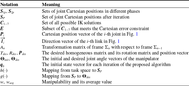
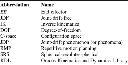
In this section, the proposed algorithm and relevant theoretical analyses are explained in detail to solve the IK of the SRS manipulator and remedy the problems encountered in RMP. Some important notations used in the proposed algorithm are listed in Table I, and the abbreviations frequently used in this paper are shown in Table II.
2.1. Mapping from task space to joint positions set
To prevent the JDP and algorithmic singularity induced by the Jacobian-based algorithm, the IK problem is solved by two mapping processes instead of directly calculating the joint angles. For the first mapping  $h\!\left ( \cdot \right ):\;{\mathbb{R}^{m}} \to{\textbf{S}}_{ P}$, the Cartesian position of the most important elbow joint (i.e.,
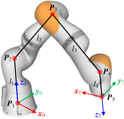
 ${\textbf{P}}_{3}$) can be derived by spatial iteration with the consideration of link length and joint limits. As shown in Fig. 1,
 ${\textbf{P}}_{1}$ and
 ${\textbf{P}}_{5}$ can be excluded from the iteration due to the fixed base and desired
 $EE$ pose. Thus, the determined target (i.e.,
 ${{\textbf{P}}}_{nt}$) is for
 ${\textbf{P}}_{4}$, and the iteration process is given by the following two phases:
 \begin{equation}{\textbf{S}}_{1p} \buildrel \Delta \over = \left \{ \begin{array}{l}{}^{i}{{\textbf{P}}^{\prime}}_{\!\!4} ={{{\textbf{P}}}_{nt}} ={{{{\textbf{P}}}_{des}} -{R_{ des}}{{\left [{{}_{n - 1}^{n}x,{}_{n-1}^ny,{}_{n-1}^{n}z} \right ]}^{T}}} \!\left ({n = 7} \right ) \\[5pt]{}^{i}{{\textbf{P}}^{\prime}}_{\!\!3} ={}^{i}{{\textbf{P}}^{\prime}}_{\!\!4} + \widehat{{}^{ i}{{\textbf{P}}^{\prime}}_{\!\!4}{{}^{i-1}{{\textbf{P}}}_{3}}} \cdot{l_{3}},\, \theta _{6}^{\min } \le{\theta _{6}} \le \theta _{ 6}^{\max }\, \mathbf{or} \,{}^i{{\textbf{P}}^{\prime}}_{\!\!3} ={}^{i}{{\textbf{P}}^{\prime}}_{\!\!4} +{R_{{\textbf{u}}_1}}\!\left ( \Delta{\varphi _{6}} \right ) \widehat{{}^{i}{{\textbf{P}}^{\prime}}_{\!\!4}{{}^{i-1}{{\textbf{P}}}_{3}}} \cdot{l_{3}} \\[5pt]{{}^{i}{{\textbf{P}}^{\prime}}_{\!\!2}} ={{}^{i}{{\textbf{P}}^{\prime}}_{\!\!3}} + \widehat{{{}^{ i}{{\textbf{P}}^{\prime}}_{\!\!3}}{{}^{i-1}{{\textbf{P}}}_{2}}} \cdot{l_{2}},\, \theta _{4}^{\min } \le{\theta _{4}} \le \theta _{4}^{\max }\, \mathbf{or}\,{{}^{i}{{\textbf{P}}^{\prime}}_{\!\!2}} ={{}^{i}{{\textbf{P}}^{\prime}}_{\!\!3}} +{R_{{\textbf{u}}_2}}\!\left ( \Delta{\varphi _{4}} \right ) \widehat{{{}^{i}{{\textbf{P}}^{\prime}}_{\!\!3}}{{}^{i-1}{{\textbf{P}}}_{2}}} \cdot{l_{2}}, \end{array} \right. \end{equation}
in which  ${{\textbf{u}}}_{1} = -\widehat{{{\textbf{l}}_{4}}} \times \widehat{{}^{ i}{{\textbf{P}}^{\prime}}_{\!\!4}{{}^{i-1}{{\textbf{P}}}_{3}}}$ and
 ${{\textbf{u}}}_{2} = \widehat{{}^{ i}{{\textbf{P}}^{\prime}}_{\!\!4}{{}^{i-1}{{\textbf{P}}}_{3}}} \times \widehat{{{}^{ i}{{\textbf{P}}^{\prime}}_{\!\!3}}{{}^{i-1}{{\textbf{P}}}_{2}}},$ and
 \begin{equation}{\textbf{S}}_{2p} \buildrel \Delta \over = \left \{ \begin{array}{l}{{}^{i}{{\textbf{P}}^{\prime\prime}}_{\!\!\!2}} ={\left [{0,0,\widehat{{{{\textbf{z}}}_{0}}} \cdot{l_{1}}} \right ]^{T}}\\[5pt]{{}^{i}{{\textbf{P}}^{\prime\prime}}_{\!\!\!3}} ={{}^{i}{{\textbf{P}}^{\prime\prime}}_{\!\!\!2}} + \widehat{{{}^{ i}{{\textbf{P}}^{\prime\prime}}_{\!\!\!2}}{{}^{i}{{\textbf{P}}^{\prime}}_{\!\!3}}} \cdot{l_{2}},\, \theta _{2}^{\min } \le{\theta _{2}} \le \theta _{2}^{\max }\, \mathbf{or}\,{}^{i}{{\textbf{P}}^{\prime\prime}}_{\!\!\!3} ={{}^{i}{{\textbf{P}}^{\prime\prime}}_{\!\!\!2}} +{R_{{\textbf{u}}_3}} \!\left ( \Delta{\varphi _{2}} \right ) \widehat{{{}^{i}{{\textbf{P}}^{\prime\prime}}_{\!\!\!2}}{{}^{i}{{\textbf{P}}^{\prime}}_{\!\!3}}} \cdot{l_{2}} \\[5pt]{{}^{i}{{\textbf{P}}^{\prime\prime}}_{\!\!4}} ={{}^{i}{{\textbf{P}}^{\prime\prime}}_{\!\!\!3}} + \widehat{{{}^{ i}{{\textbf{P}}^{\prime\prime}}_{\!\!\!3}}{{}^{i}{{\textbf{P}}^{\prime}}_{\!\!4}}} \cdot{l_{3}},\, \theta _{4}^{\min } \le{\theta _{4}} \le \theta _{4}^{\max }\, \mathbf{or}\,{{}^{i}{{\textbf{P}}^{\prime\prime}}_{\!\!4}} ={{}^{i}{{\textbf{P}}^{\prime\prime}}_{\!\!\!3}} +{R_{{\textbf{u}}_4}} \!\left ( \Delta{\varphi _{4}} \right ) \widehat{{{}^{i}{{\textbf{P}}^{\prime\prime}}_{\!\!\!3}}{{}^{i}{{\textbf{P}}^{\prime}}_{\!\!4}}} \cdot{l_{3}},\\[5pt] \end{array} \right. \end{equation}
Mathematical notations.

Schematic of the 7-DOF SRS manipulator, where  ${{\textbf{P}}}_{1}$ and
 ${{\textbf{P}}}_{5}$ indicate the base and end-effector positions, respectively, and
 ${{\textbf{P}}}_{i}\, (i=2,3,4)$ indicate the shoulder, elbow, and wrist positions in order.

in which  ${{{\textbf{u}}}}_{3} = \widehat{{{{{\textbf{z}}}}_{0}}} \times \widehat{{{}^{ i}{{\textbf{P}}^{\prime\prime}}_{\!\!\!2}}{{}^{i}{{\textbf{P}}^{\prime}}_{\!\!3}}}$ and
 ${{\textbf{u}}}_{4} = \widehat{{{}^{ i}{{\textbf{P}}^{\prime\prime}}_{\!\!\!2}}{{}^{i}{{\textbf{P}}^{\prime\prime}}_{\!\!\!3}}} \times \widehat{{{}^{i}{{\textbf{P}}^{\prime\prime}}_{\!\!\!3}}{{}^{ i}{{\textbf{P}}^{\prime}}_{\!\!4}}}$. When
 ${\theta _{i}}\!\left ({i = 2,4,6} \right )$ exceed joint limits,
 $ \Delta{\varphi _{i}}$ can be given by
 \begin{equation*} \Delta{\varphi _{i}} = \left \{{\begin{array}{*{20}{l}}{\theta _{i}^{\max } -{\theta _{i}}\quad if\quad \theta _{i}^{\max } \lt{\theta _{i}},} \\[5pt]{\theta _{i}^{\min } -{\theta _{i}}\quad if\quad{\theta _{i}} \lt \theta _{i}^{\min }.} \end{array}} \right. \end{equation*}
Abbreviations.

 $R_{{{\textbf{u}}}} \!\left ( \theta \right )$ represents the rotation around the axis
 ${\textbf{u}}$ by an angle
 $\theta$, which is given as
 \begin{equation*} R_{{{\textbf{u}}}} \!\left ( \theta \right ) = \!\left ({\cos \theta } \right )I + \!\left ({\sin \theta } \right ){\left [{{\textbf{u}}} \right ]_ \times } + \!\left ({1 - \cos \theta } \right )\!\left ({{{\textbf{u}}} \otimes{{\textbf{u}}}} \right ), \end{equation*}
where  $\left [{{\textbf{u}}} \right ]_ \times$ is the cross-product matrix of
 ${\textbf{u}}$.
 ${}^{ i}{{\textbf{P}}^{\prime}}_{\!\!n}$ and
 ${}^{i}{{\textbf{P}}^{\prime\prime}}_{\!\!\!n}$
 $\!\left ({2 \le n \le 4} \right )$ denote the position of
 ${{\textbf{P}}}_{n}$ in Fig. 1 after the first and second phases of the
 $i$-th iteration, respectively. The superscript
 ${}^{i-1}$ indicates the joint positions after the last iteration, or the initial joint positions when
 $i = 1$.
 $l_{n}$ is the length of the
 $n$-th link.
 ${{\textbf{P}}}_{des}$ and
 $R_{des}$ are the position vector and rotation matrix of
 $T_{des}$, respectively.
 $_{n - 1}^{n}x$,
 $_{n - 1}^{n}y$, and
 $_{n - 1}^{n}z$ are the
 $x$,
 $y$, and
 $z$ coordinates of the origin of frame
 $\Sigma _{n-1}$ in frame
 ${\Sigma _{n}} \!\left ({1 \le n \le 7} \right )$.
 $\widehat{{{\textbf{z}}}}_{n}$ is the
 $z$-axis unit vector of frame
 $\Sigma _{n}$, and
 $\widehat{{{\textbf{l}}_{4}}} = R_{des}{\left [{{}_{ n-1}^{ n}x,{}_{n-1}^{n}y,{}_{n-1}^{n}z} \right ]}^{T}\!\left ({n = 7} \right )$ is the desired direction vector of the end link.
Due to the determined direction vector of the end link and the fixed base,  ${}^i{{\textbf{P}}^{\prime}}_{\!\!4}$ and
 ${}^i{{\textbf{P}}^{\prime\prime}}_{\!\!\!2}$ should be corrected at the beginning of each phase. Equations (6)–(7) are cycled through until the distance between
 ${}^i{{\textbf{P}}^{\prime\prime}}_{\!\!4}$ and
 ${{\textbf{P}}}_{nt}$ meets the Cartesian error requirement and the angles between adjacent links are within joint limits. The
 $EE$ position is subsequently deduced by
 ${{{\textbf{P}}}_{5}} ={}^i{{\textbf{P}}^{\prime\prime}}_{\!\!4} + \widehat{{\textbf{l}}_{4}} \cdot l_{4}$. Set
 ${\textbf{S}}_{P} \buildrel \Delta \over = \left \{{{{{\textbf{P}}}_{3}},{{{\textbf{P}}}_{4}} \in{\textbf{S}}_{ 2p},{{{\textbf{P}}}_{ 1}},{{{\textbf{P}}}_{2}},{{{\textbf{P}}}_{5}}} \right \}$, containing all joint positions, is obtained after all iterations are completed. The advantages of the proposed algorithm are presented below, including theoretical analyses demonstrating its applicability to RMP.
 $(1)$ JDF motion: When there are no external disturbances, each iteration phase and the final configuration are predetermined before the first phase with the given initial state vector
 ${\textbf{q}}_{0} \in{\mathbb{R}^{7}}$,
 ${{\textbf{P}}}_{nt}$, and the Cartesian error. The initial joint positions (i.e.,
 ${}^{0}{{\textbf{P}}_{3}},{}^{0}{{\textbf{P}}_{4}}$) for the iteration of
 $h\!\left ( \cdot \right )$ can be obtained by forward kinematics with
 ${\textbf{q}}_{0}$. Once the above variables are determined, Eqs. (6)–(7) can guarantee the uniqueness of
 $h\!\left ( \cdot \right )$, that is,
 ${\textbf{S}}_{P}$ is unique for each IK query.
 $(2)$ Continuity of links’ configurations
 $\left \{{\overrightarrow{{\textbf{l}}_{1}},\overrightarrow{{\textbf{l}}_{2}},\overrightarrow{{\textbf{l}}_{3}},\overrightarrow{{\textbf{l}}_{4}} } \right \}$: For motion planning tasks, the Cartesian path can be interpolated as consecutive path points. Meanwhile, the pose of the end link can be guaranteed because
 ${{{\textbf{P}}}_{ 5}}$ is not involved in iterations. In addition, since
 $\overrightarrow{{\textbf{l}}_{1}}$ is a constant vector, the key to iteration is to find the elbow position (i.e.,
 ${{{\textbf{P}}}_{3}}$). Assuming
 ${{\textbf{P}}}_t$ and
 $\underline{{{\textbf{P}}}_{t}}={{\textbf{P}}}_{t} + \overrightarrow{\Delta{{\textbf{P}}}}$ are two consecutive path points that are treated as the targets for
 ${{\textbf{P}}}_{4}$, for the iteration of
 $\underline{{{\textbf{P}}}_{t}}$, the position change of
 ${{\textbf{P}}}_{3}$ in different phases can be summarized as
 \begin{equation} \left \{ \begin{array}{l} \underline{{}^{i}{P^{\prime}}_{\!\!3}} = \!\left ({{P_t} + \overrightarrow{\Delta p} } \right ) + \dfrac{{\underline{^{ i-1}{P_{3}}} - \!\left ({{P_{t}} + \overrightarrow{\Delta p} } \right )}}{{{{\left \|{\underline{^{i-1}{P_{3}}} - \!\left ({{P_{t}} + \overrightarrow{\Delta p} } \right )} \right \|}_{2}}}}{l_{3}}\\[20pt] \underline{{}^{i}{P^{\prime\prime}}_{\!\!\!3}} = \underline{{}^{i}{P^{\prime\prime}}_{\!\!\!2}} + \dfrac{{\underline{{}^{i}{P^{\prime}}_{\!\!3}} - \underline{{}^{ i}{P^{\prime\prime}}_{\!\!\!2}} }}{{{{\left \|{\underline{{}^{i}{P^{\prime}}_{\!\!3}} - \underline{{}^{i}{P^{\prime\prime}}_{\!\!\!2}} } \right \|}_{2}}}}{l_{2}}, \end{array} \right. \end{equation}
where the underline is used to indicate the iteration of  $\underline{{{{\textbf{P}}}_{t}}}$. Using Eq. (8) to compare with the iteration process of
 ${{\textbf{P}}}_{t}$, the variation can be quantified as
 \begin{equation} \left \{ \begin{array}{l} \underline{{}^{i}{{\textbf{P}}^{\prime}}_{\!\!3}} -{}^{i}{{\textbf{P}}^{\prime}}_{\!\!3} = \overrightarrow{\Delta{{\textbf{P}}}} +{l_{3}} \Biggl ( \dfrac{{\underline{^{i - 1}{{{\textbf{P}}}_{3}}} - \!\left ({{{{\textbf{P}}}_{t}} + \overrightarrow{\Delta{{\textbf{P}}}} } \right )}}{{{{\left \|{\underline{^{i - 1}{{{\textbf{P}}}_{3}}} - \!\left ({{{{\textbf{P}}}_{t}} + \overrightarrow{\Delta{{\textbf{P}}}} } \right )} \right \|}_{2}}}} - \dfrac{{{}^{i - 1}{{{\textbf{P}}}_{3}} -{{{\textbf{P}}}_{t}}}}{{{\left \|{{}^{i - 1}{{{\textbf{P}}}_{3}} -{{{\textbf{P}}}_{t}}} \right \|}_{2}}} \Biggr ) \\[20pt] \underline{{}^{i}{{\textbf{P}}^{\prime\prime}}_{\!\!\!3}} -{}^{i}{{\textbf{P}}^{\prime\prime}}_{\!\!\!3} ={l_{2}} \Biggl ({\dfrac{{\underline{{}^{i}{{\textbf{P}}^{\prime}}_{\!\!3}} - \underline{{}^{i}{{\textbf{P}}^{\prime\prime}}_{\!\!\!2}} }}{{{{\left \|{\underline{{}^{ i}{{\textbf{P}}^{\prime}}_{\!\!3}} - \underline{{}^{i}{{\textbf{P}}^{\prime\prime}}_{\!\!\!2}} } \right \|}_{2}}}} - \dfrac{{{}^{ i}{{\textbf{P}}^{\prime}}_{\!\!3} -{}^{i}{{\textbf{P}}^{\prime\prime}}_{\!\!\!2}}}{{{{\left \|{{}^{ i}{{\textbf{P}}^{\prime}}_{\!\!3} -{}^{ i}{{\textbf{P}}^{\prime\prime}}_{\!\!\!2}} \right \|}_{2}}}}} \Biggr ), \end{array} \right. \end{equation}
where  ${}^{i}{{\textbf{P}}^{\prime\prime}}_{\!\!\!2} = \underline{{}^{i}{{\textbf{P}}^{\prime\prime}}_{\!\!\!2}}$. Since
 $i$ starts from 1, the limit of Eq. (9) as
 $\overrightarrow{\Delta{{\textbf{P}}}}$ approaches
 $\mathbf{{0}}$ is given by
 \begin{equation} \left \{ \begin{array}{l} \mathop{\lim }\limits _{\overrightarrow{\Delta{{\textbf{P}}}} \to{\mathbf{{0}}}} \!\left ({\underline{{}^{ i}{{\textbf{P}}^{\prime}}_{\!\!3}} -{}^{i}{{\textbf{P}}^{\prime}}_{\!\!3}} \right ) ={\mathbf{{0}}} \\[11pt] \mathop{\lim }\limits _{\overrightarrow{\Delta{{\textbf{P}}}} \to{\mathbf{{0}}}} \!\left ({\underline{{}^{ i}{{\textbf{P}}^{\prime\prime}}_{\!\!\!3}} -{}^{i}{{\textbf{P}}^{\prime\prime}}_{\!\!\!3}} \right ) ={\mathbf{{0}}}. \end{array} \right. \end{equation}
As shown in Eq. (10), the minor movement of  ${{\textbf{P}}}_{4}$ in Cartesian space does not lead to the abrupt movement of
 ${{\textbf{P}}}_{3}$ with the same
 ${\textbf{q}}_{0}$. Equations (6)–(7) are the theoretical basis for generating smooth trajectories since they can be used to deduce continuous links’ configurations
 $\left \{{\overrightarrow{{\textbf{l}}_{1}},\overrightarrow{{\textbf{l}}_{2}},\overrightarrow{{\textbf{l}}_{3}},\overrightarrow{{\textbf{l}}_{4}} } \right \}$ for continuous path points.
 $(3)$ Guaranteed
 $EE$ pose:
 ${{\textbf{P}}}_{5}$ is excluded from the iteration to improve efficiency and induce only position error with no orientation error of
 $EE$, which eliminates the effect of repeated rotation of the 7th joint on other links compared to the pseudo-inverse algorithms. When performing repetitive tip rolling motions, such as screwing tasks, the elbow joint does not swing due to the repetitive rotation of the 7th joint, which reduces the risk of collisions and improves the safety of operations.
 $(4)$ Superior configurations: Generally, a higher
 $ w$ implies better singularity avoidance and adaptability during execution. In contrast with pseudo-inverse algorithms, Eqs. (6)–(7) can deduce the desired and natural configurations with higher
 $ w$. Furthermore, the solution process of the proposed algorithm is completed without using
 $J{\left ({\boldsymbol{\Theta }} \right )_{m \times n}}$, which compensates for the algorithmic singularity of the pseudo-inverse algorithms.
2.2. Mapping from joint positions set to the desired joint angle vector
An algorithmic solution implementing the mapping  $g \!\left ( \cdot \right ) :\;{\textbf{S}}_{P} \to{{\boldsymbol{\Theta }} _{ des}}$ is given in this subsection, in which
 ${{\boldsymbol{\Theta }} _{des}} \in{\mathbb{R}^{7}}$ is the desired IK joint angle vector. Note that the solution uniqueness and continuity derived from
 $h \!\left ( \cdot \right )$ can be retained in the process of
 $g \!\left ( \cdot \right )$.
 $\left |{{\theta _{i}}} \right | \!\left ({i = 2,4,6} \right )$ are first calculated by
 \begin{equation} \left |{{\theta _i}} \right | = \left |{\pi - \arccos \!\left ({\frac{{l_{j}^{2} + l_{j + 1}^{2} -{{\!\left ({{{\left \|{{\textbf{P}}_{j + 2}} -{{\textbf{P}}}_{j} \right \|}_{2}}} \right )}^{2}}}}{{2{l_{j}}{l_{j + 1}}}}} \right )} \right |, \end{equation}
where  $ i=2j$.
 $\left |{{\theta _{i}}} \right | \!\left ({i = 2,4,6} \right )$ will appear in the denominator of some equations and terminate calculations when one of them approaches or equals to zero. Hence, the realization of
 $g \!\left ( \cdot \right )$ can be classified into the following cases:
(1)  $\theta _{2}$,
 $\theta _{4}$, and
 $\theta _{6}$ are not equal to zero:
 $\theta _{1}$ is first calculated by
 \begin{equation}{\!\left ({{A_{1}}{A_{2}}{A_{3}}{{\left [{0,0,0,1} \right ]}^{T}}} \right )_{1,1}} ={{{\textbf{P}}}_{3,x}}, \end{equation}
where the subscripts  $i, j$ indicate the value of the
 $i$-th row and
 $j$-th column of the corresponding matrix, and
 $x$ indicates the
 $x$ coordinate of the corresponding joint Cartesian position.
 $A_{n}$ is the transformation matrix of frame
 $\Sigma _{n}$ with respect to frame
 $\Sigma _{n - 1}$. However, because the sign of
 $\theta _{2}$ cannot be determined temporally, the combinations of
 $\theta _{1}$ and
 $\theta _{2}$ should be filtered with the following equations
 \begin{equation} \theta _{i}^{\min } \le{\theta _{i}} \le \theta _{i}^{\max }, \end{equation}
 \begin{equation} \left |{1 - \widehat{{{\textbf{z}}}_{i}} \cdot \widehat{{{\textbf{l}}_{i/2 + 1}}}} \right | \le{\varepsilon _{ 1}}\, \big (i = 2,4,6 \big ), \end{equation}
where  ${\varepsilon _{1}} ={10^{-3}}$ is the defined tolerance. The solution set
 ${\textbf{C}}_{1,2}$ is defined as
 \begin{equation}{\textbf{C}}_{1,2} = \biggl \{ \!\left ({\theta _{1}},{\theta _{2}} \right ) \left | \textrm{Eqs}.\;(11)-(14)\right. \biggr \}. \end{equation}
Given the set  ${\textbf{C}}_{1,2}$,
 $\theta _{3}$ is calculated by
 \begin{equation}{\!\left ({{A_{3}}{A_{4}}{A_{5}}{{\left [{0,0,0,1} \right ]}^{T}}} \right )_{1,1}} ={\!\left ({A_{2}^{-1}A_{1}^{-1}{{\left [{{{{\textbf{P}}}_{4}},1} \right ]}^{T}}} \right )_{1,1}}. \end{equation}
Thus, the set  ${\textbf{C}}_{3,4}$ is defined as
 \begin{equation}{\textbf{C}}_{3,4} = \biggl \{ \!\left ({\theta _{3}},{\theta _{4}} \right ) \left | \textrm{Eqs}.\;(11),\, (13),\, (14),\, \textrm{and}\, (16) \right .\biggr \}. \end{equation}
Similarly,  $\theta _{5}$ is calculated by
 \begin{equation} \!\left ({A_{5}}{A_{6}}{A_{7}}{\left [{0,0,0,1} \right ]^{T}} \right )_{1,1} = \Big ( A_{4}^{-1}A_{3}^{-1}A_{ 2}^{ -1}A_{ 1}^{ -1}{T_{des}}{\left [{0,0,0,1} \right ]^{T}} \Big )_{1,1}, \end{equation}
which is used to define the set
 \begin{equation}{\textbf{C}}_{5,6} = \biggl \{ \!\left ({\theta _{5}},{\theta _{6}} \right ) \left | \textrm{Eqs}.\;(11),\, (13),\, (14),\, \textrm{and}\, (18)\right. \biggr \}. \end{equation}
Finally,  $\left |{{\theta _{7}}} \right |$, which is the angle between
 $\widehat{{\textbf{x}}_{6}}$ and
 $\widehat{{\textbf{x}}_{7}}$, is given by
 \begin{equation} \left |{{\theta _{7}}} \right | = \left |{\arccos \!\left ({\widehat{{\textbf{x}}_{6}} \cdot \widehat{{\textbf{x}}_{7}}} \right )} \right |, \end{equation}
where  $\widehat{{\textbf{x}}_{6}}$ and
 $\widehat{{\textbf{x}}_{7}}$ are the first three rows of the first columns of
 $\mathop \prod \limits _{n = 1}^{6}{A_{n}}$ and
 $T_{des}$, respectively. The set
 ${\textbf{C}}_{1-7}$, which includes all possible IK solutions, is expressed as
 \begin{equation}{\textbf{C}}_{1-7} = \biggl \{{\boldsymbol{\Theta }}\, \left | \textrm{Eqs}.\;(15),\, (17),\, (19),\, \textrm{and}\, (20)\right. \biggr \}. \end{equation}
 $(2)$
 $\left |{{\theta _{2}}} \right | \ne 0$,
 $\left |{{\theta _{4}}} \right | = 0$, and
 $\left |{{\theta _{6}}} \right | = 0$:
 ${\textbf{C}}_{1,2}$ is derived in the same way as in the first case. Due to
 $\left |{{\theta _{4}}} \right | = \left |{{\theta _{6}}} \right | = 0$, the analytical expressions for the remaining joint angles are difficult to obtain. Thus, the remaining solution processes can be formulated as the NLopt problem, which is given by
 \begin{equation} \begin{array}{l}{\textrm{min}}\, \Big [ \!\left ({\theta _{3}} -{\boldsymbol{\Theta }}_{init,3} \right )^{2} + \!\left ({\theta _{5}} -{\boldsymbol{\Theta }} _{init,5} \right )^{2} + \!\left ({\theta _{7}} -{\boldsymbol{\Theta }} _{init,7} \right )^{2} \Big ] \\[5pt]{\textrm{s.t.}}\, \left |{{\theta _{3}} +{\theta _{5}} +{\theta _{7}}} \right | = \left |{\arccos \!\left ({{{\!\left ({A_{ 2}^{ -1}A_{1}^{-1}{T_{des}}} \right )}_{1,1}}} \right )} \right |\, \textrm{and}\, \textrm{Eq}.\;(13), \end{array} \end{equation}
in which  ${\boldsymbol{\Theta }} _{init,i}$ denotes the
 $i$-th value of the initial joint angle vector of the manipulator (i.e.,
 ${\boldsymbol{\Theta }} _{init}$). The NLopt problem can be solved by the Sequential Least Squares Quadratic Programming algorithm. In this case,
 ${\textbf{C}}_{1-7}$ is defined as
 ${\textbf{C}}_{1-7} = \left \{{\boldsymbol{\Theta }} \left | \textrm{Eqs}.\;(15),\, (22),\, \textrm{and}\, \theta _{4} = \theta _{6} = 0 \right. \right \}$.
 $(3)$
 $\left |{{\theta _{2}}} \right | = 0$,
 $\left |{{\theta _{4}}} \right | \ne 0$, and
 $\left |{{\theta _{6}}} \right | = 0$: The solutions to
 $\left |{{\theta _{1}} +{\theta _{3}}} \right |$ and
 $\left |{{\theta _{5}} +{\theta _{7}}} \right |$ are formulated as
 \begin{equation} \begin{array}{l}{\textrm{min}}\, \Big [ \big ({\theta _{1}} -{\boldsymbol{\Theta }} _{init,1} \big )^{2} + \big ({\theta _{3}} -{\boldsymbol{\Theta }} _{init,3} \big )^{2} \Big ] \\[5pt]{\textrm{s.t.}}\, \left |{{\theta _{1}} +{\theta _{3}}} \right | = \left |{\arccos \!\left ({\frac{{{T_{ des,1,3}}}}{{s_{4}}}} \right )} \right |\, \textrm{and}\,{\textrm{Eq}}.\;(13), \end{array} \end{equation}
where  $s_{i}$ is the abbreviation of
 $\sin{\theta _{i}}$, and
 \begin{equation} \begin{array}{l}{\textrm{min}}\, \Big [ \big ({\theta _{5}} -{\boldsymbol{\Theta }} _{init,5} \big )^{2} +{\big ({\theta _{7}} -{\boldsymbol{\Theta }} _{init,7} \big )^{2}} \Big ] \\[5pt]{\textrm{s.t.}}\, \left |{{\theta _{5}} +{\theta _{7}}} \right | = \left |{\arccos \!\left ({\frac{T_{ des,3,1}}{-s_{4}}} \right )} \right | \, \textrm{and}\,{\textrm{Eq}}.\;(13). \end{array} \end{equation}
Equation (14) is utilized to eliminate some wrong combinations of  $\!\left ({{\theta _{1}} +{\theta _{3}}} \right )$ and
 ${\theta _{ 4}}$.
 ${\textbf{C}}_{1-7}$ is thus given by
 ${\textbf{C}}_{1-7} = \{{\boldsymbol{\Theta }}\, \left | \textrm{Eqs}.\;(11),\, (14),\, (23),\, (24)\right .,\, \textrm{and}\,{\theta _{4} = \theta _{6} = 0}\}$.
 $(4)$
 $\left |{{\theta _{2}}} \right | = 0$,
 $\left |{\theta _{4}} \right | = 0$, and
 $\left |{\theta _{6}} \right | \ne 0$: Using Eq. (11),
 $\left |{\theta _{7}} \right |$ can be calculated by
 \begin{equation} \left |{{\theta _{7}}} \right | = \left |{\arccos \!\left ({\frac{T_{des,3,1}}{-s_{6}}} \right )} \right |. \end{equation}
Then,  ${\textbf{C}}_{6,7}$ is defined as
 \begin{equation}{\textbf{C}}_{6,7} = \biggl \{ \!\left ({\theta _{6}},\,{\theta _{7}} \right ) \left |{\textrm{Eqs}}.\;(11),\, (25),\,{\textrm{and}}\right. \left |{\widehat{{{\textbf{z}}}_{5}} \cdot \widehat{{\textbf{l}}_{4}}} \right | \le{\varepsilon _{ 1}} \biggr \}. \end{equation}
The solution to  $\theta _{1}$,
 $\theta _{3}$, and
 $\theta _{5}$ is formulated as
 \begin{equation} \begin{array}{l}{\textrm{min}}\, \Big [ \big ({\theta _{1}} -{\boldsymbol{\Theta }} _{init,1} \big )^{2} +{ \big ({\theta _{3}} -{\boldsymbol{\Theta }} _{init,3} \big )^{2}} +{{\big ({{\theta _{5}} -{{\boldsymbol{\Theta }} _{init,5}}} \big )}^{2}} \Big ] \\[5pt]{\textrm{s.t.}}\, \left |{\theta _{1}} +{\theta _{3}} +{\theta _{5}} \right | = \left | \arccos \!\left ( \!\left ({T_{ des}A_{ 7}^{ - 1}A_{6}^{- 1}} \right )_{1,1} \right ) \right |\, \textrm{and}\, \textrm{Eq}.\;(13). \end{array} \end{equation}
Then, we can obtain  ${\textbf{C}}_{1-7} = \left \{{\boldsymbol{\Theta }} \left | \textrm{Eqs}.\;(26),\, (27),\,{\textrm{and}}\right .{\theta _{2}} ={\theta _{4}} = 0 \right \}$.
 $(5)$
 $\left |{\theta _{2}} \right | \ne 0$,
 $\left |{{\theta _{4}}} \right | \ne 0$, and
 $\left |{{\theta _{6}}} \right | = 0$: The procedures in the first case are repeated until the sets
 ${\textbf{C}}_{1,2}$ and
 ${\textbf{C}}_{3,4}$ are obtained. Then, the solution to
 ${\theta _{5}}$ and
 ${\theta _{7}}$ can be written as
 \begin{equation} \begin{array}{l}{\textrm{min}}\, \Big [ \big ({\theta _{5}} -{\boldsymbol{\Theta }} _{init,5} \big )^{2} + \!\left ({\theta _{7}} -{\boldsymbol{\Theta }} _{init,7} \right )^{2} \Big ]\\[5pt]{\textrm{s.t.}}\, \left |{{\theta _{5}} +{\theta _{7}}} \right | = \left |{\arccos \!\left ({{{\!\left ({A_{ 4}^{ -1}A_{ 3}^{ -1}A_{2}^{-1}A_{1}^{-1}{T_{des}}} \right )}_{1,1}}} \right )} \right |\, \textrm{and}\,{\textrm{Eq}}.\;(13). \end{array} \end{equation}
Similarly,  ${\textbf{C}}_{1-7}$ is thus defined as
 ${\textbf{C}}_{1-7} = \left \{{\boldsymbol{\Theta }}\, \left | \textrm{Eqs}.\;(15),\, (17),\, (28),\,{\textrm{and}}\right .{\theta _{6}} = 0 \right \}.$
 $(6)$
 $\left |{{\theta _{2}}} \right | = 0$,
 $\left |{{\theta _{4}}} \right | \ne 0$, and
 $\left |{{\theta _{6}}} \right | \ne 0$: Using Eq. (11) and
 $T_{des}$,
 $\left |{{\theta _{5}}} \right |$ should be calculated first by
 \begin{equation} \left |{{\theta _{5}}} \right | = \left |{\arccos \!\left ({\frac{{c_{4} c_{6} -{T_{des,3,3}}}}{{s_{4}s_{6}}}} \right )} \right |, \end{equation}
where  $c_{i}$ is the abbreviation of
 $\cos{\theta _{i}}$. Given Eq. (29),
 ${\textbf{C}}_{5,6}$ is defined as
 \begin{equation}{\textbf{C}}_{5,6} = \biggl \{ \!\left ({\theta _{5}},{\theta _{6}} \right )\, \left | \textrm{Eqs}.\;(11),\, (13),\, \textrm{and}\, (29) \right .\biggr \}. \end{equation}
Then,  $\theta _{7}$ is obtained by solving
 \begin{equation}{s_{4}}{s_{5}}{s_{7}} - \!\left ({{c_{4}}{s_{6}} +{c_{5}}{c_{6}}{s_{4}}} \right ){c_{7}} ={T_{des,3,1}} \end{equation}
with the constraints of Eqs. (14), (30), and  $ \left |{1 + \widehat{{\textbf{y}}_{3}} \cdot \widehat{{\textbf{l}}_{2}}} \right | \le{\varepsilon _{1}}$. After deriving the set
 \begin{equation}{\textbf{C}}_{4,5,6,7} = \biggl \{ \!\left ({\theta _{4}},{\theta _{5}},{\theta _{6}},{\theta _{7}} \right )\, \left | \textrm{Eqs}.\;(11),\, (13),\, (30),\,{\textrm{and}}\, (31)\right. \biggr \}, \end{equation}
the solution to  $\theta _{1}$ and
 $\theta _{3}$ is formulated as
 \begin{equation} \begin{array}{l}{\textrm{min}}\, \Big [ \big ({\theta _{1}} -{\boldsymbol{\Theta }} _{init,1} \big )^{2} +{\big ({\theta _{3}} -{\boldsymbol{\Theta }} _{init,3} \big )^{2}} \Big ] \\[5pt]{\textrm{s.t.}}\, \left |{{\theta _{1}} +{\theta _{3}}} \right | = \left |{\arccos \!\left ({{{\!\left ({{T_{ des}}A_{ 7}^{ -1}A_{ 6}^{-1}A_{5}^{-1}A_{4}^{-1}} \right )}_{1,1}}} \right )} \right |\, \textrm{and}\, \textrm{Eq}.\;(13). \end{array} \end{equation}
Finally,  ${\textbf{C}}_{1-7}$ is defined as
 ${\textbf{C}}_{1-7} = \{ \Theta \, \left | \textrm{Eqs}.\;(32),\, (33),\, \textrm{and}\, \right .{\theta _{2}} = 0 \}$.
 $(7)$
 $\left |{{\theta _{2}}} \right | \ne 0$,
 $\left |{{\theta _{4}}} \right | = 0$, and
 $\left |{{\theta _{6}}} \right | \ne 0$: Given Eq. (11),
 $\theta _{7}$ can be calculated first with
 \begin{equation} \left |{{\theta _{7}}} \right | = \left |{\arccos \!\left ({\frac{{{{\!\left ({A_{2}^{-1}A_{1}^{-1}{T_{des}}} \right )}_{ 3,1}}}}{{-s_{ 6}}}} \right )} \right | \end{equation}
and  ${\textbf{C}}_{1,2}$, which is similarly defined as in the first case. Then,
 ${\textbf{C}}_{6,7}$ is defined as
 \begin{equation}{\textbf{C}}_{6,7} = \biggl \{ \!\left ({\theta _{6}},{\theta _{7}}\right ) \left |{\textrm{Eqs}}.\;(11),\, (34),\,{\textrm{and}}\, \right. \left |{\widehat{{{\textbf{z}}}_{5}} \cdot \widehat{{\textbf{l}}_{4}}} \right | \le{\varepsilon _{1}} \biggr \}. \end{equation}
Thus, the solution to  $\theta _{3}$ and
 $\theta _{5}$ can be formulated as
 \begin{equation} \begin{array}{l}{\textrm{min}}\, \Big [ \big ({\theta _{3}} -{\boldsymbol{\Theta }} _{init,3} \big )^{2} + \big ({\theta _{5}} -{\boldsymbol{\Theta }} _{init,5} \big )^{2} \Big ] \\[5pt]{\textrm{s.t.}}\, \left |{{\theta _{3}} +{\theta _{5}}} \right | = \left |{\arccos \!\left ({{{\!\left ({A_{2}^{ -1}A_{ 1}^{ -1}{T_{des}}A_{7}^{ - 1}A_{6}^{-1}} \right )}_{1,1}}} \right )} \right |\, \textrm{and}\, \textrm{Eq}.\;(13). \end{array} \end{equation}
 ${\textbf{C}}_{1-7}$ is then defined as
 ${\textbf{C}}_{1-7} = \{{\boldsymbol{\Theta }}\, \left | \textrm{Eqs}.\;(15),\, (35),\, (36),\, \textrm{and}\right .{\theta _{4}} = 0 \}$.
 $(8)$
 $\left |{{\theta _{2}}} \right | = 0$,
 $\left |{{\theta _{4}}} \right | = 0$, and
 $\left |{{\theta _{6}}} \right | = 0$: The solution to the remaining joint angles can be formulated as
 \begin{equation} \begin{array}{l}{\textrm{min}}\, \Big [ \big ({\theta _{1}} -{{\boldsymbol{\Theta }} _{init,1}} \big )^{2} + \big ({\theta _{3}} -{\boldsymbol{\Theta }} _{init,3} \big )^{2} +{\!\left ({\theta _{5}} -{\boldsymbol{\Theta }} _{init,5} \right )}^{2} + \!\left ({\theta _{7}} -{\boldsymbol{\Theta }} _{ init,7} \right )^{2} \Big ]\\[5pt]{\textrm{s.t.}}\, \big |{\theta _{1}} +{\theta _{3}} +{\theta _{5}} +{\theta _{7}} \big | = \big | \arccos \!\left ({{T_{ des,1,1}}} \right ) \big |\, \textrm{and}\, \textrm{Eq}.\;(13). \end{array} \end{equation}
Hence,  ${\textbf{C}}_{1-7}$ is given as
 ${\textbf{C}}_{1-7} = \{{\boldsymbol{\Theta }}\, \left |{{\theta _{2}} ={\theta _{4}} ={\theta _{6}} = 0}\, \textrm{and}\, \textrm{Eq}.\;(37)\right. \}$.
No matter which case is performed,  ${\textbf{C}}_{1-7}$ will eventually be defined to obtain
 ${\boldsymbol{\Theta }} _{ des}$. Traversing
 ${\textbf{C}}_{1-7}$ with
 \begin{equation} \begin{array}{l}{T_{temp}}\!\left ({\boldsymbol{\Theta }} \right ) ={A_{1}}{A_{2}} \cdots{A_{7}} = \left [{\begin{array}{*{20}{c}}{{R_{temp}}}\;\;\;\;&{{{{\textbf{P}}}_{temp}}}\\[5pt] 0\;\;\;\;&1 \end{array}} \right ], \end{array} \end{equation}
each  ${T_{temp}}\!\left ({\boldsymbol{\Theta }} \right )$ can be used to compare with
 $T_{des}$ to derive the set
 ${\textbf{E}} \subseteq{\textbf{C}}_{1-7}$, which is defined as
 \begin{equation}{\textbf{E}} = \biggl \{{\boldsymbol{\Theta }} \;:\,\left ({{\varepsilon _{rot}} +{\varepsilon _{pos}}} \right ) \le{\varepsilon _{tol}},\,{\boldsymbol{\Theta }} \in{{\textbf{C}}_{1-7}} \biggr \}. \end{equation}
The rotation error  $\!\left ( \textrm{i.e.,}\, \varepsilon _{rot}\right )$ and position error
 $\!\left ( \textrm{i.e.,}\, \varepsilon _{ pos}\right )$ can be calculated by
 \begin{equation} \begin{array}{l}{\varepsilon _{rot}} = \arccos \!\left ({\frac{{tr\left ({R_{temp}^{-1}{R_{des}}} \right ) - 1}}{2}} \right )\,{\textrm{and}} \,{\varepsilon _{pos}} = dist\!\left ({{{{\textbf{P}}}_{temp}},{{{\textbf{P}}}_{des}}} \right ) ={\left \|{{{{\textbf{P}}}_{ temp}} -{{{\textbf{P}}}_{des}}} \right \|_{2}}, \end{array} \end{equation}
respectively. Meanwhile,  ${\boldsymbol{\Theta }} _{des}$ can be found by
 \begin{equation}{{\boldsymbol{\Theta }} _{des}} = \mathop{\arg \min }\limits _{{\boldsymbol{\Theta }} \in{\textbf{E}}}{\left \|{{\boldsymbol{\Theta }} -{{\boldsymbol{\Theta }} _{init}}} \right \|_{1}}. \end{equation}
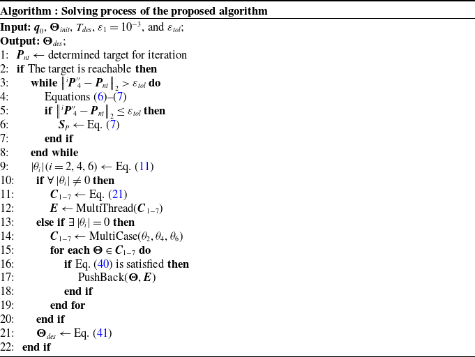
Solving process of the proposed algorithm

Some joint angle elements in  ${\boldsymbol{\Theta }}$ and
 ${\boldsymbol{\Theta }} _{init}$ can be omitted to reduce the variation in other joints and obtain other desired solutions. Although
 $\left |{{\theta _{i}}} \right | \!\left ({i = 2,4,6} \right )$ are rounded to a given number of places,
 ${\textbf{C}}_{1-7}$ in the first case has the most elements, and the multi-threaded solvers are required to boost the computational process to obtain
 ${\boldsymbol{\Theta }} _{des}$. For other cases, multithreading may reduce the efficiency of computation. The procedure of the proposed algorithm is outlined in Algorithm 1, where MultiThread is programmed to realize Eqs. (38)–(40) with multithreading, and MultiCase implements the solutions to Cases 2–8.
3. Simulation and performance
The performance of the proposed algorithm is quantified in this section by applying it to the KUKA LBR iiwa 14 R820. Meanwhile, KDL and TRAC-IK are adopted as baselines for comparisons. The joint-drift and screwing simulations are performed using the proposed algorithm on the KUKA manipulator. The ability of the proposed algorithm to deduce superior solutions is also demonstrated.
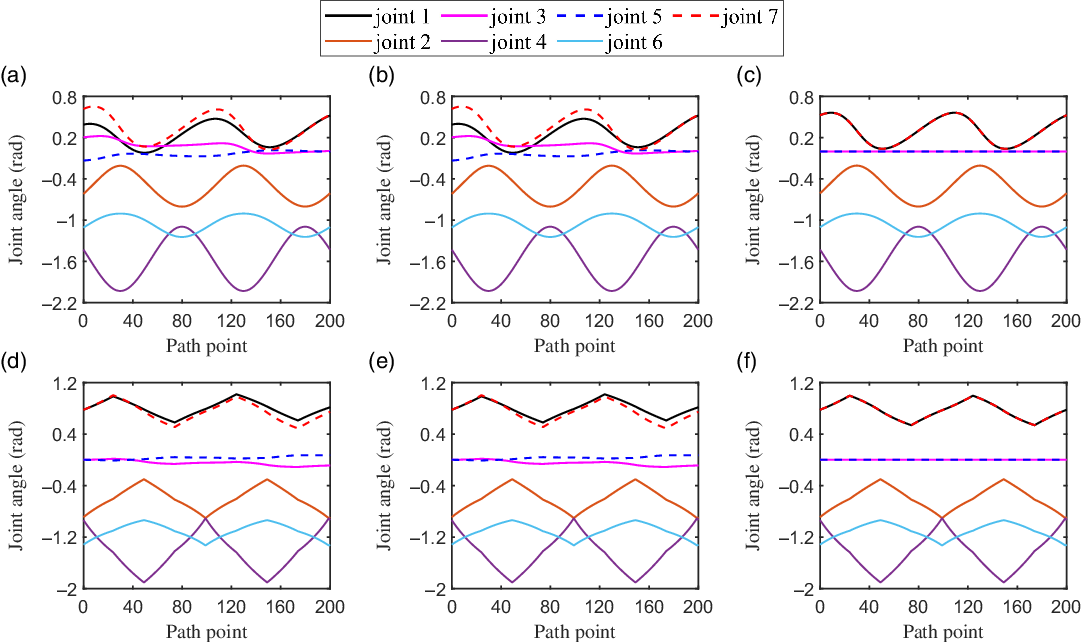
The joint trajectories synthesized by (a), (d) KDL, (b), (e) TRAC-IK, and (c), (f) the proposed algorithm, respectively, when the tip of the KUKA manipulator traces the circle (first row) and square paths (second row) twice.

In this section, the initial state for each iteration of the proposed algorithm is  ${{\textbf{q}}_{0}} = [0,0,0,0,0,0,0]$ rad, that is,
 ${}^{0}{{\textbf{P}}_{i}} ={[0,0,\sum \nolimits _{n = 1}^{i-1}{{l_{n}}} ]}^{T} \!\left ({i = 3,4} \right )$. Before performing the simulations below, the solve rate and average solve time of the proposed algorithm are first verified by a quantitative test with
 $ 10,000$ random samples, which are constructed by reachable manipulator configurations. When the Cartesian error is
 $ 10^{-6}$, the results show that the solve rate is
 $ 99.93 \%$ and the average solve time is
 $ 0.59$ ms, which satisfy our requirements for stability and real-time ability of the IK algorithm. All simulations in this section are performed with the
 $ 10^{-6}$ Cartesian error constraint and implemented in C++ on a computer with an Intel Core i3-9100 CPU @ 3.6 GHz
 $ \times$ 4 and 15 GB RAM.
3.1. Joint-drift simulations
In this subsection, the joint-drift simulations are performed on the KUKA manipulator using KDL, TRAC-IK, and the proposed algorithm, respectively. The  $EE$ of the KUKA manipulator must trace the given circle and square paths repeatedly, where the radius of the circle is
 $0.14$ m and the side length of the square is
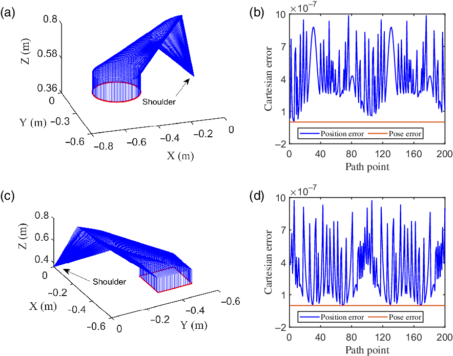
 $0.2$ m. Both paths have been interpolated to 100 path points. Figure 2 illustrates the joint trajectories synthesized by the above three algorithms when tracing the given circular (Fig. 3(a)) and square (Fig. 3(c)) paths twice, in which the initial joint angles are
 ${\boldsymbol{\Theta }_{init}}$
 $ = [0.526$,
 $ -0.609$,
 $ 0$,
 $ -1.431$,
 $ 0$,
 $ - 1.102$,
 $0.526]$ rad and
 ${\boldsymbol{\Theta }_{init}}$
 $= [0.777$,
 $ - 0.888$,
 $ 0$,
 $ -0.936$,
 $ 0$,
 $ -1.316$,
 $ 0.777]$ rad, respectively. As shown in Fig. 2(a), (b), (d), and (e), the drifts of joints 1, 3, 5, and 7 can be clearly observed when using KDL and TRAC-IK. Contrastively, the joint trajectories deduced by the proposed algorithm all return to their initial states in Fig. 2(c) and (f), which indicates the JDF motion is realized. Moreover, Fig. 3(a) and (c) illustrate the tracking performance of the proposed algorithm, in which the
 $ EE$ can successfully trace the specified paths (red lines) with good continuity of configurations (blue lines). Using Eq. (40) to generate variation curves of the position error and pose error, it can be observed from Fig. 3(b) and (d) that the maximum value of position error is less than
 $ 10^{-6}$ and the pose error is always zero, both of which meet the error constraint and demonstrate the theoretical analyses in Section 2.1.
(a), (c) Manipulator motion trajectory profiles and the (b), (d) Cartesian errors generated by the proposed algorithm when tracing the given circular (first row) and square (second row) paths twice.

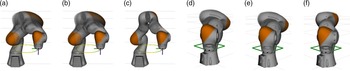
The configurations of the KUKA manipulator synthesized by (a), (d) KDL, (b), (e) TRAC-IK, and (c), (f) the proposed algorithm, respectively, when passing the same point in the 20-cycle circular and square tracing tasks.

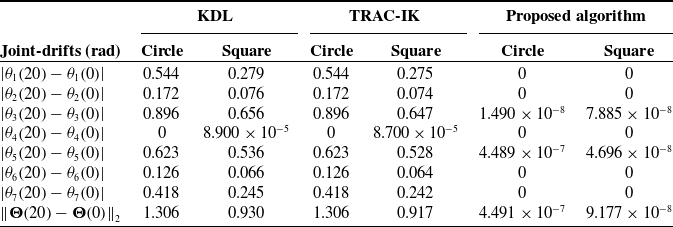
As the tip of the KUKA manipulator continues to trace the paths, some of the joint angles drift to their fixed values until the path is closed in C-space when using KDL and TRAC-IK. Figure 4 displays the whole joint-drift process induced by KDL and TRAC-IK, and the joint angle repeatability guaranteed by using the proposed algorithm. Table III lists the detailed simulation data, in which the joint-drift ( $\left \|{\boldsymbol{\Theta } \!\left ({20} \right ) - \boldsymbol{\Theta } \!\left ( 0 \right )} \right \|_{2}$) synthesized by the proposed algorithm in different tracing tasks is
 $4.491 \times{10^{-7}}$ and
 $ 9.177 \times 10^{-8}$ rad, which are significantly smaller than those of KDL and TRAC-IK. For the circular and square tracing tasks with 2000 path points, the average solution time of the proposed algorithm is
 $ 0.243$ and
 $ 0.239$ ms, respectively. Notably, the JDF motion is realized by the proposed algorithm with only three parameters, that is,
 ${{\textbf{q}}_{0}}$,
 ${\textbf{P}}_{nt}$, and Cartesian error requirement, which omit the time-consuming tuning process. In summary, the simulation results substantiate the effectiveness of the proposed algorithm when applied to the KUKA manipulator to perform real-time JDF motion.
Comparisons of joint-drifts among KDL, TRAC-IK, and the proposed algorithm when the tip traces the two different paths twenty times.

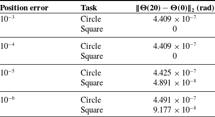
Finally, since the proposed algorithm does not induce pose error, the effects of position error on joint-drift (i.e.,  $\left \|{\boldsymbol{\Theta } \!\left ({20} \right ) - \boldsymbol{\Theta } \!\left ( 0 \right )} \right \|_{2}$) are verified. As shown in Table IV, position error causes a minor change in joint-drift within the computation accuracy. This effect is insignificant when compared to the change in magnitude of the position error.
The effects of position error on joint-drift when the proposed algorithm is applied to different tracing tasks.

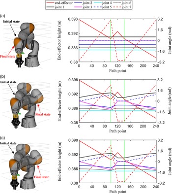
Screwing simulation results using (a) the proposed algorithm, (b) TRAC-IK, and (c) KDL, respectively. For each row, the first column shows the initial and final configurations, and the second column shows the joint trajectories and the variations of  $EE$ height relative to the base.

3.2. Screwing simulation
The 2F-85 ROBOTIQ gripper and KUKA manipulator are used to perform the screwing simulation. Meanwhile, the connector is designed to connect the KUKA flange and the ROBOTIQ gripper, as shown in Fig. 5(a). The initial joint angle vector is  ${\boldsymbol{\Theta }_{init}} = [0.527, -0.609,0, -1.430, 0, -1.102, -3.0]$ rad. Due to the joint limit of
 $\theta _{7}$, the height of
 $EE$ needs to be adjusted to reset
 $\theta _{ 7}$ during the screwing process. Hence, the above process is divided into the following stages:
-
(1)
$EE$ is first planned to finish the motion in which the gripper rotates and drops in height until reaching the limit of $\theta _{7}$. -
(2)
$EE$ moves up to reset $\theta _{7}$ and then returns to the height at the end of the first stage. -
(3) Repeat the motion of the first stage.


To complete the solution for each path point, the timeout is  $ 15$ ms and the running type of TRAC-IK is “Distance,” which means TRAC-IK runs the full timeout and then returns the solution that minimizes the sum of squared error from the seed. As shown in Fig. 5, the green dotted lines indicate the different stages, from which the variations of
 $EE$ height clearly show the screwing processes. In contrast with TRAC-IK and KDL, the proposed algorithm can rotate the 7th joint significantly as desired and with little variation in other joint angles during the process. Both KDL and TRAC-IK induce an intense swing of the elbow joint, which increases the risk of colliding with nearby objects and people. Moreover, for 664 path points, the average solution time of the proposed algorithm is
 $ 0.223$ ms.
3.3. Manipulability performance evaluation
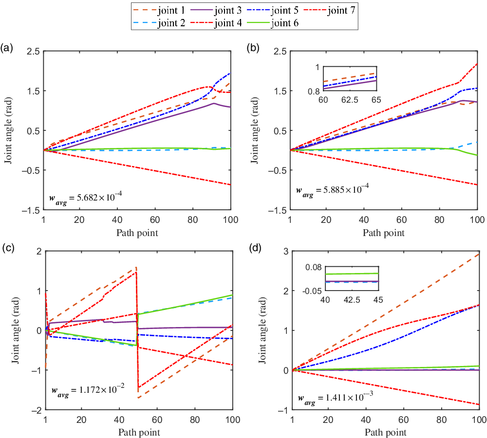
In this subsection, the simulation path points in Cartesian space are obtained by calculating the linear path between the target configuration in C-space and the zero position using forward kinematics, where the target configuration is selected randomly in the low manipulability region of the KUKA manipulator. The average values of manipulability  ${w_{avg}}$ are obtained by solving the path with the three algorithms and used as the measure indexes. Moreover, both the running types “Manip1” and “Distance” of TRAC-IK are used to solve the path, in which “Manip1” means TRAC-IK runs the full timeout and then returns the solution that maximizes
 $ w$. The timeout is
 $10$ ms to guarantee the solution stability of KDL and TRAC-IK. The target configuration is
 ${\boldsymbol{\Theta }_{end}} = [0.144, -0.027, 2.805, -0.869, 1.610, 0.112, 1.649]$ rad. As shown in Fig. 6(c), although the max
 $ w_{avg}$ is derived, the oscillatory joint trajectories are generated when using the “Manip1” type of TRAC-IK, which is not applicable to continuous motion. Figure 6(d) indicates that the proposed algorithm can generate smooth trajectories with a higher
 ${w_{avg} = 1.411 \times 10^{-3}}$, which is approximately triple that of KDL (Fig. 6(a)) and the “Distance” type of TRAC-IK (Fig. 6(b)). The average solution time of the proposed algorithm is
 $ 5.543$ ms, and the simulation results substantiate the above statements that the proposed algorithm can produce superior configurations relative to KDL and TRAC-IK.
Joint trajectories derived from manipulability simulations using (a) KDL, TRAC-IK with the running types (b) “Distance” and (c) “Manip1”, and (d) the proposed algorithm, respectively.

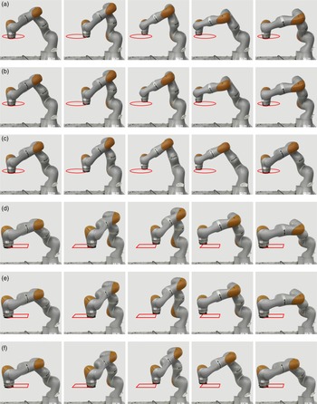
The experiments for tracking the circle (first three rows) and square (last three rows) paths are performed on the KUKA manipulator using (a), (d) KDL, (b), (e) TRAC-IK, and (c), (f) the proposed algorithm, respectively. The KUKA manipulator begins with the initial point (first column), moves counterclockwise through the path points (middle three columns), and finally gets back to the start point (last column).

4. Experiment verification
The experiments in this section are designed to verify the simulation results in Sections 3.1 and 3.2, as well as the practical feasibility of the proposed algorithm. Thus, the relevant procedures of the experiments are basically the same as those of simulations. Notably, the proposed algorithm is implemented on the KUKA LBR iiwa 14 R820 manipulator with the  $ 10^{-6}$ Cartesian error constraint to solve all path points in real time.
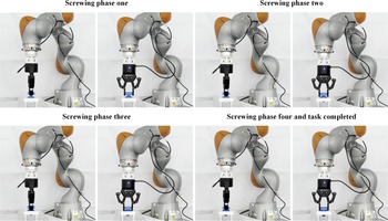
Snapshots of the screwing assembling experiment using the proposed algorithm with the KUKA manipulator and the 2F-85 ROBOTIQ gripper. The 7th joint rotates from -3 rad to 1.714 rad, and the  $EE$ moves down during each screwing process, after which the 7th joint must be reset to -3 rad, and the
 $EE$ moves upwards as required.

4.1. Experiment A: Circular and square path tracking
In order to verify the reliability of joint-drift simulation results, the physical experiments are performed on the KUKA manipulator using the above three baselines. For the circular and square path tracing, the initial joint angles of the KUKA manipulator are  ${\boldsymbol{\Theta } _{init}} = [0.527, -0.609, 0, 1.430, 0, -1.102, 0.527]$ rad and
 ${\boldsymbol{\Theta }_{init}} = [0.777, - 0.888,0, 0.936,0, -1.316,0.777]$ rad, respectively. The initial state for each iteration of the proposed algorithm is
 ${{\textbf{q}}_{0}} = [0,0,0,0,0,0,0]$ rad. As shown in Fig. 7(c) and (f), the tip of the KUKA manipulator can track the red paths accurately and steadily when using the proposed algorithm. Meanwhile, the continuity of configurations can be guaranteed. After 20-cycle tracking tasks, the initial and final configurations of the KUKA manipulator are identical. On the contrary, as shown in the last columns of Fig. 7(a), (b), (d), and (e), the JDP caused by KDL and TRAC-IK can be clearly observed. Thus, the feasibility of the proposed algorithm to generate JDF motion with guaranteed Cartesian precision is experimentally verified. All the experimental processes can be found in the accompanying video (See Supplementary materials).
4.2. Experiment B: Screwing assembling
This subsection presents the screwing experiment performed by the KUKA manipulator and 2F-85 ROBOTIQ gripper to validate the simulation results derived from the proposed algorithm. The initial joint angles of the KUKA manipulator are  ${\boldsymbol{\Theta }_{init}} = [0.527, -0.609,0, 1.430, 0, -1.102, -3.0]$ rad, and the initial state for each iteration of the proposed algorithm is
 ${{\textbf{q}}_{0}} = [0,0,0,0,0,0,0]$ rad. In this experiment, the allowable motion range of the seventh joint is set from
 $ -3$ to
 $ 1.714$ rad. As shown in Fig. 8, the screwing experiment is divided into four phases. When the seventh joint reaches
 $ 1.714$ rad in the second and fourth columns of Fig. 8, the
 $ EE$ should be raised to reset the seventh joint and the gripper should be released. The KUKA manipulator finished the whole screwing process with minor variations in other joints and no swing of the elbow, which is presented in detail in the accompanying video (See Supplementary materials). In addition, it can be observed that the bolt can be accurately screwed into the hole with the guarantee of
 $ EE$ precision by the proposed algorithm.
5. Conclusion
In this paper, an IK algorithm to solve the redundancy resolution and the RMP of the SRS manipulators has been presented. The proposed algorithm first implements the mapping from the task space to the joint Cartesian positions and then deduces the desired joint angles from the second mapping. Beyond that, the proposed algorithm can be applied to real-time applications and provide a high solve rate, which has been demonstrated by a quantitative IK test on the KUKA manipulator. In contrast with KDL and TRAC-IK, simulations and experiments have been performed on the KUKA manipulator to verify that the proposed algorithm can remedy the joint-drift problems and elbow swing. Meanwhile, the  $EE$ accuracy and the continuity of the trajectory can be guaranteed simultaneously. Moreover, when compared to the other two baselines, the proposed algorithm can generate superior configurations with higher manipulability.
Future work will focus on extending this algorithm to more types of manipulators. A more computationally efficient algorithm that does not need classification during the second mapping is worth investigating when applied to hyper-redundant manipulators. Some constraints on obstacle avoidance can be imposed in the first mapping to take advantage of the kinematic redundancy of redundant manipulators. Notably, the initial value has a significant impact on solution time for different IK queries, which is worth optimizing and further discussion.
Supplementary materials
To view supplementary material for this article, please visit https://doi.org/10.1017/S0263574722001370.
Authors’ contributions
None.
Financial support
This work has been supported by the National Natural Science Foundation of China [Project Number: 92148203] and Self-Planned Task [NO. SKLRS202201A01] of State Key Laboratory of Robotics and System.
Conflicts of interest
The authors declare that they have no conflict of interests.
Ethical considerations
None.