1. INTRODUCTION
To capture human body motion in an ambulatory situation without the need for external emitters or cameras, it is possible to use inertial sensors such as gyroscopes, ultrasonic velocity sensors, radar altimeters and accelerometers to estimate the relative position and orientation (Morris (Reference Morris1973), Bonato (Reference Bonato2005), Foxlin (Reference Foxlin1996), Bachmann (Reference Bachmann2000), Molet, Boulic, and Thalmann (Reference Molet, Boulic and Thalmann1999)). Magnetic sensors can enhance the accuracy of these estimates and provide stability in the horizontal plane by sensing the direction of the earth's magnetic field (Zhu and Zhou (Reference Zhu and Zhou2004)). However in many situations involving prosthetic limbs it is not always possible to use magnetic sensors. A suitable alternative is to use satellite aided systems in much the same way as a TOM-TOM helps one to navigate on a motorway. Prosthetic limbs can be modelled as articulated rigid bodies in which the joints only have rotational degrees of freedom; this is unlike human body joints which cannot be modelled as a pure kinematic chain with well-defined joints such as hinge-joints (Zatsiorsky (Reference Zatsiorsky1998)). While satellite based navigation systems have been used to measure the relative attitude of a body by employing carrier phase measurements, it is not clear if code based position measurements could be employed to estimate the relative position and orientation of articulated prosthetic limb joints. Current practical schemes that are being developed use either rate gyroscopes or magnetic sensors (Giansanti et al. (Reference Giansanti, Macellari, Maccioni and Macellari2005), Roetenberg, Slycke, and Veltink (Reference Roetenberg, Slycke and Veltink2007) ). While the former are expensive the latter can be restrictive, although they can provide extremely accurate estimates of relative position and orientations.
Generally the rate gyros are the most expensive sensors and in an inertial navigation system we plan to employ only low cost MEMS accelerometer such as the ADXL203, two axis accelerometers manufactured by Analog Devices Inc., to provide full inertial navigation capability to a satellite navigation system. The use of a two axis accelerometer provides for precise adjustment for the direction of measurement of acceleration.
Several studies have also been conducted to estimate human body position and orientation using Kalman filters and extended Kalman filters (Yun and Bachmann (Reference Yun and Bachmann2006), Luinge, Veltink, and Baten (Reference Luinge, Veltink and Baten2007), Yun et al. (Reference Yun, Bachmann, Moore and Calusdian2007), Lee and Park (Reference Lee and Park2009) ). The use of the more recent UKF to human body relative position and orientation estimation is virtually non-existent. In this study, satellite based pseudo-range measurements are integrated with accelerometer measurements made by six accelerometers located on the six faces of a cuboid, to independently measure the translational and rotational accelerations, and the pseudo-range. These measurements are then processed by an UKF to correct for the estimated errors and to obtain the required position and translation velocities at two independent locations. The relative positions and velocities are obtained by the application of standard vector identities to two sets of independent measurements made at two locations. From these estimates, the position and velocity kinematics of prosthetic limbs and measurements of the joint angles, the true ambulatory position is estimated. The robotic limb joint offsets are assumed to be biased which are estimated by the UKF. The UKF is a feasible alternative to the linear and extended linear Kalman filters that have been proposed to overcome the difficulty of evaluating Jacobians of nonlinear state and process dynamic models, and is an effective way of applying the Kalman filter to nonlinear systems. The basic assumption is that the errors in the measurements are quite similar at the two locations and for this reason it is hypothesised that these errors would be reduced when the relative position and velocity were estimated.
2. GYRO-FREE SATELLITE AIDED INERTIAL POSITIONING
The concept of gyro-free measurement of angular acceleration using linear accelerometers was proposed by Schuler, Grammatikos and Fegley (Reference Schuler, Grammatikos and Fegley1967) almost forty years ago. Subsequently Padgoanker, Krieger and King (Reference Padgoanker, Krieger and King1975) and Mital and King (Reference Mital and King1979) considered the computation of rigid body rotations from measurements of linear acceleration obtained from body fixed linear accelerometers. Moreover it was felt that to obtain stable outputs of rotational motion a minimum of nine accelerometers were necessary. However Chen, Lee and DeBra (Reference Chen, Lee and DeBra1994) were able to show that six accelerometers are quite adequate to measure rigid body rotations. Since their work a few alternate schemes have emerged using nine accelerometers such as the one proposed by Wang, Ding and Zhao (Reference Wang, Ding and Zhao2003) . In most of these proposals the six accelerometer unit was considered as an independent sensor but was not fully integrated into a strapped down navigation system. Traditionally the computation of position and orientation in a strapped down navigation system has evolved as a two stage process; first the computation of the navigation position and orientation followed by the computation of the errors. Navigation measurements by an inertial measuring unit (IMU) must be calibrated and aligned, prior to being employed to provide estimates of position and orientation, relative to the North-East-Down navigation frame by the processes of levelling and gyro-compassing based on the direction of the gravity vector and earth rate sensing either while the vehicle remains stationary at a known location on the ground or in-flight. Furthermore most of these algorithms assume that only measurements of body accelerations and angular rates are available in three mutually perpendicular directions.
With availability of additional measurements a host of Kalman filter based fusion algorithms have been developed (see Adam, Rivlin and Rotstein (Reference Adam, Rivlin and Rotstein1999) for an example) to compensate for misalignment and IMU errors. The Kalman filter is itself a two stage process involving both state propagation and error correction. Kalman filter based approaches have been proposed to integrate imaging vision sensors to provide for multi-sensor inertial navigation and alignment (see for example Wang, Garratt, Lambert, Wang, Han, and Sinclair (Reference Wang, Garratt, Lambert, Wang, Han and Sinclair2008)) . One popular approach is to combine measurements made by a GPS receiver with the traditional strapped down navigation system measurements. When no rate gyro measurements are made and it is still to possible make other measurements using satellite navigation aids such as GPS, which can provide estimates of the pseudo-range or of carrier smoothed pseudo-range and the carrier phase differentials, so the algorithms for the computation of the navigation position and orientation can be greatly simplified.
GPS aided INS development has progressed in two distinct directions. First, there was been substantial effort to develop high fidelity navigation systems for attitude and position estimation. These include high accuracy systems for both geomatic and navigation applications. (see for example Qin, Zhang, Zhang and Xu (Reference Qin, Zhang, Zhang and Xu2006) ). In the main these systems have recommended the use of either highly sophisticated angular rate sensors or carrier phase and differential carrier phase measurement systems to achieve the improved accuracy. Second, for navigation applications Salychev, Voronov, Cannon, Nayak and Lachapelle (Reference Salychev, Voronov, Cannon, Nayak and Lachapelle2000) have considered the development of low cost GPS aid inertial navigation systems.
3. PROCESS MODELLING WITH GYRO-FREE ACCELERATION MEASUREMENTS
The basic navigation equations have been derived by Farrell and Barth (Reference Farrell and Barth1999) . These are summarised here for completeness:

where V N, V E and V D are the north, east and down velocities in the local tangent plane, with reference to a local geodetic frame often referred to as the navigation frame (n-frame) or north-east-down frame. The last three equations relate these velocities to the rate of change of the geodetic latitude (λ), the rate of change of longitude (ϕ) and the altitude (h) rate. A N, A E and A D are the north, east, down components of the measured acceleration in the n-frame which must be compensated by adding the acceleration due to gravity g, in down direction, ωs is angular velocity of the Earth, R M and R P are the radii of curvature in the meridian and prime vertical at a given latitude. Unit vectors in the n-frame are related to the unit vectors in the Earth centred inertial frame according to the relations,

where Ξ is the hour angle of the vernal equinox. The vector of the north, east, down components of the measured acceleration in the n-frame are related to the body components of the measured acceleration, by the transformation,

where the transformation of the measured body acceleration components to the north, east, down components in the n-frame Dn,b, satisfies the differential equation,

In equation 4 the matrix ΩG is obtained from the components of the angular velocity vector of the local geodetic frame or n frame. The angular velocity vector of the local geodetic frame or n frame may be expressed in terms of the Earth angular velocity in the local geodetic frame ωs as,

Given a vector,  , ω× is defined by the relation,
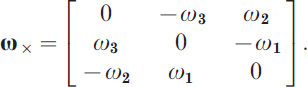
Then ΩG is defined as ΩG=ωG×. Similarly Ωb is defined as Ωb=ωb× where ωb is the body angular velocity in the body fixed frame.
In principle, the scalar acceleration measurements may be expressed as,

where zi, is the direction of sensitivity of the i th accelerometer, ri the position vector of the accelerometer location in the body fixed frame, ω=ωb and  is the inertial acceleration of the origin of the body frame. With six accelerometers it is, in principle, possible to express,

where,

It follows that,

Defining the vectors di as,

equation 8 may be expressed as,
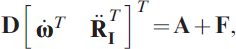
where,  ,
 , and
 .
Equation 12 may be expressed as,

At this stage it is important to recognise that the definition of the functions f i(zi, ri, ω), must be modified after considering that measurements of acceleration must be compensated by adding the local acceleration due to gravity. Furthermore the definition of the acceleration of gravity generally includes the centripetal acceleration due the earth's rotation rate vector, ωs. For this reason, one defines,

and the equations 13 may now be expressed as,

and the body components of the measured acceleration are,

where, G is the gravitational component of the acceleration in the body frame,  , b is a measurement bias vector and n is a measurement noise vector. It is possible to choose the location ri, and the direction of the measurements zi, such that, In equation 15:

Hence it follows that,

and

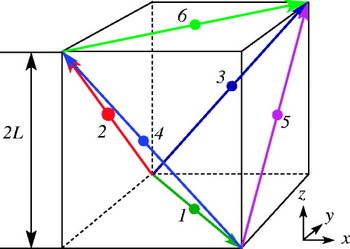
When the accelerometers are located on the faces of a rectangular cuboid, as shown in Figure 1, the vectors zi and ri may be expressed as,
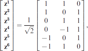

Equation 18 may now be integrated, in principle to obtain the body angular velocity vector, ω=ωb. The attitude quaternion is then computed from the equations,

where the quaternion is subject to the constraint qT⋅q=1. Once the solution for the quaternion is known, the transformation from the inertial to the body fixed frame Db,I is computed from,

and its inverse is obtained by same equation by changing the sign of q 4. The required transformation Dn,b may then be computed without matrix inversion from Dn,IDb,I−1, the transformations from the inertial to the n-frame and the inverse transformation from the inertial to the body fixed frame. Alternately Dn,b may be computed directly from the associated quaternion, representing the relative attitude of the navigation from relative to the body frame.
The GYROCUBE: A sensor for inertial measurements; the directions of the arrows indicates the direction of sensitivity of the accelerometers.

4. SATELLITE NAVIGATION MEASUREMENTS MODELLING
Pseudo-range observations are obtained by measuring the time taken for the signal to propagate from the satellite to the receiver and multiplying the measurement by the speed of light after it has been corrected for bias errors. Due to the lack of complete synchronization between the receiver and satellite clocks, errors in the orbital ephemeris, the delays due to the ionosphere and troposphere and multipath effects the measured pseudo-range is always biased. The pseudo-range measurement for a single satellite may be expressed in terms of the speed of light c, the satellite clock delay error dt, the receiver clock error delay dT, as,

where, ρm is the measured pseudo-range, ρ is the true magnitude of the pseudo-range vector, δρe is the pseudo-range error due to errors in the orbital ephemeris, δρion is the pseudo-range error due to delays in the ionosphere, δρtrop is the pseudo-range error due to delays in the troposphere, δρp is the pseudo-range error due to multi-path effects and v is the measurement noise. The errors due to errors in the orbital ephemeris, satellite and receiver clock biases, delays in the ionosphere, delays in the troposphere, and those due to multi-path effects may be estimated. Thus the estimate of the pseudo-range may be expressed in terms of the actual magnitude of the pseudo-range vector ρ, as,

The actual pseudo-range vector is related to the geodetic latitude λ, geocentric latitude λs, longitude φ and altitude h, by the relations,
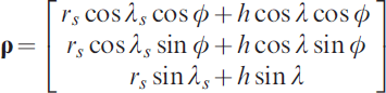
where ρ is the Earth centred, Earth fixed position vector of the body, r s the radius at a surface point of the flattened Earth ellipsoid and λs are defined in terms of the flattening f and the equatorial radius R e as:

and

To complement these pseudo-range measurements we assume that we also have independent measurements of the altitude and east geodetic longitude. This is necessary as the altitude and longitude kinematics have been included in the process model. Measurements of the altitude may be obtained from a radar altimeter while there are a variety of ways to obtain the east geodetic longitude. Alternately the longitude kinematics may be deleted from the process model.
5. RELATIVE POSITION AND VELOCITY ESTIMATION
Given the position coordinates of two points located on two independent bodies A and B respectively in space and the orientation of the two bodies in terms of the individual body attitude quaternion the relative orientation of body B with respect to body A can, in principle, be obtained by simply reversing the quaternion of body B followed by a composition with the quaternion of body A. However such computations are generally unreliable and so the orientation is estimated from estimates of the relative position and velocity of the two bodies. The relative position can be determined by determining the relative position in the reference coordinates and transforming it to the base coordinates in the body A. The velocity vector of body B relative to body A is determined by transforming the velocity components of body B to the same frame used to define the velocity vector of body A and subtracting from them the velocity components of body A. From the relative position and velocity estimates and measurements of the joint angles an UKF type mixing filter is implemented to estimate the joint angles and the true relative position of the end-effector in an ambulatory condition.
6. THE ADAPTIVE UNSCENTED KALMAN FILTER
Most dynamic models employed for the purposes of estimation or filtering of pseudo range errors or orbit ephemeris errors are not linear. To extend and overcome the limitations of linear models, a number of approaches such as the EKF have been proposed in the literature for nonlinear estimation using a variety of approaches. Unlike the Kalman filter, the EKF may diverge, if the consecutive linearizations are not a good approximation of the linear model over the entire uncertainty domain. Yet the EKF provides a simple and practical approach to dealing with essential non-linear dynamics. The main difficulty in applying the algorithm to problems related to the estimation of a spacecraft's orbit and attitude is in determining the proper Jacobian matrices. The UKF is a feasible alternative that has been proposed to overcome this difficulty, by Julier, and Uhlmann (Reference Julier and Uhlmann2000) as an effective way of applying the Kalman filter to nonlinear systems. It is based on the intuitive concept that it is easier to approximate a probability distribution than it is to approximate an arbitrary nonlinear function or transformation, of a random variable.
The UKF gets its name from the Unscented transformation, which is a method of calculating the mean and covariance of a random variable undergoing nonlinear transformation y=f(w). Although it is a derivative free approach, it does not really address the divergence problem. In essence the method constructs a set of sigma vectors and propagates them through the same non-linear function. The mean and covariance of the transformed vector are approximated as a weighted sum of the transformed sigma vectors and their covariance matrices.
Consider a random variable w with dimension L which is going through the nonlinear transformation, y=f(w). The initial conditions are that w has a mean  and a covariance Pww. To calculate the statistics of y, a matrix χ of 2L+1 sigma vectors is formed as outlined by Julier, and Uhlmann (Reference Julier and Uhlmann2000) . In this work the scaled unscented transformation is used as this transformation gives one the added flexibility of scaling the sigma points to ensure that the transformed covariance matrices are always positive definite.
Given a general discrete nonlinear dynamic system in the form:

where xk∊R n is the state vector, uk∊R r is the known input vector, yk∊R m is the output vector at time k. wk and vk are, respectively, the disturbance or process noise and sensor noise vectors, which are assumed to Gaussian white noise with zero mean. Furthermore Qk and Rk are assumed to be the covariance matrices of the process noise sequence, wk and the measurement noise sequence, vk respectively. The unscented transformations of the states are denoted as:

while the transformed covariance matrices and cross-covariance are respectively denoted as,

and

The UKF estimator can then be expressed in a compact form. The state time-update equation, the propagated covariance, the Kalman gain, the state estimate and the updated covariance are respectively given by,





Equations 32 are in the same form as the traditional Kalman filter and the extended Kalman filter. Thus higher order non-linear models capturing significant aspects of the dynamics may be employed to ensure that the Kalman filter algorithm can be implemented to effectively estimate the states in practice.
In order to employ the UKF when precise statistics of the process and measurement noise vectors are not available, the adaptive filter method proposed by Song, Qi and Han, Reference Song, Qi and Han2006 is used to estimate the orbit parameters. The covariance matrixes of measurement residuals are recursively updated in the UKF. The measurement noise covariance matrices, in the case of the UKF, may be expressed as:
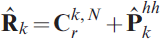
where, Crk,N is defined in terms of the sample size N and the residual rk as:

Equation 33 involves the further computation of  khh, by applying the unscented nonlinear transformation, hkUT(○k) to the state estimate, ○k. The measurement noise covariance may be updated in principle by employing equation 33. The nonlinear relationships between the covariance matrices also suggests that the update of Rk could be done by employing the covariance of the residual.
In the application considered in this paper, the adaptation of Qk implemented as it is, the process statistics are often unknown or may be considered to vary. It was observed that the magnitudes of the filter gains were relatively small and for this reason the exact expression for an estimate of Qk:

was approximated as:
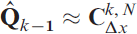
where CΔxk,N is defined as:

and

To update the process covariance matrix, Qk, the update law is assumed to be,

where the adaptation rate constant, αQ, is chosen to be a small number such as, αQ=0·01. It is also not required to update the process covariance matrix, Qk, after every integration time step. Thus the update of the process covariance matrix, Qk, is carried out only once every ten time steps, thus facilitating multi-rate adaptation.
7. APPLICATION TO A THREE LINK ROBOTIC LIMB
The reference frames and joint angles used to define the transformation of position and orientations, using the Denavit and Hartenberg convention, for a typical three-link robotic limb are shown in Figure 2. The link offsets and the link lengths are not shown on the same figure for clarity and are assumed to be h, d 1, d 2 and 0, a 1, a 2 respectively.
Reference frames and joint angles used to define the transformation of position and orientations for a typical three-link robotic limb.

The link offsets and the joint angles are estimates while the measurements of the joint angles are assumed to be available. The Denavit and Hartenberg transformations for relating the base frame to the end-effector frame are given by:
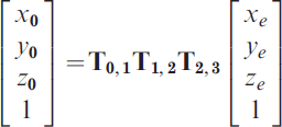

The velocity kinematics of the end-effector in the base coordinates may be expressed in terms of the joint angular velocity vector as;
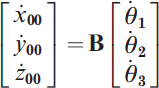
where,

Thus the joint angles may be expressed in terms of the translation velocities of the end-effector. In a practical situation, given noisy estimates of the relative velocities of the end-effector in the Cartesian base coordinates and noisy estimates of the end-effector relative position, the joint angular velocities may be estimated by solving a nonlinear filtering problem. Thus:

where 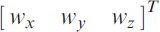 and
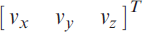 are vectors of independent white noise processes.
Equation 43 may be expressed as:

The joint angles are assumed to satisfy the bounds, −π<θ1<π,−π<θ2<π, −π<θ3<π. The matrix B is singular when the joint angle θ2=π/2. For this reason, when the joint angle θ2=π/2, the inverse of the matrix B is interpreted as the generalised inverse or pseudo inverse.
Given the position coordinates of the origin of reference frame at the end-effector, the link offsets and the link lengths, the joint angles may be computed in closed form. However, rather than use this closed form solution, a filtering problem is solved to obtain the true ambulatory position of the end effector. Thus it is assumed two satellite navigation aided inertial sensor packs are located at the origin of the base frame and at the origin of the end-effector. From the estimates of the position vector and velocity obtained from each location the joint angles and link offsets and biases may be estimated using a second independent UKF estimator to mix the position and velocity estimates at the two locations. Henceforth this second independent filter will be referred to as the inner filter while the two UKF estimators used to estimate the position and velocity at two locations are referred to as the outer filters.
In Figure 3 (Left) are shown comparisons of the relative position estimates produced by the outer filters, simulated and estimated end-effector relative position coordinates obtained by using the inner UKF based relative position estimator over a 6 second time frame corresponding to 30 000 uniform time steps. Initially the estimator seeks to track the simulated values but eventually tracks the outer filter estimates. Figure 3 (Right) shows comparisons of the corresponding simulated and estimated joint angle variations over the same time frame obtained by using three independent UKF based state estimators, without adaptation of the process covariance matrix, for the two satellite navigation aided accelerometer measurements and the robot kinematics position and velocity mixing. The figures indicate that the estimate is considerably noisy and that the filter tends to track the relative position estimates obtained by the outer filters in all three axes after about 20 seconds, rather than track the simulation. Thus the filter does not eliminate the drifts that may be present in the outer filter estimates.
(Left). Comparisons of the outer filter estimate, simulated and inner filter estimated end-effector position coordinates obtained by using UKF based state estimators over 30 000 time steps. (Right). Comparisons of the simulated and estimated joint angle variations over a 6 second time frame corresponding to 30 000 time steps.

In an attempt to reduce the noise in the estimate and improve the convergence of the outer filter estimate to the simulated relative position thus eliminating any drifts and biases that may be present, the adaptive UKF algorithm was used to estimate the positions and velocities at the two locations where the satellite navigation measurements are made, with the process covariance matrix updated recursively. Thus both the outer filters were configured to be adaptive while the inner mixing filter used to estimate the joint angles and link offsets continued to be non-adaptive. Figures 4 (Left) and (Right) illustrates the results obtained, with the process covariance matrices in the outer filters updated recursively, corresponding to Figures 3 (Left) and (Right) respectively. It can be easily observed that in the adaptive case, although the end-effector position estimated by the inner filter is substantially less noisy and that the estimate does latch on and track the true simulated relative position.
(Left) Comparisons of the outer filter estimate, simulated and inner filter estimated end-effector position coordinates obtained by using an adaptive UKF based position and velocity outer estimators over 30 000 time steps. (Right) Comparisons of the simulated and estimated joint angle variations corresponding to the adaptive UKF outer estimator over a 6 second time frame corresponding to 30 000 time steps.

The joint angles are now increased by a factor of three so they are all greater than π/2 over certain sections of the simulation time frame. The corresponding comparisons of the relative position estimates obtained from the outer filter estimates, simulated and estimated end-effector position coordinates obtained from the inner filter estimates are shown in Figure 5 (Left). In the outer filters the adaptive UKF estimator was used with the process covariance matrices updated recursively. The comparisons of the corresponding simulated and estimated joint angle variations over the same time frame are shown in Figure 5 (Right). The end-effector position coordinates continue to be estimated with almost the same accuracy as the case shown in Figure 4 (Left), although the joint angle estimates are relatively quite noisy.
(Left) Comparisons of the outer filter estimate, simulated and inner filter estimated end-effector position coordinates obtained by using an adaptive UKF based position and velocity outer estimators with the joint angles increased by a factor of three. (Right). Comparisons of the simulated and estimated joint angle variations corresponding to the adaptive UKF outer estimator, with the joint angles increased by a factor of three.

8. DISCUSSION AND CONCLUSIONS
In this paper the author has demonstrated the feasibility of implementing an adaptive unscented Kalman filter based mixing filter which may be used to estimate the relative position and orientations of prosthetic robotic limbs. The measurements were assumed to be made by six low cost ADXL203, type two axis accelerometers and a low cost altimeter. Measurements made by expensive sensors such as gyroscopes or high cost accelerometers, were assumed to be unavailable. The estimates of the relative position by using a standard UKF did not converge to the simulated relative position and the filters were unable to eliminate the drift in the position components. In an attempt to reduce the noise in the estimate and improve the convergence of the outer filter estimate to the simulated relative position thus eliminating any drifts and biases that may be present, the adaptive UKF algorithm was used to estimate the positions and velocities at the two locations where the satellite navigation measurements are made, with the process covariance matrix updated recursively. Thus both the outer filters were configured to be adaptive while the inner mixing filter used to estimate the joint angles and link offsets continued to be non-adaptive. When the adaptive UKF algorithm was used in the outer estimators there was substantial reduction in the errors in the estimated user position at the end of time frame while the filter itself converged to a steady state faster than the non-adaptive implementation. Thus the integrity of the ambulatory position estimated was maintained as the filter was able to eliminate all drifts and biases introduced by the outer filters. For this reason the adaptive filter was used to estimate the steady state ambulatory position of the end-effector after a disturbance or motion initiation. The steady-state ambulatory position error, in the relative position of the end-effector obtained from the outer filter estimates, is reduced by more than 98%. A major portion of the error in the relative position obtained from the outer filter estimates is a steady drift which is completely eliminated.