I. INTRODUCTION
In recent years, the interest in developing new energetic materials with biocidal capabilities Reference Chapman, Thompson, Ooi, Wooldridge, Cash and Hollins1,Reference Sullivan, Wu, Piekiel, Gaskell and Zachariah2 has drawn increased attention. Reference Schoenitz, Ward and Dreizin3–Reference Wang, Jian, Egan and Zachariah13 The motivation for this is based on evidence that conventional energetic materials, which employ a thermal neutralization mechanism, are not sufficiently efficient. Reference Sullivan, Pickiel, Chowdhury, Wu, Johnson and Zachariah14 Laboratory studies have demonstrated that the addition of a biocidal component can significantly enhance neutralization through a synergistic mechanism. Reference Zhou, Orr, Lee and Zachariah15–Reference Zhang, Badiola, Schoenitz and Dreizin20 Therefore, it has been proposed that simultaneously delivering a rapid thermal pulse with a remnant biocidal agent would prolong the exposure time and improve the inactivation process. Reference Wang, Jian, Zhou, DeLisio, Lee and Zachariah21 Both halogens and silver-containing energetic materials have been explored Reference Johnson and Higa22–Reference He, Zhang and Shreeve24 with the halogens offering the most promise due to their excellent biocidal properties. Reference Aly, Zhang, Schoenitz, Hoffmann, Dreizin, Yermakov, Indugula and Grinshpun25 Various methods have been used for incorporating halogens into energetic materials. One approach is through directly introducing halogens into the system and the other is by incorporating halogens into the oxidizers. Reference Aly, Zhang, Schoenitz, Hoffmann, Dreizin, Yermakov, Indugula and Grinshpun25,Reference Feng, Jian, Liu and Zachariah26 Thus, iodine-rich compounds that can release HI or I2 are the ideal candidates for biocidal energetics. Reference Fischer, Klapçtke and Stierstorfer27
Iodine (V) oxide, as one of the iodine-containing oxides with ∼76% iodine mass fraction, has been recently studied as an oxidizer with aluminum fuel. Reference Martirosyan28 In this case, various metals (primarily aluminum) are mixed with I2O5 to form a thermite system whose combustion properties were studied. Reference Little, Welle, Emery, Bogle, Ashley, Schrand and Lindsay29–Reference Jian, Chowdhury, Feng and Zachariah32 The first paper concerning the reactivity between aluminum and I2O5 was published by Ivanov et al. in 1980 in which a global reaction mechanism between iodine gas and fuels was proposed Reference Little, Welle, Emery, Bogle, Ashley, Schrand and Lindsay29 and confirmed in a later work. Reference Jian, Chowdhury, Feng and Zachariah32 I2O5 has received considerable interest because it is an extremely aggressive oxidizer with aluminum with reported propagation velocities up to ∼2000 m/s for loose ball-milled nano-aluminum and nano-scaled I2O5 (∼10 nm). Reference Martirosyan, Wang and Luss31 In addition, constant volume combustion tests on nano-Al/micro-I2O5 thermite exhibit the highest pressurization rate and the shortest burn time relative to other aluminum based traditional thermites such as Al/CuO and Al/Fe2O3. Reference Jian, Chowdhury, Feng and Zachariah32
Moreover, oxoacids of iodine, such as HIO3 and HI3O8, have been investigated in the recent decades. Until now, two polymorphs of iodic acid, the stable α-HIO3 Reference Stahl and Szafranski33,Reference Rogers and Helmholz34 and metastable γ-HIO3, Reference Fischer and Lindsjö35 have been reported and well-characterized. However, more evidence is required to verify the existence of β-HIO3. Reference Fischer and Lindsjö35 The thermal behavior of HIO3 was studied via thermogravimetric analysis/differential scanning calorimetry (TGA/DSC) and the result shows three decomposition steps upon heating in air: the dehydration of HIO3 into HI3O8 at 100 °C, the dehydration of HI3O8 into I2O5 at 210 °C, and the melting/decomposition of I2O5 at 400 °C. Reference Little, Emery, Nittinger, Fantasia and Lindsay36 It also reveals that I2O5 would be slowly converted to the initial hydrate HI3O8 and later to the final hydrate HIO3 under ambient environment. Furthermore, the crystal structure of HI3O8 was determined to be an adduct HIO3·I2O5, which are connected by hydrogen bonds. Reference Fischer37
Aerosol techniques offer a convenient route and potentially direct route for the preparation of nano-sized or micro-sized particles with high purity, and are a method proven to be amenable and economical to scale-up. Along with the fact that decreasing the size of oxidizer particles can improve the burn rate of thermite, Reference Jian, Chowdhury, Feng and Zachariah32 in this study we develop a synthesis approach to prepare various iodine oxide/iodic acid microparticles based on aerosol spray pyrolysis (ASP) using commercial iodic acid (HIO3) as the starting material, because of its water solubility and ready availability. Reference Sorensen, Li, Xu, Tang, Klabunde and Hadjipanayis38 The decomposition behavior of iodine oxides/iodic acids was also studied using low heating rates with TGA/DSC.
II. EXPERIMENTAL
A. Materials
Iodic acid (HIO3) (99.5 wt%) purchased from Sigma-Aldrich (St. Louis, Missouri) was directly used as received. All the other chemicals were of analytical grade and used as purchased without further treatment.
B. Preparation of various iodine oxide/iodic acid particles via aerosol spray pyrolysis
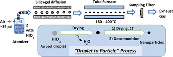
Small-sized particles of oxides were obtained via ASP. In general, 100 mL iodic acid aqueous solution (10 mg/mL) was sprayed into small droplets (∼1 μm in diameter) with a home-made pressure atomizer (∼35 pounds per square inch (psi) pressure air) and passed through a silica-gel diffusion drier (silica gels were regenerated at ∼50 °C or 80 °C to prepare different products) to remove water and are then passed through a tube furnace for chemical conversion. The tube reactor consisted of an ∼1.9 cm diameter alumina tube with a heated length of ∼40 cm. The furnace temperature was set at ∼230 and ∼375 °C to obtain either δ-HIO3 or I2O5, respectively, with a residence time of about 1 s. Reference Liu, Zachariah, Stoliarov and Li39 For both δ-HIO3 and I2O5, silica gels were regenerated at 50 °C. We find that δ-HIO3 can be obtained within a large range of temperature from 210 to 250 °C. In addition, HI3O8 was obtained with a tube furnace temperature ∼250 °C and silica gels regeneration temperature ∼80 °C. The final product was collected on a Millipore membrane filter (0.4 μm pore) and characterized by scanning electron microscopy (SEM; SU-70 FEG-SEM, Hitachi Corp., Tokyo, Japan) and powder X-ray diffraction (XRD; Bruker D8 Advance, Bruker Corporation, Billlerica, Massachusetts, using Cu Kα radiation).
C. In situ heating XRD measurement
In situ heating XRD was performed using a Bruker C2 diffractometer with a Vantec500 2D detector with 2θ ranging from 10° to 50° (λ = 1.5418 Å, step size = 0.05°) and the sample was heated via an Anton Paar DHS 1100 graphite-dome hot stage with a heating rate of 10 °C/min under air condition. We collected patterns at 26, 100, 200, 300, 400, and 500 °C and also collected a final pattern at 30 °C after the sample was cooled. At each temperature, we collected two 10 min frames at 20 and 40° 2θ. Integrating and merging the two frames together gave us a final powder diffraction pattern from 9.5° to 50° 2θ.
D. TGA/DSC measurement
TGA and DSC were conducted using a SDT Q600 (TA Instruments, New Castle, Delaware) equipped with a TA Discovery MKS104-S0212004 Micro Vision 2 mass spectrometer (TA Instruments). The analysis was performed under a 100 mL/min argon flow with ∼1.0 mg samples placed into an alumina pan and heated from room temperature up to 550 °C at a rate of 5 °C/min in argon atmosphere.
III. RESULT AND DISCUSSION
Iodic acid (HIO3) is a white solid at room temperature and is often used as the starting material for preparing iodine-containing materials due to its ready availability, high solubility in water, and that with controlled dehydration yields iodine oxides.
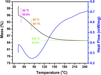
Atomized aqueous HIO3 droplets in air were passed through a silica gel diffusion dryer to produce solid HIO3 particles which were then directly passed through the tube furnace at a desired temperature to form various iodine oxide/iodic acids (Fig. 1). To determine what temperature should be run for the regeneration of silica gels, thermal analysis was conducted on a fully hydrated silica gel and the result is shown in Fig. 2. The black line represents the mass change of the silica gel with increasing temperature. From this, we note that the silica gel reaches its fully dehydrated state after 15% weight loss (water loss). Assuming a fully dehydrated silica gel has a weight of 85 mg, it could absorb 15 mg of water to reach its fully hydrated state (100 mg weight).
Aerosol spray pyrolysis to synthesize various iodine oxides/iodic acids.

The TGA and DSC curves of a fully hydrated silica gel under argon environment at a heating rate of 5 °C/min.

For silica gelm=85 mg regenerated at 50 and 80 °C, they could absorb 4.4 and 8 mg of water, respectively, to reach their fully hydrated state based on the TGA result in Fig. 2. Since silica gels obtained from different regeneration temperatures have different water-absorbing capabilities, silica-gels regeneration temperature also plays an important role in the aerosol route. In this work, regeneration temperatures of ∼50 and 80 °C were used to obtain different products to change the water absorbing properties.
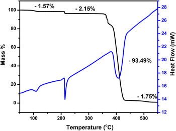
Since iodic acid droplets pass through the tube furnace where the thermal event occurs, we use TGA/DSC results to determine set points for the furnace. Figure 3 shows the TGA and DSC curves of iodic acid under air environment with a heating rate of 5 °C/min, which indicates that there are three decomposition steps: the dehydration of HIO3 to HI3O8 at ∼120 °C, dehydration of HI3O8 to I2O5 at ∼210 °C, and the decomposition of I2O5 at 380 °C. Thus, I2O5 and HI3O8 could be obtained via thermal treatment at 210–380 °C and 120–210 °C, respectively. The thermal behavior of HIO3 under argon was very similar to the air case and the detailed information is shown in Fig. S2.
TGA and DSC curves of HIO3 under air environment at a heating rate of 5 °C/min.

The residence time for a droplet in the aerosol reactor is about 1 s, which is obviously much shorter than that in the TGA ramp time. To obviate this effect we ran the furnace temperature higher than what the TGA would indicate to speed up the kinetics. To validate the phases indicted in the TGA, in situ hot-stage XRD was performed on the HIO3 powder at a heating rate of 10 °C/min from room temperature to 500 °C in air. From Table I, I2O5 and HI3O8 could be obtained at 300–400 °C and 200–300 °C, respectively. The XRD patterns of HIO3 at different temperatures are provided in Fig. S3.
The chemical composition of HIO3 during in situ heating XRD test at different temperatures in air.

A. Preparation of I2O5
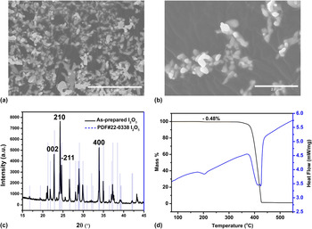
I2O5 [Fig. 4(c)] was obtained when the tube furnace was set at 350–400 °C which is consistent with the TGA result in Fig. S1. TGA and DSC curves of I2O5 [Fig. 4(d)] show the characteristically endothermic decomposition of I2O5 into I2 and O2 at ∼360 °C which also proves the formation of I2O5. The small weight loss at ∼210 °C indicates that small amount of I2O5 product is probably rehydrated into HI3O8 during the collection process and preparation for TGA/DSC test. The SEM images [Figs. 4(a) and 4(b)] show that I2O5 particles are irregularly spherical and some large aggregates are also observed in those images indicating that some sintering/coalescence between particles takes place.
SEM image (a and b), XRD pattern (c), TGA and DSC (Ar, 5 °C/min) (d) of as-prepared I2O5.

B. Preparation of δ-HIO3
Based on the thermal behavior of HIO3, HI3O8 could be obtained when the tube furnace was set at 120–210 °C. Considering the short residence time within the whole aerosol process and the difference between theoretical and experimental temperatures for preparing I2O5, the furnace temperature for the synthesis of HI3O8 was set higher at 210–250 °C.
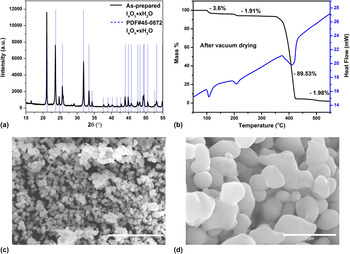
The XRD [Fig. 5(a)] spectra of the as-prepared iodine oxide were consistent with an XRD pattern previously identified as I4O9·xH2O (PDF#45-0872), with no indication of any other iodine oxide/iodic acid. Like I2O5 particles, the SEM images [Figs. 5(b) and 5(c)] show that “I4O9·xH2O” particles are irregularly spherical due to the sintering/coalescence between particles. This is also confirmed because the resulting particles are larger than expected based on the initial droplet size and concentration used and were nominally ∼400 nm in diameter.
XRD pattern (a), TGA/DSC (b), and SEM images (c and d) of as-prepared I4O9·xH2O after vacuum drying treatment.

The proposed structure implies that xH2O could be removed via vacuum drying. However, TGA/DSC and XRD results shown in Fig. S4 indicated surprisingly that there were no changes after vacuum drying. Moreover, the TGA and DSC results of I4O9·xH2O shown in Fig. S4 are very similar to those of HIO3 (Fig. S2), and this similar behavior was further confirmed with in situ heating XRD (Table II). Given that the previous report proposed the formula I4O9·xH2O without any chemical composition or any crystal structure information, Reference Wikjord, Taylor, Torgerson and Hachkowski40 we conjecture that the proposed formula may be in error.
The chemical composition of “I4O9·xH2O” during in situ heating XRD test at different temperatures in argon environment.

Based on its powder XRD pattern, we find a distorted octahedral crystal system, space group
 ${P_{{2_1}{2_1}{2_1}}}$
which consists of IO3 ions with three I–O bonds with distances of 1.78, 1.80, and 1.92 Å, and three I–O contacts with distances of 2.51, 2.76, and 2.76 Å. This reveals that the correct assignment of the phase is actually a previously unreported phase of HIO3, which we refer to as δ-HIO3. The detailed crystal information will be published separately. In addition, the difference between XRD patterns (Fig. S4) of as-prepared δ-HIO3 and as-received HIO3 also suggests a new phase HIO3.
Thus, instead of obtaining HI3O8, as the TGA results would suggest we obtain δ-HIO3 which indicates that the decomposition pathways of HIO3 in TGA (slow heating) and ASP (fast heating) are different. This result implies that the δ-HIO3 is metastable at elevated temperatures and at slow heating converts to I2O5. The ASP process enables a rapid thermal ramp and rapid quench to trap the material as δ-HIO3 which appears to be quite stable at room temperature. In fact, I2O5 was obtained when the furnace temperature was raised to above 300 °C.
C. Preparation of HI3O8
Based on the result in Fig. 3, we are expecting to obtain HI3O8 by thermal treatment of HIO3 at temperatures between 120 and 210 °C in air. Therefore, we annealed HIO3 at different temperatures in air for one hour and it turns out that HIO3 was fully dehydrated to HI3O8 at 150–260 °C (Fig. S5). Surprisingly, HI3O8 was obtained after only two minutes annealing at ∼165 °C (Fig. S5), which indicates that the dehydration of HIO3 is fast and also suggests that ASP is a promising method to prepare HI3O8.
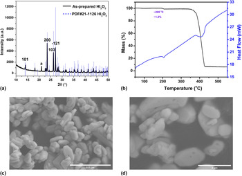
Previous results show that δ-HIO3 rather than HI3O8 is the product when the tube furnace was set between 210 and 250 °C with silica gels regenerated at ∼50 °C. Considering HI3O8 is a dehydrated product of HIO3, the failure to prepare HI3O8 might be caused by the relatively weak dehydrating capacity of the original setup. Again, I2O5 appeared when the tube furnace was increased to 300 °C or above. This suggested that tuning the tube furnace temperature alone could not obtain HI3O8. From the previous discussion, we know that the silica gel regeneration temperature also affects the aerosol synthesis and might be used to manipulate the hydrating ability of the setup. We found that regenerating the silica gel at ∼80 °C rather than ∼50 °C would form HI3O8 as confirmed by XRD [Fig. 6(a)] in a single step with a tube furnace temperature of ∼250 °C. The TGA shown in Fig. 6(b) indicates two decomposition steps: one is the dehydration of HI3O8 to I2O5 at ∼210 °C with an experimental weight loss of 1.2% (theoretical weight loss, 1.8%; impurities, ∼6%); another is the decomposition of I2O5 at ∼360 °C, both of which are endothermic as determined by DSC. Similar to δ-HIO3, the SEM images of HI3O8 in Figs. 6(c) and 6(d) show that particles are irregular spheres due to sintering/coalescence between particles during preparation.
XRD pattern (a), TGA/DSCa (b), and SEM images (c and d) of as-prepared HI3O8. (a: Ran under argon environment at a heating rate of 5 °C/min.)

IV. CONCLUSIONS
In summary three different products, δ-HIO3, HI3O8, and I2O5, were obtained via ASP as summarized in Table III. Both temperature and humidity control in silica gel preparation were necessary to obtain all three products without post-processing. For temperatures not listed in Table III, either mixtures (HIO3/HI3O8/I2O5) or no product was collected.
Summarizing the parameters of ASP for preparing different products.

This study demonstrates a facile and environment-friendly aerosol spray pyrolysis method to prepare various iodine oxides/iodic acids using a single precursor HIO3. By tuning the furnace temperature and the humidity, we were able to produce near phase pure δ-HIO3, HI3O8, and I2O5 as determined by XRD in a single step. TGA and DSC results show that HIO3 dehydrates to HI3O8, and then I2O5, and lastly I2O5 decomposes endothermically into I2 and O2.
Supplementary Material
To view supplementary material for this article, please visit https://doi.org/10.1557/jmr.2017.6.