I. INTRODUCTION
In the last decade, integrated mm-wave SiGe circuits found their way from research (e.g. [Reference Li, Rein, Suttorp and Böck1, Reference Pfeiffer, Reynolds and Floyd2]) to mass-market applications in automotive radar sensors (e.g. [Reference Forstner3, Reference Nicolson4, Reference Trotta5]).
For next generation radar sensors, it is important to further improve the performance of these circuits in order to reduce the costs and make them more reliable and more flexible for various sensors around a car.
It was the goal of the (radar on chip for cars) RoCC project funded by the German Federal Ministry of Education and Research to further improve radar sensors and their applications. This paper presents the project results of the circuit design work package of this project.
One of the focuses was to demonstrate on circuit level, what improvements can be achieved at 79 GHz due to the improved npn-transistor on technology level, which was a focused topic in another work package of this project. These circuit level results at 79 GHz are presented in Section II.
In Section III frequency doubler circuits exploiting radar transmitters at higher frequencies (around 150 GHz) are demonstrated. These circuits are based on Infineon's established B7HF200 production technology.
II. 79 GHz RADAR TRANSMITTER
One of the goals of the RoCC project was further improvement of the SiGe technology used for automotive radar circuits. The main focus of this development was the high-frequency performance of npn transistors. In addition to npn transistors, the process provides metal-insulator-metal (MIM) capacitors, different types of resistors, pnp transistors, and five layers of copper metallization.
The SiGe process developed within RoCC provides npn transistors with a maximum oscillation frequency f max of 380 GHz and a ring oscillator gate delay of 2.4 ps (see [Reference Chevalier6]). For applications in the 77 GHz/79 GHz bands, this allows for a significant reduction of the power dissipation of radar circuits. Sufficiently low power consumption is a prerequisite for the use of low-cost plastic packages.
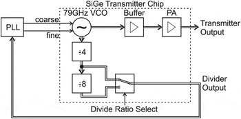
In order to evaluate the progress in circuit performance enabled by improved technology we have developed a 79 GHz radar transmitter. Figure 1 shows the block diagram of the circuit. It contains a voltage-controlled oscillator, a buffer stage followed by a power amplifier, and a frequency divider. This allows us to evaluate all of the key building blocks of a radar transmitter.
Block diagram of 79 GHz radar transmitter.

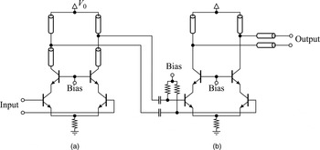
The voltage-controlled oscillator is based on a fundamental Colpitts oscillator similar to the circuit in [Reference Li, Rein, Suttorp and Böck1]. It uses two separate varactors for coarse and fine tuning to simplify frequency control using a phase-locked loop. The center frequency can be adjusted in discrete steps by laser fuses. The oscillator is followed by a buffer stage consisting of a differential cascode amplifier. The power amplifier, also based on a cascode stage, is shown in Fig. 2. Its input is AC coupled to the driver. The output matching network is realized with microstrip lines. They used the top metal layer (metal 5) above a ground plane on metal 3.
Schematic diagram of the 79 GHz buffer and power amplifier.

An integrated frequency divider allows the implementation of phase-locked loops for frequency control. The divider input is coupled to the oscillator and has to operate at frequencies exceeding 80 GHz. Therefore, the first frequency divider stage is realized as a regenerative divider because of its higher operating frequency and lower power consumption compared with static dividers. The following divider stages use conventional flip-flops. The divider output buffer contains a multiplexer that allows us to select a divide ratio of 4 or 32. The buffer provides a differential output signal and has on-chip 50 Ω termination resistors.
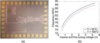
Figure 3(a) shows a chip photograph of the radar transmitter. The chip size of 1400×1100 μmReference Pfeiffer, Reynolds and Floyd2 is dominated by the pad frame. The active circuit requires only a small fraction of the total area.
79 GHz radar transmitter: (a) chip photograph and (b) measured tuning characteristics (coarse and fine tuning inputs connected in parallel).

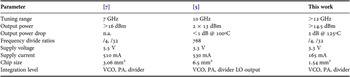
Figure 3(b) shows the tuning characteristics at T = 25°C and T = 100°C when coarse and fine tuning inputs are connected in parallel. The voltage-controlled oscillator achieves a tuning range larger than 12 GHz. The measured output power of the radar transmitter is higher than 14.5 dBm. Owing to the high gain provided by the npn transistors even at high temperatures, the output power drops by less than 1 dB between 25 and 100°C. The performance of the radar transmitter is summarized in Table 1.
Summary of radar transmitter data.

The excellent high-frequency performance of the transistors allows the circuit to operate with low power consumption. The supply current of the entire chip, including oscillator, buffer and power amplifiers, and the frequency divider is only 165 mA at a supply voltage of 3.3 V. This is a reduction of approximately 50% compared with similar building blocks in an earlier SiGe process generation [Reference Knapp7].
III. RADAR TRANSMITTER FOR f> 100 GHz
In order to evaluate the capabilities of radar transmitter circuits for higher frequencies above 100 GHz, we implemented two different frequency doubler circuits in Infineon's established production process B7HF200 (see e.g. [Reference Böck8]). It is a 0.35 μm SiGe bipolar technology with a minimum emitter width of 0.18 μm, both shallow and deep trench isolation, and four Cu metallization layers. Three resistor types, MIM capacitors, differential high-performance varactors [Reference Hung, Hancock and Rebeiz9], and Al-fuses are available. At optimum current density, the transistor cut-off frequencies are f T = 170 GHz and f max = 250 GHz, respectively.
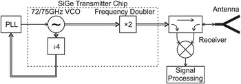
The block diagram of the radar transmitters is shown in Fig. 4. As fundamental oscillators do not work for signal generation up to the transit frequency, or to be precise, they show strongly degraded properties with respect to phase noise, output power, and tuning range. Therefore, the transmitters use a fundamental oscillator at half of the desired frequency followed by one of the two frequency doubler circuits.
Block diagram of radar transmitter for frequencies around 150 GHz based on a frequency doubler circuit fed directly by a VCO.

The oscillator is realized as a differential oscillator and is already presented in [Reference Pohl, Rein, Musch, Aufinger and Hausner10]. It delivers sufficient amplitude of ≈11 dBm for driving a frequency doubler. The additional frequency divider (÷4) for PLL-stabilization consists of two regenerative divider stages presented in [Reference Pohl, Klein, Aufinger and Rein11]. Finally, a coupler, a mixer, and an antenna can be added for wideband radar measurements similar to [Reference Pohl, Jaeschke and Aufinger12].
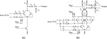
For evaluation of a frequency doubler, we implemented two different concepts (see Fig. 5). The first frequency doubler concept (DBL1, Fig. 5(a), cf. [Reference Hung, Hancock and Rebeiz9, Reference Bredendiek, Pohl, Aufinger and Bilgic13, Reference Öjefors, Heinemann and Pfeiffer14]) is based on a common emitter amplifier stage, where both collector nodes are connected together to sum up both current peaks of the distorted transistors T 3 resulting in a single-ended signal with a doubled frequency. The output signal is transformed by the lines L 6, L 7, L 8, and C 3 and given to the output pads.
(a) Schematic of the single-ended doubler (DBL1). (b) Schematic of the Gilbert-Cell doubler (DBL2).

As is well known, especially at mm-waves the use of differential circuit topologies results in many advantages. Therefore, we also implemented a fully differential frequency doubler based on a Gilbert-Cell mixer (DBL2, Fig. 5(b), cf. [Reference Forstner, Starzer, Haider, Wagner and Jahn15, Reference Bredendiek, Pohl, Aufinger and Bilgic16]). It has to be mentioned, that a Gilbert-Cell will only be fully differential, under simplified small signal conditions. Therefore, we added an additional common base stage (T 8) for better balanced output signals and reduced miller effect (cf. [Reference Bredendiek, Pohl, Aufinger and Bilgic16]).
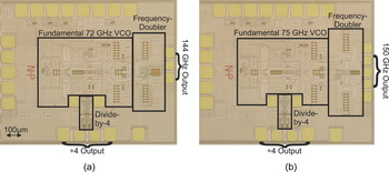
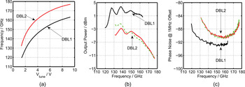
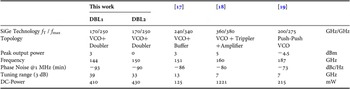
The chip photographs of both radar transmitters are shown in Fig. 6. The measurement results of both circuits are shown in Fig. 7. The tuning characteristics in Fig. 7(a) show slightly different center frequencies of 144 GHz (DBL1) and 150 GHz (DBL2), which were chosen for optimal performance of the dividers. Both tuning ranges are ≈45 GHz as expected from the used ultra-wide VCO (cf. [Reference Pohl, Rein, Musch, Aufinger and Hausner10]). The measured peak output power in Fig. 7(b) results in an excellent value of 3 dBm for the single-ended doubler (DBL1) and a lower, but quite well balanced, value of 2×−3 dBm = 0 dBm for the differential doubler (DBL2). A strong decay of the output power for higher frequencies may limit the usable frequency range (e.g. 130–160 GHz, below 3-dB variation) in practical applications. The measured phase noise at 1 MHz offset frequency (Fig. 7(c)) stays between −94 dBc/Hz and −84 dBc/Hz in the complete tuning range of both circuits.
(a) Photograph of the single-ended doubler chip (DBL1). (b) Photograph of the Gilbert-Cell doubler chip (DBL2).

(a) Measured oscillation frequency versus tuning voltage of the two doubler chips. (b) Measured output power versus frequency. (c) Measured phase noise versus frequency.

The performance of both radar transmitters is summarized in Table 2 and compared to previously published state-of-the-art signal sources in this frequency range. Both circuits confirm the feasibility of signal generation for ultra-wide band short range radar systems around 150 GHz even in an established production technology with a transit frequency of 170 GHz. Compared with the state-of-the-art, a very good performance is shown although all other implementations use faster technologies.
Summary of the 144/150 GHz radar transmitters compared with the state-of-the-art in modern SiGe technologies.

IV. CONCLUSION
The radar transmitter at 79 GHz clearly shows the advantage of using an improved technology. Owing to the use of a technology with an f max of 380 GHz, the power consumption of the circuit is reduced by about 50% compared to the production technology (f max = 250 GHz). This low power dissipation enables the use of plastic packages. Hence, a reduction in the overall assembly costs of the radar sensor can be obtained, which is mandatory to bring radar sensors in low-cost cars.
In addition, the potential of SiGe technologies for signal generation up to the transit frequency is shown with two different frequency doubler concepts. A single-ended frequency doubler achieves an output power of 3 dBm at 144 GHz, whereas a fully-differential Gilbert-Cell doubler achieves a slightly lower output power of 0 dBm (diff.), but enables the use of differential signals at these frequencies.
ACKNOWLEDGEMENTS
This work was supported by the German Federal Ministry of Education and Research within the project RoCC (FKZ 13N9822).
 Nils Pohl received his Dipl.-Ing. and Dr.-Ing. degrees from Ruhr-University Bochum in electrical engineering in 2005 and 2010, respectively. From 2006 to 2011, he was a Research Assistant with the Institute of Integrated Systems working on integrated circuits for mm-wave radar applications. In 2011, he became assistant professor for Integrated Systems at Ruhr-University Bochum. His main fields of research are concerned with the design and optimization of mm-wave integrated SiGe circuits and system concepts with frequencies up to 100 GHz and above (especially for wideband radar applications), as well as frequency synthesis and antennas. He is the author or coauthor of about 40 scientific papers and has issued several patents.
 Herbert Knapp Knapp received the Diploma and Ph.D. degrees in Electrical Engineering from Technical University Vienna, Austria, in 1997 and 2000, respectively. In 1993, he joined Siemens, Corporate Technology, in Munich, Germany, where he worked on circuits for wireless communications and high-speed data transmission. He is now with Infineon Technologies, Munich, Germany, and is engaged in the design of circuits for automotive radar applications.
 Christian Bredendiek was born in Gelsenkirchen, Germany, in 1981. He received the Dipl.-Ing. degree in electrical engineering at Ruhr-University Bochum in June 2008. Since August 2008, he has been a Research Assistant with the Institute of Integrated Systems, Ruhr-University Bochum. His current fields of research are frequency synthesis, working on system concepts, and integrated circuits for various mm-wave applications.
 Rudolf Lachner received the diploma and Ph.D. degrees in physics from Technical University Munich, Germany, in 1978 and 1984, respectively. He joined Infineon Technologies in 1984 where he was first engaged in process development and integration of high speed bipolar processes. Later on, he took over responsibility for the development of Infineons leading edge Silicon and Silicon-Germanium bipolar and BiCMOS processes. As a Senior Principal in the field of RF technologies, his main interests are currently in pushing the limits of SiGe technology into the Terahertz region and paving the way to broad usage of Si based mm-wave technology in new safety and communication applications. He has filed several patents and authored or co-authored many publications in this field.