I. INTRODUCTION
Sintering is a process for fusing particles together to provide enhanced electric, mechanical or other materials performance characteristics. It depends on diffusion of material to form physical connection points and several mechanisms can be important: lattice diffusion, viscous flow, grain boundary diffusion, etc.Reference German, Suri and Park1, Reference Chiang, Birnie and Kingery2 Reactive sintering is used in cases where composite structures are desired and are being developed to provide processing at lower temperature where the kinetics of the matrix particle might not be rapid enough to form the requisite interparticle connections on their own. One of the potential applications of such low-temperature reactive sintering processes is in developing titania anodes for dye-sensitized solar cells (DSSCs) that use flexible substrates (where the substrate would be sensitive to otherwise higher treatment temperatures). We and other groups have used alkoxide reactive chemistries to prepare titania anodes by this method.Reference Du Pasquier3–Reference Murali, Lee and Birnie5
Reactive sintering can also be used to build microstructures that are essentially parallel to structures that could come from sintering of previously synthesized core-shell particles. Multi-oxide materials with core-shell or composite structures have enormous scientific and technological value in materials science due to their unique and tailored properties.Reference Elder, Cot, Su, Heald, Tyryshkin, Bowman, Gao, Joly, Balmer, Kolwaite, Magrini and Blake6–Reference Jiaqi, Li and Chen9 Silica-titania mixed oxides, in particular, have received a lot of attention in recent years because of their applications in photocatalysis.Reference José, van Grieken, López-Muñoz and Marugán10–Reference Gaoand and Wachs12 Methods to prepare silica-titania oxides include impregnation, precipitation, reverse micelle suspension and sol–gel techniques.Reference Zhao, Yu and Cheng13 One of the simplest methods, of course, is impregnating the nominally inert silica supporting structure with a solution of titanium alkoxide or tetrachloride precursor.Reference Srinivasan, Datye, Hampden-Smith, Wachs, Deo, Jehng, Turek and Peden14–Reference Choi, Park and Singh16 We have adopted the silica-titania system for our model studies to examine how reactive liquids are situated in composites of this type, though we expect the findings to be applicable to the majority of reactive sintering systems.
Prior work in the field of silica-titania core-shell or composite oxides has been on oxide multilayers in which the silica particle framework of the composite structure helps deliver an increased surface area of titania; one of our earlier papers discusses this aspect and demonstrates the utility of these composites for DSSCs.Reference Murali, Lee and Birnie5 In the present study, we have performed a model 2-D experiment to look at the same kind of silica-titania structures. They have been deposited by spin coating to make thin layers with two-particle necks that are amenable to viewing with microscopy. We have synthesized silica-titania coatings using a reactive titanium alkoxide precursor and (nominally) 0.5-micrometer commercial silica particles.
Scanning electron microscopy (SEM) was used to look at the morphology of these layers for several alkoxide concentrations—thus providing several amounts of reactive material available for interparticle neck formation. Image analysis software has been used to measure the exact geometry of two-particle chains of silica-titania and quantify neck width for these configurations. Neck geometry calculations have also been performed to associate with the experimental measurements of neck radius. To the best of our knowledge, this is the first study of its kind that focuses on particle necking in oxide structures at the sub-close-packed layer level.
This article is organized as follows: Sec. II gives an introduction to the theory of liquid bridges that lead to the formation of interparticle necks; then we give our sample preparation and experimental observations and discussion; a short conclusion section summarizes how these apply to 3-D samples.
II. THEORETICAL BACKGROUND
When liquid is introduced between two spherical particles, it can lead to the development of a stable liquid bridge, which (usually) produces resultant attractive force between the two particles. This arises from the concave shape of the bulk of the liquid (the capillary force) and from the surface tension of the liquid acting on the two bodies.Reference Lian, Thornton and Adams17 The contact between the three phases, solid, liquid, and vapor, induces the onset of forces between these particles, which will depend on physical-chemical aspects like the wettability of the particles, the geometry of the meniscus as well as the particles’ sizes and the separation between them.Reference Megias-Alguacil and Gauckler18
Megias-Alguacil and GaucklerReference Megias-Alguacil and Gauckler18 have presented the conditions for the formation of these pendular liquid bridges between spherical bodies and calculated the liquid volume of the bridge for a given distance between particles (even when the two particles are not in contact) by definite integration of both the solid and liquid profiles. In the case of reactive sintering, the fluid precursor is introduced into the 3-D structure, and as the reaction proceeds any near-neighbor particle pair could develop such a pendular liquid bridge. Pendular bridges for wetting fluids result in a net attractive force applied to the two adjacent particles; so to the extent allowed by the surrounding microstructure this will pull two nearby particles closer and build direct particle-particle contact points. And, in cases where the chemical reaction is facilitated by the reaction of solvent from the mixture then there will be a reduction in the liquid content with reaction time, which will typically lead to gradual increase in the interparticle forces during the reactive sintering process. Our 2-D experiment has been designed with low particle concentration so they do have relatively complete freedom to move into these directly contacting arrangements; this has been observed experimentally in the silica-titania structures discussed below.
For comparison with the present experimental data we quickly summarize a simpler calculation, a limiting case of the work cited above, which closely matches the conditions we have achieved in our experiments. We assume two spherical matrix particles in contact and a second phase forming a neck between these two particles, a neck that would have formed as the alcohol/alkoxide solution is drying and reacting to form the titania neck-forming material. We were interested in finding out how big the neck should be, given a certain amount of added final second phase. First we calculate the volume of the ring of fluid at a two-particle contact. Then we apply it to the data we have gathered on 2-D structures and later extrapolate to the full 3-D microstructure.
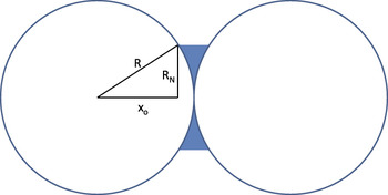
Figure 1 shows the geometry we have considered and identifies some of the variables that we use for this calculation. The sphere radius is R, the neck radius is RN, and xo is the x coordinate that defines one edge of the definite integral to be evaluated. First, we make a practical simplification of how the second phase will be shaped. Basically when capillary forces define the shape then we will expect the external second-phase will have curvature defined at the limits by a contact angle with the free solid sphere surface. This curvature can be either negative or positive and can then put the second phase under hydrostatic tension or compression. However, for the present purposes we are interested in cases where the second phase wets the particles well and the fraction is small, essentially where it will only be filling up a limited amount of the contact region and drawing the particles together. If we consider the range of shapes possible with small amounts of liquid then we see that the neck volume will not change substantially with different wetting- or external surface curvature. So, we make the simplifying shape assumption that the external surface is flat as in the cut shown before in Fig. 1. This enables the development of a relatively easy volume integral to find the neck volume. Basically, the volume of neck material is represented as a circular disk with two spherical divots taken out, one from each side. Using these assumptions we find that the neck volume and neck radius will be related in this way:

Two spheres in contact with a second phase forming a neck between them. The second phase is shaded.

For second phase fractions that are small in comparison to the sphere volume then we find that the neck volume will vary roughly as RN to the fourth power. In Sec. III, we will use experimentally obtained neck width information and compare them with this equation to describe the relation of neck volume to the neck radius.
III. EXPERIMENTAL PROCEDURE AND ANALYSIS
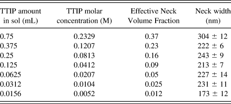
Titanium (IV) isopropoxide (TTIP), ethanol (ACS reagent, >99.5% assay) and 1-butanol (99.9%) were obtained from Sigma-Aldrich (St. Louis, MO) and used without further purification. Glacial acetic acid was purchased from ACROS Organics (Geel, Belgium). Silica powder (0.5 μm) was purchased from Alfa Aesar (Ward Hill, MA). The glass slides that were used as substrates were obtained from Fisher Scientific (Pittsburgh, PA). A sol of titanium isopropoxide (varying amounts, see Table I) was prepared using 0.625 mL acetic acid and 9.5 mL of 1-butanol. To this, 0.1 g of silica powder was added. After stirring for 30 min, the solution was spin-coated* Specialty Coating Systems model P6700 onto 1 mm thick plain glass slides that were precleaned with ethanol. A few drops of the prepared solution (enough to fully wet the surface) were placed onto the microscope slide piece that was held in the coater’s vacuum chuck. The spin speed used was 3000 RPM for 40 s. The samples were then air-dried and further heat treated at 500 °C for 30 min to form completely crystallized titania from the alkoxide precursor. After heat treatment the slides were coated with a thin layer of iridium to make the samples conductive. The iridium coating was applied using a Gatan model 681 ion beam coater (Gatan, Pleasanton, CA); the Ir coating thickness was approximately 10 nm. Scanning electron microscope (GEMINI ZEISS FESEM, Carl Zeiss Miscroscopy, Thornwood, NJ) with an Everhart-Thornley detector was used to study morphology of the sub-close-packed single layer structures. Image analysis was performed on the SEM images using ImageJ† (ImageJ version 1.42q; National Institutes of Health, USA).
Neck width measured as a function of reactive liquid concentration.
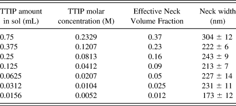
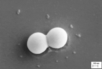
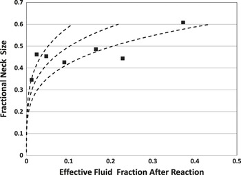
A representative SEM image (obtained at magnification of 150KX) is given in Fig. 2 and clearly shows the neck formed by the reactive precursor. The average neck width and the length of pairs of silica-titania structures were measured using ImageJ software. For each titania precursor concentration studied, four different particle pairs were measured and the average neck width was determined. As a self-consistency check, we also measured the long-axis dimension of the particle pairs. The results of image analysis are tabulated in Table I (raw data) and shown graphically in Fig. 3 for the fractional neck size of the particle pair neck regions (ratio of neck radius to silica particle radius) plotted as a function of second-phase (“liquid”) fraction after reaction (assuming full reaction of the alkoxide precursor to TiO2, but scaled down by the 30% surface coverage of silica particles in 2-D, as related to their sub-close-packed coverage).
SEM image (magnification=150 KX) of a silica particle pair with a titania coating for a precursor concentration of 0.0625mL TTIP.

Experimental data overlaid with expected behavior from theoretical analysis. Error bars associated with image analysis are smaller than the symbols used.

From the data in Table I, it can be seen that the neck width decreases by more than 40% as we reduce the titania precursor amount in the solution from 0.75 to 0.0156 mL, a 48-fold reduction in concentration. This means that by decreasing the titania precursor amount by a factor of almost 98% the neck width has decreased by only 43%—indicating preferential collection of titania at the neck regions. It also shows that in the context of interparticle connections in the titania anode of a DSSC, even very small amounts of titania precursor can provide significant particle-to-particle contact at the neck regions.
IV. DISCUSSION
The model developed above can now be used to analyze the experimental data. In addition to the data, Fig. 3 shows an overlay of dashed lines that come from the theoretical model. The centerline is plotted directly from Eq. (1). The other two lines have been added by doubling or halving the X scale. This might be necessary because of the large area of glass substrate that is coated by titania precursors but without having silica particles in all regions. This functional shape compares favorably with the general behavior that we found experimentally: for larger concentrations the response is relatively flat, but for small concentrations the neck radius rises quickly. In fact, performing dimensional analysis on Eq. (1) above we find that the neck radius varies roughly as the fluid volume fraction to the 1/4th power. This may seem surprising at first, but as the fluid quantity increases it is added to a wider and wider span around the ring at the edge of the neck, so the neck grows more slowly for each incremental addition of fluid.
While the general shape is consistent with the theoretical predictions, our data show that the neck size reaches a plateau that is quite a bit flatter than even the 1/4th power that we noted above. It is likely that this has resulted from conditions where the coating on the surface of the substrate is interacting with the coating material that is forming the neck: essentially the neck may be shedding fluid during the drying process and only keeping an amount consistent with the point when the fluid pinches off and becomes a distinct pendular bridge between the two neighboring particles. As such, it should be recognized that the experimental data are somewhat different from a simple two particle contact by itself: they are derived from pairs of particles sitting on a substrate where the substrate is also being coated with the neck-forming-material, and the neck forming material (the TTIP) is also covering the surfaces of the silica spheres as well. The experimental data showed that this surface coverage also increases when larger amounts of TTIP are added to the coating formulation (as indicated by somewhat greater observed two-particle long-axis-length data for larger TTIP concentrations). Given these variations in geometry, we believe that our data points match closely with the theoretical expectations.
At some point, the SEM resolution sets the limitation to the neck sizes we can measure because two silica particles adjacent to each other (but without any neck-forming-material) might still give the appearance of a neck simply because of the SEM imaging conditions and the image-analysis thresholds that must be selected. We did examine the neck region for particles deposited in the same manner, but without the addition of neck-forming precursors. Based on this standard examination in SEM then we believe for the lowest TTIP concentration we have chosen we are very close to the limits of measuring neck widths. Smaller concentrations would have been difficult to see for the imaging conditions found in our SEM and ImageJ analysis combination.
It is important to point out that we have purposely used very low concentrations of the titania precursor (TTIP) and silica particles to form sub-close-packed single layers; this was deliberate to enable observation of the interparticle necks that would form. As we move to higher concentrations of the TTIP, there would be excessive fluid that would create thicker layers on the substrate surface itself and also lead to cracking effects due to drying making it difficult to observe the necks closely.
The 2-D model experiment we have described can be used to obtain projections for a 3-D structure containing silica and titania as a composite. For a given porosity in the 3-D structure the number of interparticle necks can be estimated (using the relationship between the porosity and coordination number that is knownReference Van de Lagemaat, Benkstein and Frank19). Then using the neck width data the volume of titania in a neck and therefore the amount of TTIP needed to create that neck can be estimated [using Eq. (1)]. This calculation to obtain 3-D microstructure design is independent of the kind of host particle (only the host particle size is required). For example, we can apply the neck geometry calculations to our earlier work on silica-titania layers used as solar cell anodes.Reference Murali, Lee and Birnie5 Those coatings had a typical porosity of 65% with matrix particles being about 400 nm in diameter. Using the porosity-packing density relationship determined using computer modeling,Reference Van de Lagemaat, Benkstein and Frank19 the number of nearest neighbors to each silica particle and hence the number of interparticle necks can be estimated at about 4 per particle (for this packing density). Then applying Eq. (1) the total volume fraction of titania in the interparticle necks can be calculated; so with a neck diameter measured here in 2-D at 173 nm for the 400 nm silica source particles, the neck material comprises only 2.7% of the volume of the matrix particles. This geometry information can then be used to calculate the amount of the titanium alkoxide required to form the titania necks in the solar device coating. For the above geometry we require titanium isopropoxide in alcohol at approx 0.4 M/L. Since the coating formation step usually involves doctor-blade coating of a slurry then we would need this quantity of alkoxide to be contained in a solvent that would fill the remaining pore volume (though the solvent will evaporate during heating leaving the reactive materials at the neck contact regions, as we have seen).
Thus we need only very low amounts of the alkoxide precursor to connect porous structures together in 3-D, and this observation holds independent of host particle size. However, if there is a broader particle size distribution then smaller particles will have a capillary advantage pulling the reactive material into nanoporous regions or into the tinier necks between the smaller-sized fractions of the microstructure. This behavior was well explained by Shaw for general liquid distributions in liquid-phase sintering.Reference Shaw20 He determined that for small liquid contents then particle-particle contact regions would be the favored locations (as we desire in a reactive sintering process). However when more liquid is contained then the smaller pores will fill before large ones do, leading to an inhomogeneous microstructure. This is consistent with observations in our earlier paper where we noticed that silica particle morphology influences the performance of DSSCs; well-controlled spherical host particles were better than smaller irregular or porous particles for the host material.Reference Murali, Lee and Birnie5 Careful particle size distribution control will be critical for using reactive sintering for making DSSCs in the future. The measurements and calculations presented here demonstrate that relatively small amounts of reactive precursor are sufficient to create an interconnected structure that can provide reasonable performance in DSSCs.
V. CONCLUSIONS
We have performed model experiments aimed at understanding the interior composite neck formation process as it relates to reactive sintering, generally, and to low-temperature DSSCs in particular. We have found that only relative small amounts of reactive precursor (TTIP molar ratios as low as 0.0052) are necessary to form stable titania necks between silica particles. The novel approach of forming sub-close-packed single layers enabled us to directly examine the titania neck formation between pairs of silica particles by image analysis.
This approach can also be applied to a wide variety of mixed oxide and core-shell type of materials. The liquid-phase locations in these microstructures are very closely related to other liquid-phase arrangements found in composites, either by reactive sintering or liquid-phase sintering: there are similar surface tension effects driving microstructural changes; and, similar shrinkage and contact morphologies matter for many systems. This work is therefore a model examination of how neck widths vary as the precursor concentration is increased in a reaction-based sintering process between matrix particles.
ACKNOWLEDGMENTS
This work was supported by seed funding from the Rutgers University Academic Excellence Fund, the Malcolm G. McLaren Fellowship and by the NSF Ceramic, Composite, and Optical Materials Center (CCOMC) at Rutgers. We are thankful for experimental assistance provided by Tiffany Huang.