Introduction
Recently, the ultra-wideband (UWB) technology has been widely used in wireless communication and has attracted much attention in communication systems since the US Federal Communication Commission allocated the frequency band 3.1–10.6 GHz for commercial UWB systems [Reference Chu and Yang1]. As a critical part of the UWB system, the UWB antenna has received more attention due to its attractive characteristics such as low profile, wide impedance bandwidth, simple structure, nearly omni-directional radiation patterns, and easy integration with other compact UWB system circuits [Reference Chang and Kang2, Reference Ojaroudi, Ghobadi and Nourinia3].
It is necessary for a UWB system to be capable of rejecting interferences with other existing communication systems, including the worldwide interoperability for microwave access system (WiMAX) operating in 3.3–3.7 GHz [Reference Ryu and Kishk4–Reference Jiang and Che6], the local area networks (WLAN) for IEEE 802.11a which operates in 5.15–5.35 and 5.725–5.825 GHz bands [Reference Chang and Kang2, Reference Singh, Khanna and Singh7, Reference Cho, Kim, Choi, Lee and Park8], and the C-band IEEE INSAT/super-extended systems which operate in 6.7–7.1 GHz [Reference Ellis, Zhao, Wu, Nie and Liu9]. Therefore, UWB antennas with band-notched functions to reject the unwanted frequencies are desirable. Over the years, different techniques have been developed to realize the band-notching characteristics for UWB antennas. These include the etching square slots [Reference Ellis, Zhao, Wu, Nie and Liu9, Reference Mohammadi, Nourinia, Ghobadi and Majidzadeh10], U-shaped slots [Reference Cho, Kim, Choi, Lee and Park8], T-shaped slots [Reference Ojaroudi, Ojaroudi and Ghadimi11], C-shaped slots [Reference Chu and Yang1, Reference Trang, Lee and Park12], the split-ring resonator (SRR) [Reference Hong and Park13–Reference Ain and Chattoraj17], as well as rectangular strips [Reference Ryu and Kishk4, Reference Singh, Khanna and Singh7, Reference Azim, Mobashsher and Islam18, Reference Abdollahvand, Dadashzadeh and Mostafa19] and T-shaped strips [Reference Ojaroudi, Yazdanifard, Ojaroudi and Sadeghzadeh20]. However, the UWB antenna design with band-notched characteristics still faces many challenges, for example, to realize multiple band-notched characteristics in a limited radiating patch, and to control multiple band-notched frequencies for the different operating environment. Till now, most of the band-notched UWB antennas were designed with single [Reference Jiang and Che6, Reference Singh, Khanna and Singh7, Reference Hong and Park13, Reference Ojaroudi, Ghanbari, Ojaroudi and Ghobadi21–Reference Modak and Khan25], dual [Reference Chu and Yang1, Reference Ryu and Kishk4, Reference Jiang, Xu, Xu and Lin14, Reference Abdollahvand, Dadashzadeh and Mostafa19, Reference Abedian, Rahim, Danesh, Hakimi, Cheong and Jamaluddin26–Reference Mandal and Das28], or triple band-notched characteristics [Reference Trang, Lee and Park12, Reference Han, Chen, Han, Chen, Ma and Zhang15–Reference Ain and Chattoraj17, Reference Thakur, Jaglan and Gupta29]. Few had quad [Reference Wang and Gao30–Reference Modak and Khan33] or quintuple band-notched characteristics [Reference Xu, Shen, Zhang and Wu34–Reference Modak, Khan and Laskar38]. In addition, to avoid interferences with the WLAN systems, many UWB antennas were designed with a single notch covering 5–6 GHz [Reference Jiang and Che6, Reference Hong and Park13, Reference Han, Chen, Han, Chen, Ma and Zhang15, Reference Tang, Xiao, Deng, Wang, Guan, Wang and Ge16, Reference Azim, Mobashsher and Islam18, Reference Thomas and Sreenivasan22, Reference Ojaroudi and Ojaroudi24], which is wider than the WLAN operating frequency (5.15–5.35, 5.725–5.825 GHz). Having two separate notched bands is beneficial to improve the radiation efficiency.
In [Reference Wang and Gao30], a quad band-notching UWB antenna was proposed by inserting two SRR-shaped slots into the radiators and adding two parasitic meandered ground stubs close to the feed-line. The rejection bandwidth for WLAN is 0.6 GHz, which is too wide with respect to the 0.2 GHz requirement of the lower WLAN (5.15–5.35 GHz) and 0.1 GHz of higher WLAN (5.728–5.825 GHz). Another antenna in [Reference Sung31] was used as a modified H-shaped resonator beside the feeding line, but the bandwidths at the notch frequencies of lower and higher WLAN were about 0.15 and 0.5 GHz which were not very ideal. Additionally, it is hard to adjust the notching bandwidth by optimizing the modified H-shaped resonator. In [Reference Modak, Khan and Laskar32], a compact UWB monopole antenna with quad band-notched characteristics using triple U-shaped slot and EBG unit cell is presented. The proposed antenna has exhibited a broad impedance bandwidth (2.9–10.5 GHz) with quad band-notched frequency at 2.80 GHz, 3.37 GHz,WiMAX, 4.08 GHz C-band satellite downlink communication system, and 5.95 GHz C-band satellite uplink communication system, respectively. In [Reference Modak and Khan33], a quadruple notched UWB MIMO antenna is proposed. The proposed antenna exhibited a large functional bandwidth ranging from 3.0 to 10.7 GHz and the proposed antenna is suitable to reject four inquisitive frequencies (3.3, 4.03, 5.4, and 6.0 GHz, respectively).
In [Reference Xu, Shen, Zhang and Wu34], a portrait quintuple UWB antenna was designed using C-shaped slots, nested C-shaped slots, U-shaped slots, and open-circuit stubs. Similarly, in [Reference Mewara, Deegwal and Sharma35], a quintuple band-notched Y-shaped UWB antenna is achieved by placing three pairs of the C-shaped slot on the ground plane and designing inverted U-shaped slots on Y-shaped radiating patch. In [Reference Rahman and Park36], the authors designed a UWB antenna with quintuple rejection bands for IoT applications utilizing RSRR and RCSRR. In [Reference Modak, Khan and Laskar37], a planar monopole penta-notched UWB antenna is designed using EBG structures and modified U-shaped slots. In [Reference Modak, Khan and Laskar38], an UWB monopole antenna with penta-notched rejection characteristics using EBG structures and fork-shaped slots is proposed. The sizes of these antennas are 31.8 mm × 26 mm [Reference Xu, Shen, Zhang and Wu34], 38 mm × 36 mm [Reference Mewara, Deegwal and Sharma35], 30 mm × 28 mm [Reference Rahman and Park36], 31.3 mm × 34.9 mm [Reference Modak, Khan and Laskar37], and 31.3 mm × 34.9 mm [Reference Modak, Khan and Laskar38], respectively. All of these antennas are considered simple, with a small footprint and low cost, and thus a good candidate for future high-capacity UWB communication systems that are immune to abundant electromagnetic interferences. But the selectivity of the wide stop band is very poor. The wide notched-function with good selectivity is often needed to suppress some interference signals with a wide band (≥1 GHz) [Reference Xu, Shen, Zhang and Wu34, Reference Mewara, Deegwal and Sharma35]. The wide stop band of these referenced antennas [Reference Xu, Shen, Zhang and Wu34–Reference Modak, Khan and Laskar38] is generated by using only one resonator and cannot offer a sharp selectivity to meet the requirements of practical applications in most band-notched UWB antennas. The selectivity of the notched band is a crucial parameter in the band-notched UWB antenna design, which should be taken into consideration in the practical applications.
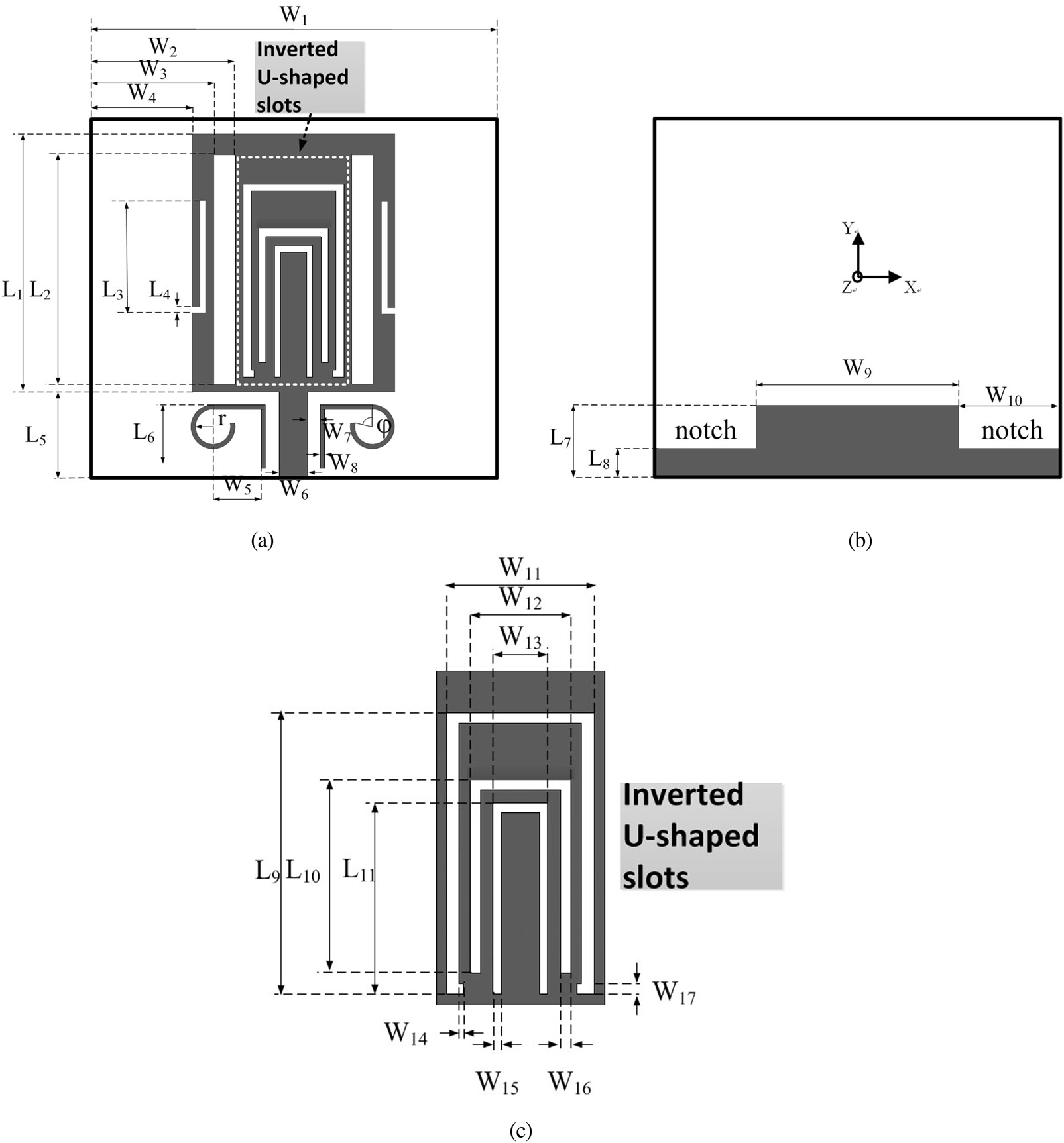
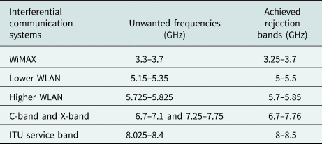
In this study, a new compact UWB antenna with quad and quintuple band-notched characteristics is studied. The size of the proposed antenna is 25 mm × 28 mm, which is smaller than the referenced antenna in [Reference Xu, Shen, Zhang and Wu34–Reference Modak, Khan and Laskar38]. Good quintuple band-notched functions are achieved at WiMAX (3.3–3.7 GHz), WLAN (5.15–5.35 and 5.725–5.825 GHz), C-band IEEE INSAT/super-extended (6.7–7.1 GHz) by using three modified inverted U-shaped slots and two symmetrical rectangular slots on the radiating path. Although wide stop bands have also been proposed in [Reference Xu, Shen, Zhang and Wu34–Reference Modak, Khan and Laskar38], the notched band is usually generated by using only one resonator and cannot offer a sharp selectivity to meet the requirements of practical applications in most band-notched UWB antennas. The selectivity of the notched band is a crucial parameter in the band-notched UWB antenna design, which should be taken into consideration in the practical applications. To obtain a high-selectivity wide stop band, the L-shaped slots and the rectangular slot are coupled together to shape a single stop band with two transmission poles. Furthermore, to reject the ITU service bands (8.025–8.4 GHz) and obtain quintuple band-notched characteristics, a pair of novel modified Rho-shaped resonators is also designed and discussed. All the notch frequency of the proposed antenna can be easily adjusted by changing the length and width of the slots on the radiating patch. Single, dual, and triple band-notched characteristics can also be easily designed by selecting the slots etched on the proposed antenna as can be seen in Fig. 1. Each notch frequency formed in the UWB antenna can be adjusted independently, and deep reflection zeros are formed between the adjacent notch frequency bands. The formation of reflection zeros improves the band-edge selectivity of the notch band, and the notch characteristic is more prominent. In addition, the wide notched-function with good selectivity is often needed to suppress some interference signals with wide band (≥1 GHz), which is also discussed in this paper. All the parameters of the slots and resonators are studied and optimized by the CST. Good reflection coefficient and radiation pattern characteristics are achieved in the frequency band of interest. The experimental results verify the design as a good candidate for UWB applications.
Geometry of the quintuple band-notched UWB antenna. (a) Top patch of the presented antenna; (b) bottom patch of the presented antenna; (c) geometry of the inverted U-shaped slots.

Antenna design
The final design of the UWB antenna with quintuple band-notched function is shown in Fig. 1. It consists of a rectangular radiating patch, a microstrip feeding line, and a notched ground plane. The notches on the ground plane are applied to optimize the electromagnetic coupling effects and improve the bandwidth of the monopole antenna.
The size of the proposed antenna is 28 mm × 25 mm. It is printed on an FR4 substrate with a thickness of 0.8 mm. The relative permittivity of the substrate is 2.65, and loss tangent is 0.036. Two rectangular slots (S1) and three inverted U-shaped slots (S2, S3, S4) are inserted into the radiating patch to realize quad band-notched characteristics.
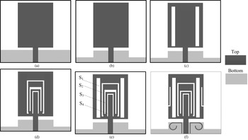
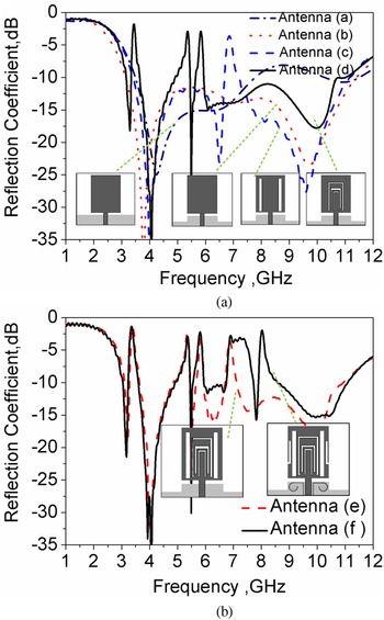
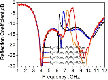
The evolution of the proposed band-notched antenna is shown in Fig. 2, and the corresponding reflection coefficient curves are compared in Fig. 3. Figure 2(a) shows the basic structure of the rectangle monopole antenna. It can be seen from Fig. 3(a) that the impedance of antenna (a) in Fig. 2(a) is not ideal at a high frequency (8–11 GHz), and does not meet the requirements of UWB antennas. In Fig. 2(b), two notches on the ground plane are applied to optimize the electromagnetic coupling effects and improve the bandwidth of the monopole antenna. It can be seen from Fig. 3(a) that after the ground plane is modified, the high-frequency reflection coefficient of antenna (b) has been significantly improved, and the −10 dB working bandwidth of antenna (b) is 3.1–11 GHz, which meets the requirements of UWB. In [Reference Ojaroudi, Ghobadi and Nourinia3], two rectangular slots on the radiating patch and a T-shaped notch on the ground plane are used to obtain broad bandwidth for the UWB antenna. In our study, we also find that the two rectangular slots on the radiating patch can also generate band-notched characteristics when we change the length of the two slots, as shown in Fig. 4. Therefore, in Fig. 2(c), two rectangular slots are designed on both sides of the antenna to suppress C-band interference, as seen in Fig. 3(a).
The evolution of the quad and quintuple band-notched antennas. (a) Monopole antenna without notched ground plane; (b) monopole antenna with notched ground plane, UWB characteristics, and without any notched bands; (c) UWB antenna with two rectangular slots; (d) UWB antenna with three inverted U-shaped slots; (e) UWB antenna with quad band-notched characteristics; (f) UWB antenna with quintuple band-notched characteristics.

Simulated reflection coefficient for the six antennas shown in Fig. 2.

The reflection coefficient of the antenna in Fig. 2(b) with a rectangular slot of different length.

In general, to obtain more notched bands, various slots can be added to the radiating patch, such as U-shaped, C-shaped, T-shaped, or SRR close to the feeding line. Here, as seen in Fig. 2(d), three inverted U-shaped slots are added to the radiating patch to form the other three notched bands, such as WiMAX, lower WLAN, and higher WLAN. Additionally, slots with a similar shape of the antenna can generate stronger resonance than any other shapes [Reference Han, Chen, Han, Chen, Ma and Zhang15]. It can be seen from Fig. 3(a) that, as described above, the antenna (d) has a good notch effect, and each stop band formed in the UWB antenna can be adjusted independently, and deep reflection zeros are formed between the adjacent stop bands. The formation of reflection zeros improves the band-edge selectivity of the stop band, and the notch characteristics are more prominent. Antenna (e) in Fig. 2(e) can be regarded as a combination of antenna (c) and antenna (d). Judging from the simulation results, the combined antenna (e) is getting more notches and has no negative impact on other frequency bands. The relationship between the notch frequency and the length of the slots are summarized by the following formula:

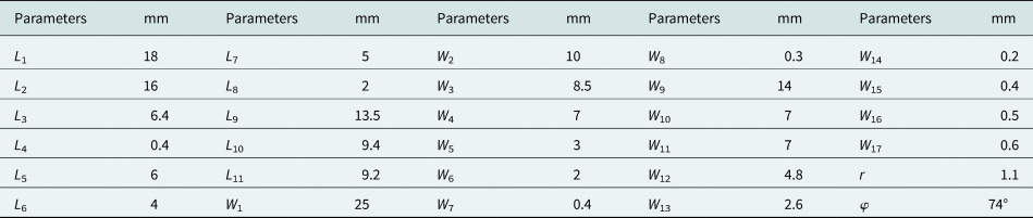
In this formula, f notch is the center frequency of notch band, L slot (in mm) is the total length of the slot and ɛeff ≈ (ɛr + 1)/2 is the effective dielectric constant. Based on (1), we can calculate the length of the slot at the very beginning of the design and then we can achieve quad band-notched antenna shown in Fig. 2(d). X-band as an interference frequency for the UWB systems is rejected in reference antenna [Reference Xu, Shen, Zhang and Wu34]. As we all know, C-band as an interference frequency for the UWB systems also needs to be rejected [Reference Cho, Kim, Choi, Lee and Park8]. Since the interference frequencies of C-band and X-band are adjacent, it is difficult to suppress them separately. One way to reject the two interference bands is to create a notched band with wide bandwidth, as seen in [Reference Xu, Shen, Zhang and Wu34–Reference Modak, Khan and Laskar38]. However, the notched band is usually generated by using only one resonator and cannot offer a sharp selectivity to meet the requirements of practical applications in most band-notched UWB antennas. The selectivity of the notched band is a crucial parameter in the band-notched UWB antenna design, which should be taken into consideration in the practical applications. So a wide high-selectivity notched band is formed by adding a pair of rectangular slots and a pair of symmetrical L-shaped slots. It is obvious in Fig. 3(b) that the bandwidth of the notched frequency is improved when the new slots are added near the rectangular slot S 1. Two notched bands could be produced by the use of two slot resonators. The two notched bands are coupled together to shape a single notched band with second-order characteristics, and two reflection zeros are generated at the sides of the notched band. As a result, a wide stop band with high selectivity is achieved. Furthermore, as can be seen in Fig. 2(f), a pair of novel Rho-shaped resonators is designed near the feeding line to achieve notched function at ITU service bands (8.025–8.4 GHz) and then a compact quintuple band-notched UWB antenna is obtained, as seen in Fig. 3(b). All the parameters of the proposed antenna have been optimized by using commercial full-wave software CST Microwave Studio (http://www.cst.com). The optimal dimensions of the presented band-notched UWB antenna are summarized in Table 1.
Final dimensions of the proposed design

Parametric study
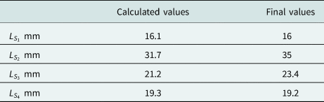
In order to avoid repeated discussion, we chose the quintuple band-notched UWB antenna as the object of studying the parametric. Table 2 illustrates the calculated values and optimal dimensions of the slots obtained from the CST simulation. It is found that there are slight differences between them. As shown in Fig. 1, the length of the rectangular slot S 1 is $L_{S_1} = L_2 = 16\,{\rm mm}$ , which is about half of the guide wavelength (0.49 λg), where the guide wavelength is $\lambda _g = \lambda /\sqrt {\varepsilon _{eff}}$
 . λ is the free space wavelength. The width of the slot S 1 is $W_{S_1} = W_3-W_2 = 1.5\,{\rm mm}$
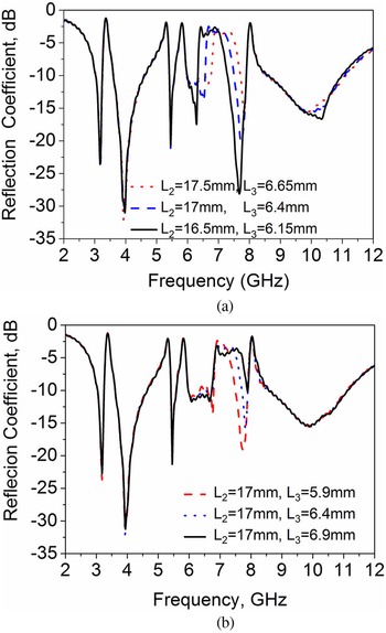
 . The wide bandwidth notched frequencies for C-band and X-band are generated by using the two rectangular slots and a pair of symmetrical L-shaped slots. So both slots are used for studies. Figure 5(a) shows the length of rectangular slots and L-shaped slots have an obvious influence on the center of the notch frequency. It is found that by decreasing the length of rectangular slots (by changing L 2) from 17.5 to 16.5 mm and decreasing the length of L-shaped slots (by changing L 3) from 6.65 to 6.15 mm, the notch frequency shifts toward the higher frequency clearly, and have slight effects on other notch frequencies. When the lengths of the rectangular slots are fixed, by changing the L-shaped slots, we can alter the bandwidth of the notch frequencies at C-band and X-band as seen in Fig. 5(b). In Fig. 5(b), it is observed that as the length of the L-shaped slots increased from 5.9 to 6.9 mm while fixing the rectangular slots length at 17 mm, the bandwidth of the notch frequency is changed from 6.8–7.5 GHz to 6.8–8 GHz.
The rectangular slot and L-shaped slot lengths on wide band-notched frequencies at C-band and X-band. (a) Changing L 2 and L 3, (b) fixing L 2 and changing L 3.

The calculated correlation factors of three configurations in different cases

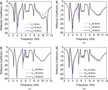
The effects of lengths and widths of three inverted U-shaped slots on the notched frequencies are also analyzed where only one parameter is changed each time, with the other parameters fixed, as shown in Fig. 6. Figures 6(a)–6(c) display that the length of the three inverted slots has a decisive influence on the center of the notched frequencies. It is found that by decreasing the lengths of three inverted U-shaped slots, respectively, the center of notch frequencies shifts to the higher frequency apparently. Figure 6(d) shows the effect of one of the inverted U-shaped slots. It is found that the thinner the width of U-shaped slots, the narrower the bandwidth of the notch frequency (WiMAX). Similarly, the notched frequency bandwidth of lower WLAN and higher WLAN can also be changed by changing the width of inverted U-shaped slots, respectively.
The inverted U-shaped slot length and width effect on notched frequencies. (a) The slot length effect on the center frequency of WiMAX band by changing L 9. (b) The slot length effect on the center frequency of lower WLAN band by changing L 10. (c)The slot length effect on the center frequency of higher WLAN band by changing L 11. (d) The slot width effect on the bandwidth of WiMAX band by changing W 15.

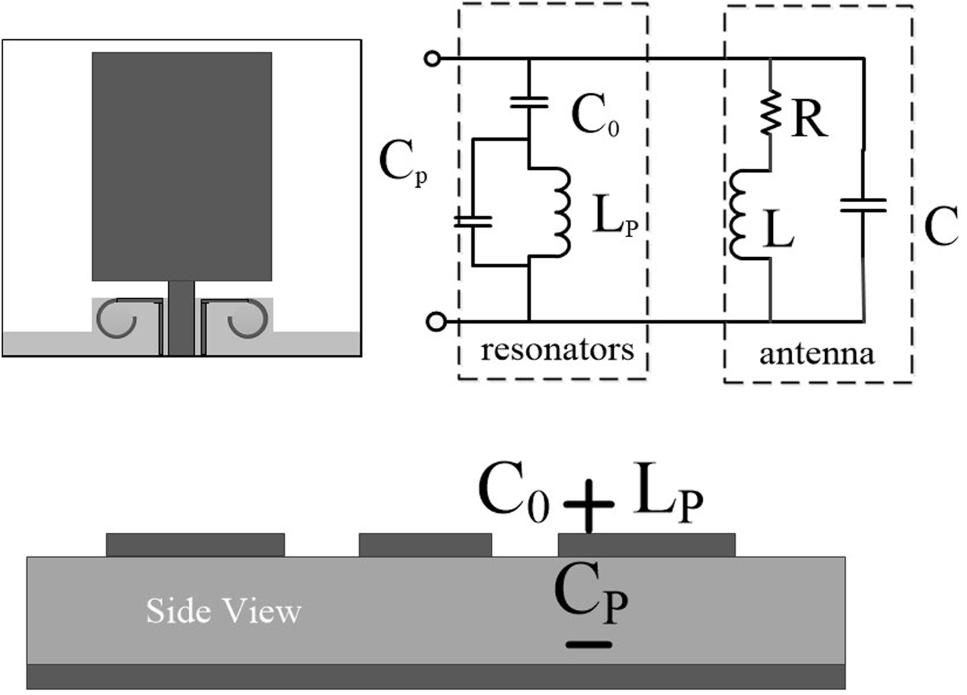
The fifth notch frequency is achieved by a pair of Rho-shaped resonators, as shown in Fig. 7. The main effects of the Rho-shaped resonators are its size and the distance from the feeding line. The equivalent-circuit model of the Rho-shaped resonator and the antenna is shown in Fig. 7. Therefore, the notch frequency generated by the Rho-shaped structure is obtained and can be calculated by $F_{Rho} = 1/\left({2\pi \sqrt {L_P( C_0 + C_P) } } \right)$ . The capacitance C 0 denotes coupling between the resonators and feeding line. The capacitance Cp is caused by the voltage gradients between the patch and ground plane, whereas the inductance Lp is generated by the current flowing through the Rho-shaped structure. In this design, the Rho-shaped structure can be referred as a half/one-wavelength resonator. To achieve the desired band-notched function, the band-notched frequency is given approximately by the expression


The equivalent-circuit model of the Rho- shaped resonator.

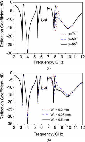
In this formula, fRho is the resonant frequency at 8.2 GHz, c is the speed of light in free space, LRho is the total length of the Rho-shaped structure, which can be calculated through (2) and ɛeff ≈ (ɛr + 1)/2 is the effective dielectric constant. The value of the inductor Lp mainly depends on the length of the Rho-shaped structure, so when the angle of the φ is changed, the corresponding inductance and resonant frequency will also change and the corresponding reflection coefficient with different φ is shown in Fig. 8(a). As can be seen from Fig. 8(a), the notched frequency is shifted from 8.3 to 7.9 GHz as the angle of the gap (φ) range from 74 to 86°. The effect of the Rho-shaped distance from the feeding line on the notch frequency (ITU service bands) is shown in Fig. 8(b). It is observed that as the Rho-shaped resonators are moved from the feeding line from 0.1 to 0.4 mm, the bandwidth of the ITU service bands is narrowed apparently.
The simulated return loss at ITU bands with different Rho-shaped size and distance from the feeding line. (a) Changing the size of Rho-shaped resonators by changing φ, (b) changing the distance from the feeding line by changing W 7.

Results and discussions
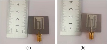
Both the quad and quintuple band-notched UWB antennas are manufactured and tested, and the photography of the two band-notched antennas is shown in Fig. 9. In this section, the numerical and experimental results of the quintuple band-notched antenna are discussed, including the return loss, radiation pattern characteristics, radiation efficiency, realized gain, and group delay. The optimum parameters of the presented antenna are determined by the commercial full-wave software CST Microwave Studio and the return loss of the presented antenna is measured by the Agilent E8363B vector network analyzer.
Photograph of the proposed antennas: (a) quad band-notched UWB antenna, (b) quintuple band-notched UWB antenna.

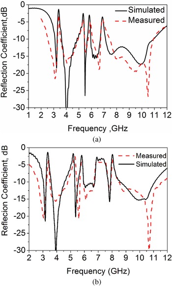
Figure 9 illustrates the measured and simulated return loss of the quad and quintuple band-notched antennas. As seen in Fig. 10, both the measured reflection coefficient of the quad and quintuple band-notched antennas <10 dB is from 2.6 to 11 GHz except for the notched-bands, which meets the requirements of the UWB system (3.1–10.6 GHz). Furthermore, the good agreement at the notch frequency is achieved between the simulated results and measured results, as shown in Table 3. The measurement results and the simulation results are in good agreement overall, but there are some deviations in the low-frequency cut-off frequency. The main reason for this phenomenon may be due to the connector and measurement errors. It can be seen that the presented quintuple band-notched UWB antenna has good performance at the five unwanted interference frequencies.
(a) The measured and simulated return loss of the quad band-notched antenna. (b) The measured and simulated return loss of the quintuple band-notched antenna.

Comparison of the achieved rejection bands and unwanted interference bands

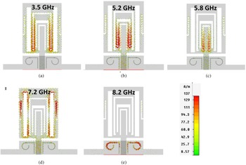
To better understand the effects of the slots and resonators behind the band-notched characteristics, the simulated surface current distributions on the radiating patch of the presented antenna at the notch frequency of 3.5, 5.2, 5.8, 7.2, and 8.2 GHz are presented in Fig. 11. It can be seen that there are strong current concentrated on the edges of the slots at notch frequencies 3.5, 5.2, 5.8, 7.2, and 8.2 GHz, respectively. Also, the currents in the other area of the radiating patch and ground plane are much weaker than those on the edges of the slots or the resonators. In this case, the power radiating performance and impedance are changed at the notch frequency.
Simulated surface current distributions on the radiating patch of the presented antenna at the notched frequencies.

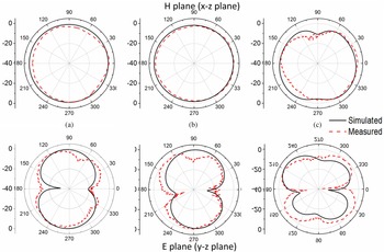
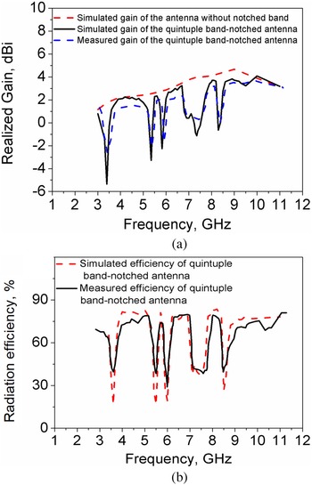
Figure 12 shows the measured and simulated radiation patterns of the presented UWB antenna at 4, 6, and 10 GHz, respectively. Good agreements are found in both the y-z plane (E-plane) and x-z plane (H-plane). An acceptable approximate omnidirectional radiation pattern is observed which meets the requirement for UWB systems to be able to receive signals from all directions. The measured gains of the presented antenna, simulated gains of the antenna without notched band, and simulated efficiency of the presented antenna are plotted in Fig. 13. It can be seen from Fig. 13 that the measured and simulated gain and radiation efficiency of antenna have relatively small errors. The reason for these errors may be due to the loss of the board or some connectors in the test. The maximum gain and radiation efficiency of this antenna are 4.5 dBi and 80%, respectively. It is observed that for passbands, the proposed antenna with and without notched band exhibits a nearly stable gain response with an average of 2.5 dBi. Sharp decreases of antenna gains and radiation efficiency in the desired notched frequency band at 3.5, 5.2, 5.8, 7.2, and 8.2 GHz are obtained. The experimental results verify the design as a good candidate for UWB applications.
The measured and simulated radiation patterns of the quintuple band-notched UWB antenna. (a) At 4 GHz, (b) at 6 GHz, (c) at 10 GHz.

(a) Measured and simulated gain of the quintuple band-notched UWB antenna. (b) Measured and simulated radiation efficiency of the quintuple band-notched UWB antenna.

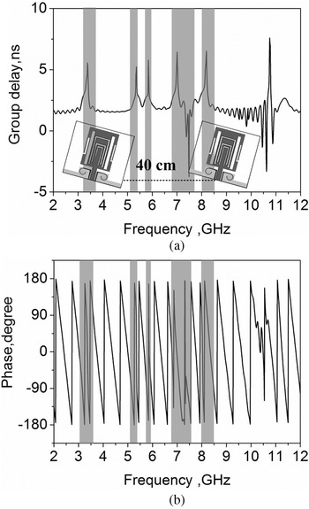
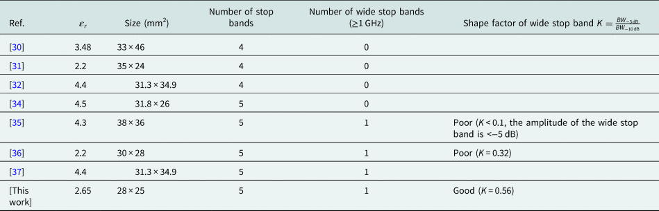
Having a constant group delay throughout the UWB band is another desired feature for a UWB antenna, dissatisfaction that may lead to strong dispersion resulting in pulse distortion. Figure 14(a) shows the simulated group delay of the presented antenna. To better understand the variation of the group delay, the phase curves of the two identical antennas are also given, as shown in Fig. 14(b). As can be seen, the variation of the group delay is <2 ns, except for the five notched frequencies. It can also be seen from Fig. 14(a) that the group delay has negative values at the frequencies 7.5 and 10.6 GHz. It can be seen from Fig. 14(b) that the change of phase in notch frequency band will be leading or lagging, and when the phase lead of phase, there will be negative value in the measurement of group delay. In addition, in the sideband of the operating bandwidth, the phase discontinuity also exists due to the impedance variation, which leads to a higher group delay in the 10.5 GHz. In Table 4, a comparison has been presented with the existing multiple band-notched characteristic antennas. It is clear from the table that the proposed quintuple band-notched antenna has the compact dimensions, and with good selectivity for wide stop band than the antennas reported in the references.
Phase responses and group delay for two quintuple band-notched UWB antennas. (a) Measured group delay of two identical antennas with quintuple band-notched characteristics. (b) Measured phase S 21 of two identical antennas with quintuple band-notched characteristics.

Comparison of competitive reference antennas performance

Conclusion
In this paper, a compact UWB antenna with quad and quintuple band-notched characteristics is designed and discussed. Also, the main characteristics of the proposed design are: (1) quintuple band-notched characteristic, (2) wide stop band with good band-edge selectivity, (3) compact size. Moreover, more detailed effects of all the slot lengths and widths about the quintuple band-notched antenna are investigated using commercial full-wave software CST Microwave Studio. Each notched frequency can be changed individually by changing the length or width of the slots. The simulated and measured results revealed that this design provides a convenient assessment for users to make a right choice when selecting the required antenna for specific applications.
Acknowledgement
This work was supported by the Natural Science Foundation of Shannxi Province, China (Grant No. 2021JQ-710, Grant No. 2021GY-049, Grant No. 2020GY-065) and in part by Xi'an Science and Technology Plan Project under Grant 2021JH-06-0038, 2020KJRC0102, 2020KJRC0102,2021-R-51. The State Administration of Science, Technology and Industry for National Defence Public Project: HTK2020KL504016. Scientific Research Program Funded by Shaanxi Provincial Education Department (Program No. 21JK0847)
 Hailong Yang received the B.S. degree in communicating engineering from Heze University, Heze, China, in 2012, and the M.S and Ph.D. degrees in communicating engineering from Xi'an University of Technology, Xi'an, China, in 2015 and 2019. He joined the Faculty of Electronic Engineering Department, Xi'an University of Posts & Telecommunications, in 2019. His research interests include wave propagation and antenna design.
 Jinsheng Zhang was born in 1980. He received the M.S. and Ph.D. degrees in control science and engineering from the Xi'an Research Institute of High-Tech, Xi'an, China, in 2005 and 2009. He is currently a professor at the Department of Navigation, Guidance and Simulation, Xi'an Research Institute of High-Tech, Xi'an, China. His recent research areas include flight vehicle guidance, control and simulation, and geomagnetic navigation.
 Xuping Li received the B.S., M.S., and Ph.D. degrees in electronic science and technology from Xidian University, Xi'an, China, in 2007, 2010, and 2018, respectively. From 2006 to 2018, he worked in the microwave engineering division of 206 Chinese weapons, where he was the director designer of antenna system, assistant minister and director of antenna room. He joined the Faculty of Electronic Engineering Department, Xi'an University of Posts & Telecommunications, in 2018. His research interests include phased array radar and antenna design.
 Yapeng Li received the B.S., M.S., and Ph.D. degrees in electronic science and technology from Xidian University, Xi'an, China, in 2013, 2016, and 2020, respectively. He joined the Faculty of Electronic Engineering Department, Xi'an University of Posts & Telecommunications, in 2018. His research interests include phased array radar and antenna design.
 Junhua Yang received the B.Eng. degree in electronic communication engineering from Sichuan Normal University, Chengdu, China, in 2008, the M.Eng. degree in signal and information processing engineering from the Chengdu University of Information Technology, Chengdu, China, in 2011, and the Ph.D. degree in information and communication engineering from the Northwestern Polytechnical University, Xi'an, China, in 2019. He is currently a lecturer with the School of Electronic Engineering, Xi'an University of Posts & Telecommunications. His current research interests include indoor localization, wireless communication, and machine learning.
 Xiaomin Shi received the B.S., M.S., and Ph.D. degrees from Xi'an University of Technology, Xi'an, China, in 2010, 2013, and 2017, respectively. She joined the Communication Engineering Department, Xi'an Shiyou University, Xi'an, in 2017. Her research interests include the analysis and design of microwave filters and RF passive circuits.