Introduction
Relating the macroscopic deformation behavior of a material to its microscopic defect processes is one of the key challenges of materials science. Transmission electron microscopy (TEM) has contributed continuously and extensively to this endeavor, starting with the investigation of crystal dislocations more than 60 years ago.Reference Hirsch, Horne and Whelan1 Already in these early days, first in situ mechanical testing stages were developed to observe dislocations at work under applied load.Reference Wilsdorf2,Reference Kear3 Since then, a large variety of sample holders and devices for in situ nanomechanical testing inside the TEM have been explored, ranging from classical in situ straining stages to nanoindentation holders and microelectromechanical systems-based actuators.Reference Yu, Legros and Minor4,Reference Dehm, Howe and Zweck5 Progress has also been made in the preparation of highly versatile samples for nanomechanical testing. In particular, modern focused ion beam (FIB) instruments enable site-specific preparation of samples with increased surface quality,Reference Oh, Legros, Kiener and Dehm6–Reference Mackovic, Przybilla, Dieker, Herre, Romeis, Stara, Schrenker, Peukert and Spiecker9 which can be further improved by post-treatments.Reference Kiener, Zhang, Šturm, Cazottes, Imrich, Kirchlechner and Dehm10,Reference Lee, Jeong, Kim, Han, Kiener and Oh11 Finally, TEM and scanning transmission electron microscopy (STEM) technologies have seen major developments in recent years with regard to resolution, stability, detection efficiency, and data processing, all of which are available for in situ mechanical testing studies.
The development of in situ TEM/STEM nanomechanics has been documented in a number of review articles.Reference Yu, Legros and Minor4,Reference Li, Wang, Mao and Wang12–Reference Dehm, Legros, Kiener and Dehm14 Here, we describe further progress by presenting selected recent work in which advanced in situ TEM/STEM studies have provided direct insights into fundamental deformation and defect processes in different classes of materials, ranging from metallic nanostructures to nanotwinned biological materials, from well-defined ceramic bicrystals to ultimately thin two-dimensional (2D) materials. Advanced in situ aspects range from atomic-resolution studies during mechanical straining, to highly controlled sample geometries and loading scenarios, to cyclic loading combined with environmental TEM, to micromechanical defect manipulation in low-voltage STEM.
Interplay of dislocation slip and surface diffusion
In nano-sized materials, the significant occurence of surfaces and interfaces as well as short diffusion lengths dramatically facilitate mass transport, thereby leading to fundamentally new deformation mechanisms.Reference Tian, Li, Sun, Ma and Shan15,Reference Guo, Wang and Li16 Recent advances in in situ high-resolution TEM (HRTEM) have successfully addressed the technical challenges for tracking atomic diffusion under loading, providing atomistic insights into diffusion-mediated deformation.Reference Sun, He, Lo, Xu, Bi, Sun, Zhang, Mao and Li17–Reference Liu, Wei, Song, Wang, Hirata, Fujita, Han, Zhang and Chen19
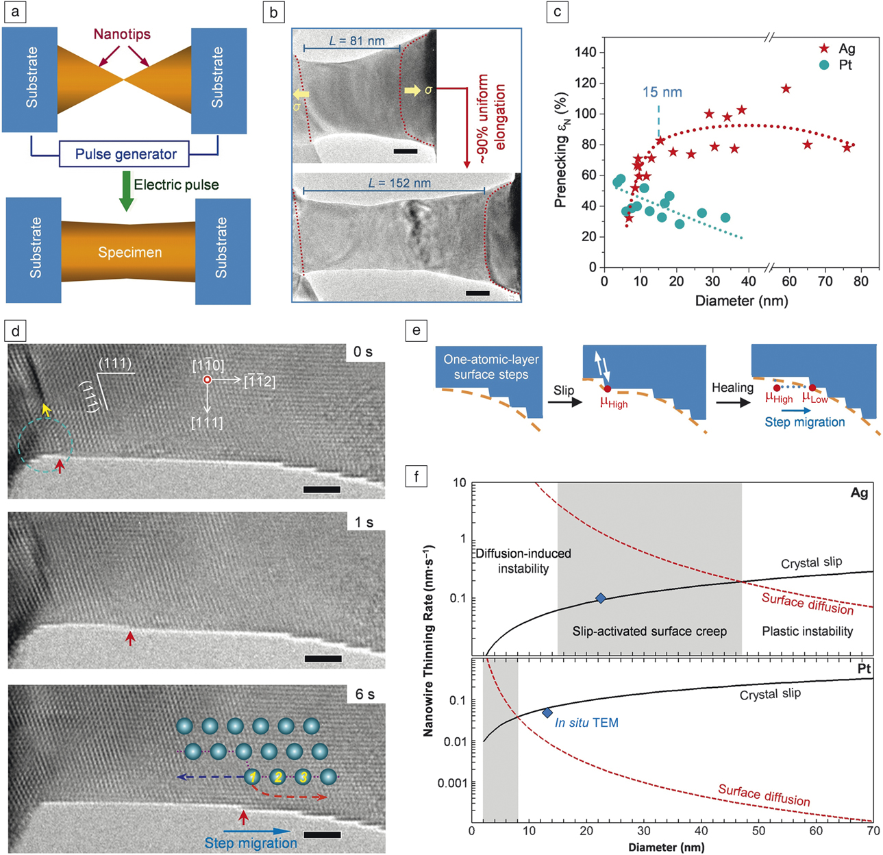
Zhong et al.Reference Zhong, Sansoz, He, Wang, Zhang and Mao18 recently discovered unusual superplastic behavior in single-crystalline Ag nanocrystals at room-temperature (Figure 1a–b), which is in stark contrast to the common plastic instability of defects-scarce metallic nanocrystals. The superplastic deformation results from an interplay between crystal slip and surface diffusion. As shown in Figure 1d, emission of one dislocation (yellow arrow) generates an atomic step (red arrow) that subsequently migrates toward faceted surface areas. This can be understood from the locally increased chemical potential associated with the step that activates surface diffusion to restore the low chemical potential in the smooth surface (Figure 1e), inducing a self-healing mechanism that redistributes the surface dislocation sources over the gauge length and eliminates the tendency for necking. The slip-activated surface creep regime varies significantly among metals with different surface diffusion energy barriers and homologous temperatures, resulting in profound differences in their mechanical behaviors (Figure 1c). These findings provide guidelines for simultaneously maximizing ductility and strength in nanoscale materials.
In situ high-resolution transmission electron microscope observation of slip-activated surface creep in metal nanocrystals.Reference Zhong, Sansoz, He, Wang, Zhang and Mao18 (a) Schematic of specimen preparation. (b) Superplastic behavior of Ag nanocrystal. Scale bar = 20 nm. (c) Normalized elongation before necking as a function of diameter of Ag and Pt nanocrystals. (d) Crystal slip and subsequent surface-diffusion-assisted migration of an atomic step. Scale bar = 2 nm. (e) Illustration of slip-activated surface creep. (f) Diameter-dependent thinning rates of plastically strained nanocrystals based on crystal slip and strain-dependent surface diffusion. Slip-activated surface creep (shaded area) occurs at different diameters for Ag and Pt explaining the different mechanical behaviors in (c). Note: TEM, transmission electron microscope. Note: μ, chemical potential in (e).

Nanotwin-governed toughening mechanism
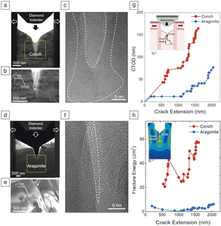
While nanotwinned metals have been extensively studied in recent years,Reference Li, Wang, Mao and Wang12,Reference Shan, Lu, Minor, Stach and Mao20–Reference Sun, He and Lu24 much less is known about the effects of nanotwins on the mechanical properties of ceramic materials. In the example presented here, advanced in situ TEM nanomechanics was combined with finite element modeling (FEM) to unravel the microscopic mechanism underlying the high fracture toughness of a conch shell composed of nanotwinned aragonite (CaCO3).Reference Shin, Yin, Li, Lee, Moon, Jeong, Kwon, Yoo, Kim, Zhang, Gao and Oh25 An in situ TEM technique has been developed that enables real-time observation of crack propagation and quantitative assessment of fracture toughness by measuring the crack tip opening displacement (CTOD). Using this technique, distinct differences between nanotwinned and single-crystalline aragonite have been observed (Figure 2). In nanotwinned aragonite (conch, Figure 2a–c), the main crack is temporarily arrested by multiple twin boundaries, accompanied by the nucleation of nanocracks ahead of the tip of the main crack.Reference Shin, Yin, Li, Lee, Moon, Jeong, Kwon, Yoo, Kim, Zhang, Gao and Oh25,Reference Li, Yin, Oh and Gao26 The crack tip appears blunt and is surrounded by amorphous (Figure 2c) and nanocrystalline phases, indicating considerable energy dissipation during crack propagation. In contrast, the main crack in single-crystalline aragonite remains sharp and propagates rapidly along the (110) cleavage plane (Figure 2d–f). Quantitative evaluation of the in situ data reveals a much increased CTOD for nanotwinned aragonite (conch, Figure 2g), corresponding to a one order of magnitude larger fracture energy compared to single-crystalline aragonite (Figure 2h), as calculated using FEM. These results demonstrate that preexisting growth twins play an essential role in enhancing the fracture toughness of brittle ceramic materials.Reference Li, Yin, Oh and Gao26
In situ transmission electron microscope (TEM) nanoscale toughness measurement revealing strongly increased fracture toughness of nanotwinned aragonite in Strumbus conch shell compared to single-crystalline aragonite.Reference Shin, Yin, Li, Lee, Moon, Jeong, Kwon, Yoo, Kim, Zhang, Gao and Oh25 (a–c) Indentation of a notched TEM sample of nanotwinned aragonite produces a serrated crack with a blunted crack tip surrounded by an amorphous phase (dashed white lines). (d–f) Same experiment in single-crystalline aragonite results in a straight crack with a sharp crack tip. (g) Crack tip opening displacement (CTOD) measured as a function of crack extension from in situ TEM data. (h) Fracture energy versus crack extension calculated using finite element modeling (inset).

Interaction of dislocations with grain boundaries
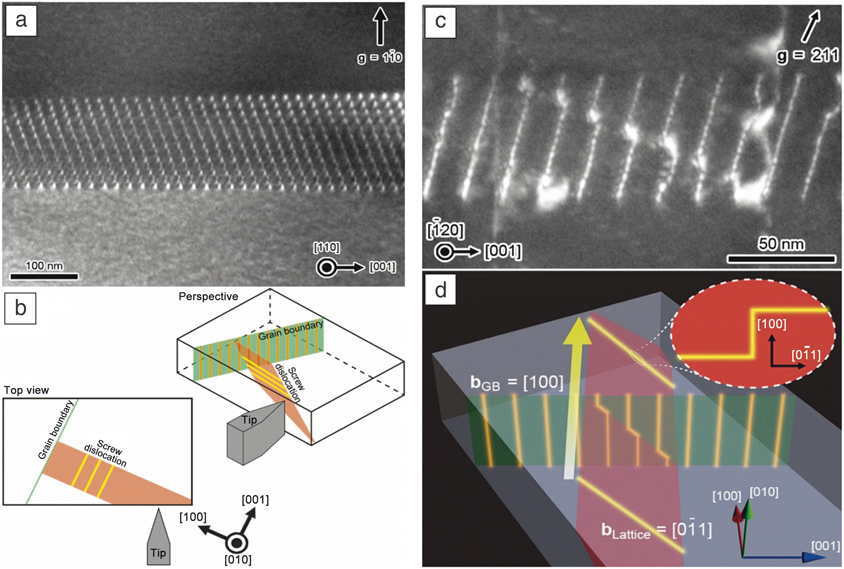
The deformation of polycrystalline materials crucially depends on the interaction of dislocations with grain boundaries (GBs). In situ TEM nanoindentation techniquesReference Ikuhara, Suzuki and Kubo27–Reference Kondo, Mitsuma, Shibata and Ikuhara30 provide unique opportunities to dynamically observe such interactions, including dislocation pileup and transmission. For example, a well-defined SrTiO3 bicrystal with low-angle tilt GB was employed as a model system to directly observe the interaction of moving lattice dislocations with GB dislocations.Reference Kondo, Mitsuma, Shibata and Ikuhara30 A TEM nanoindentation holder with double-tilt capability was used, which enables accurate orientation of the crystalline sample for optimized TEM contrast while the indentation is precisely controlled by a piezo-actuator. Figure 3a shows a dark-field (DF) TEM image of the initial GB with the specimen tilted to reveal the edge dislocation array on the GB plane. The geometric arrangement of the specimen, indenter and defects is illustrated in Figure 3b. During indentation, multiple screw dislocations are formed on a single slip plane and successively transmitted through the GB.Reference Kondo, Mitsuma, Shibata and Ikuhara30 Upon transmission, each dislocation intersection produces a kink in the moving screw dislocation and a jog in the intersected GB edge dislocation (Figure 3d). The jogs accumulate to “super jogs,” which can be directly observed (Figure 3c). The estimated super-jog length corresponds well to the product of the Burgers vector and the number of screw dislocations crossing the GB on the same glide plane. Such detailed insight into dislocation–GB interactions can only be obtained by advanced in situ TEM nanoindentation combined with detailed ex situ contrast analysis.
Interaction of screw dislocations with a low-angle tilt grain boundary (GB) in SrTiO3.Reference Kondo, Mitsuma, Shibata and Ikuhara30 (a) Dark-field transmission electron microscope (DF)-TEM image of initial GB, comprising an array of edge dislocations. (b) Geometric arrangement of specimen, indenter and defects. (c) DF-TEM image of the GB after in situ indentation revealing super jogs in the GB edge dislocations. (d) Schematic illustration of the process. Upon transmission of the GB by multiple screw dislocations, super jogs are formed in the GB edge dislocations, while kinks appear in the screw dislocations. Note: bGB, Burgers vector of grain boundary dislocation; bLattice, Burgers vector of lattice dislocation.

Dislocation locking by point defect complexes
Hydrogen embrittlement has been a major concern in industry for more than a century.Reference Johnson31 Still, the atomic mechanism by which hydrogen affects the mechanical behavior of metals remains controversial.Reference Cottrell and Bilby32–Reference Robertson34 Due to its high diffusivity, hydrogen is thought to be a weak inhibitor or even promoter of dislocation movement, which is supported by in situ TEM studiesReference Robertson35 and simulations.Reference Song and Curtin36,Reference Song and Curtin37
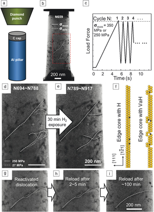
Xie et al.Reference Xie, Li, Li, Wang, Gumbsch, Sun, Ma, Li and Shan38 recently observed a different scenario (Figure 4) by careful design of a cyclic pillar compression experiment inside an environmental TEM (ETEM). Starting with an aluminum micropillar containing a few dislocations, cyclic loading with maximum stress of 350 MPa was programmed to directly compare the dislocation behavior with and without hydrogen. The experiment revealed that hydrogen can convert initially mobile dislocations into sessile dislocations under the same or even two times higher stress (Figure 4d–e). Upon degassing, the locked dislocations could be reactivated under cyclic loading to move in a stick-slip manner.Reference Xie, Li, Li, Wang, Gumbsch, Sun, Ma, Li and Shan38 However, relocking the dislocations required a much longer waiting time (∼103 s) than expected from hydrogen interstitial diffusion (Figure 4g–i). Atomistic simulations revealed that both the strong locking and slow relocking can be attributed to superabundant hydrogenated vacancies (HVs) (Figure 4f). HVs show much slower diffusion than interstitial hydrogen. Moreover, HVs change the core structure of an edge dislocation causing jogs, which require much higher shear stress to move. For metals with high vacancy concentration exposed to hydrogen, HVs could thus be a key plastic flow localization agent.
In situ observation of the pinning effect of hydrogenated vacancies on dislocation mobility.Reference Xie, Li, Li, Wang, Gumbsch, Sun, Ma, Li and Shan38 (a, b) Nanomechanical setup implemented in an environmental transmission electron microscope and aluminum pillar sample showing the observed area (dashed box). (c) Programmed cyclic compression. (d) Dislocation positions at peak and valley stress (solid/dashed lines) before hydrogen exposure. (e) All marked dislocations ceased motion after hydrogen charging. (f) Schematic showing edge dislocation with interstitial hydrogen (left) and hydrogenated vacancies (right). (g–i) A reactivated dislocation was recharged with hydrogen after a different waiting time, showing strong pinning after ∼100 min.

In situ manipulation of individual dislocations in 2D materials
Even though 2D materials are only one or a few atomic layers thick, they may contain dislocations.Reference Yazyev and Louie39–Reference Butz, Dolle, Niekiel, Weber, Waldmann, Weber, Meyer and Spiecker43 Among the various 2D materials, bilayer graphene is the thinnest material that can host dislocations with extended dislocation lines.Reference Alden, Tsen, Huang, Hovden, Brown, Park, Muller and McEuen42,Reference Butz, Dolle, Niekiel, Weber, Waldmann, Weber, Meyer and Spiecker43 Such basal dislocations are trapped between the two sheets of carbon atoms and cannot escape to the surface. Strain relaxation results in topographic ripples along the dislocation lines.Reference Butz, Dolle, Niekiel, Weber, Waldmann, Weber, Meyer and Spiecker43
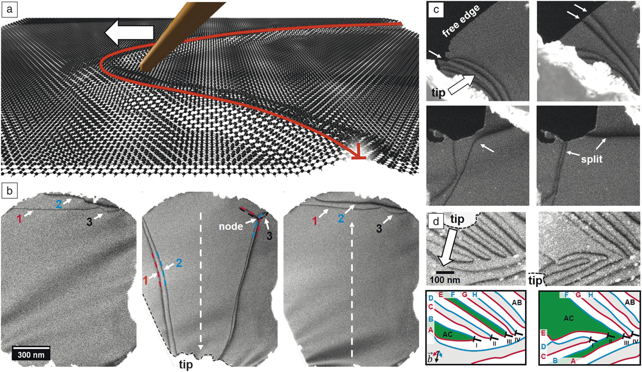
Schweizer et al. recently devised a method to directly manipulate individual dislocations in situ in bilayer graphene for the very first time by building upon the ultrathin nature of bilayer graphene and the unique properties of basal dislocations.Reference Schweizer, Dolle and Spiecker44 The method is based on a small tip mounted on a micromanipulator that can drag around dislocation lines inside an SEM (Figure 5a) while they are imaged using low-voltage STEM. In situ manipulation was used to study fundamental properties of dislocations, such as line tension and node formation (Figure 5b) as well as interaction with free edges (Figure 5c). Furthermore, a switching reaction was found, based on the recombination of dislocation lines. Upon dislocation reaction, the interconnectivity of bilayer areas with identical stacking order could be changed demonstrating a “topological switch” (Figure 5d).Reference Schweizer, Dolle and Spiecker44 Since basal dislocations act as barriers for charge transport in bilayer grapheneReference Kisslinger, Ott, Heide, Kampert, Butz, Spiecker, Shallcross and Weber45,Reference Shallcross, Sharma and Weber46 such switching reactions may be utilized as fundamental building blocks in future dislocation-based devices.
In situ dislocation manipulation in bilayer graphene.Reference Schweizer, Dolle and Spiecker44 (a) Artistic representation of the concept: a fine tip attached to a micro-manipulator can directly move around dislocations that are relaxed into topographic ripples. (b) Example showing the effect of line tension, which drives the dislocations back into their original state after manipulation. (1, 2, and 3 indicate the three partial dislocations with different Burgers vectors.) (c) Interaction of dislocations with free edges showing pinning at kinks and splitting of dislocation lines. (d) In situ manipulation can also be used to realize “topological switches,” where regions of identical stacking order (green) are interconnected or separated.

Challenges and future prospects
The previously discussed examples illustrate the versatility, by which advanced in situ nanomechanical experiments in TEM/STEM can provide new insights into deformation processes down to the atomic scale. Considering the extremely rapid development of TEM/STEM technology in the past 10–15 years, the exploration of state-of-the-art methodologies such as highly stable aberration-corrected TEM/STEM for in situ nanomechanics is still in its infancy. Liu et al.Reference Liu, Wei, Song, Wang, Hirata, Fujita, Han, Zhang and Chen19 recently used in situ aberration-corrected HRTEM in tandem with a direct detection camera to monitor the formation and migration of dislocation slip-induced surface steps during tensile testing of nanoporous gold. Making use of the strongly reduced contrast delocalization in aberration-corrected HRTEM, a first attempt was made to measure elastic strain at surface steps directly from in situ data in order to elucidate the interplay of strain, surface diffusion, and step migration.
In general, precise knowledge of local strain and stress states during in situ nanomechanical testing is highly desirable and key to quantitative understanding of defect processes, such as dislocation nucleation and propagation. In TEM/STEM experiments, this information can hardly be extracted from load-displacement curves because of delicate sample geometries and limitations in mechanical stability and force resolution. A promising alternative is the direct mapping of strain during in situ imaging. Here, we only mention nanobeam electron diffraction strain mapping (or four-dimensional STEM [4D-STEM], combining a 2D nanodiffraction pattern acquired at each point of a 2D scan area), which extracts strain from local diffraction patterns acquired at each probe position using a pixelated detector.Reference Müller, Ryll, Ordavo, Ihle, Strüder, Volz, Zweck, Soltau and Rosenauer47,Reference Ozdol, Gammer, Jin, Ercius, Ophus, Ciston and Minor48 Even though the technique is much slower than regular TEM or STEM imaging, time resolution can be improved using state-of-the-art direct detection camera technology.Reference Müller, Ryll, Ordavo, Ihle, Strüder, Volz, Zweck, Soltau and Rosenauer47–Reference Pekin, Gammer, Ciston, Ophus and Minor50 Pekin et al. recently demonstrated the possibilities of this multidimensional in situ imaging approach by mapping strain evolution during planar slip in stainless steel under in situ deformation.Reference Pekin, Gammer, Ciston, Ophus and Minor50
The direct dislocation manipulation demonstrated for bilayer graphene can be extended to other 2D materials such as few-layer MoS2 (or other transition metal dichalcogenides), which will provide new insights into fundamental defect processes in this emerging class of functional materials. Precise measurement of manipulation forces in conjunction with simulations may provide direct access to fundamental defect characteristics such as lattice friction (or Peierls’ potential) and stacking-fault energies. Finally, a combination of mechanical manipulation with other in situ techniques such as electrical probing is highly promising in understanding the functional properties of individual defects.
Conclusion
In summary, in situ nanomechanics in TEM/STEM provides unique opportunities for gaining deep insights into fundamental deformation and defect processes in materials down to the nanometer and atomic scales. Major progress has been made in the past years, as illustrated by the examples presented in this article. However, there remains a lot to explore and new technological advancements in the rapidly developing field of electron microscopy provide the perfect basis for major breakthroughs. Key prerequisites for future progress are expected to be advances in sample preparation and quality, improvements in mechanical force control and sensitivity, and full exploration of advanced TEM/STEM technologies, including direct detection cameras for improved time resolution and multidimensional in situ imaging.
Acknowledgments
E.S. acknowledges support from the German Science Foundation (DFG) through projects GRK 1896 “In situ microscopy with electrons, x-rays and scanning probes” and SFB 953, and thanks P. Schweizer for valuable discussions. S.H.O. acknowledges support from NRF of Korea through projects NRF-2015M3D1A1070672 and NRF-2018M3C1B7021994, and from ICT and Future Planning and Industrial Technology Innovation Program (10080654) of the Ministry of Trade, Industry & Energy (MOTIE, Republic of Korea). Y.I. acknowledges support from a Grant-in-Aid for Specially Promoted Research (17H06094) from JSPS, and ESISM from MEXT, and thanks S. Kondo, E. Tochigi, and N. Shibata for their collaboration. S.X. Mao acknowledges support from NSF CMMI 1760916 through the University of Pittsburgh. Z.W. Shan acknowledges support from the National Key Research and Development Program of China (No. 2017YFB0702001).

Erdmann Spiecker is a full professor of materials science and head of the Center for Nanoanalysis and Electron Microscopy at the University of Erlangen-Nürnberg, Germany. He received his PhD degree in physics from the University of Göttingen, Germany, in 1999. He has co-authored more than 230 publications on structural, functional and energy-related materials, including studies on 2D materials, nanoparticles and nanowires, thin films and heterostructures, solar-cell materials, porous structures, and high-temperature superalloys. His research interests focus on unravelling the relationship between formation, structure, and properties of materials using advanced methods of high-resolution, tomographic, analytical, and in situ electron microscopy. Spiecker can be reached by email at erdmann.spiecker@fau.de.

Sang Ho Oh is a professor at Sungkyunkwan University, Republic of Korea. He received his PhD degree in materials science and engineering from the Pohang University of Science and Technology, Republic of Korea, in 2002. He has co-authored more than 120 publications on topics such as the atomic and electronic structures of interfaces, deformation behavior of nanostructured materials, switching mechanisms of nonvolatile devices, and strain distribution in epitaxial heterostructures. His research focuses on in situ electron holography, negative Cs (spherical aberration coefficient) high-resolution transmission electron microscopy imaging, and scanning transmission electron microscopy imaging of surfaces and interfaces. Oh can be reached by email at sanghooh@skku.edu.

Zhi-Wei Shan is a professor at Xi’an Jiaotong University, China. He received his BS degree from Jilin University, China, his MS degree from the Institute of Metal Research CAS, China, and his PhD degree from the University of Pittsburgh. His research interests include the size effect on mechanical behavior of materials, hydrogen embrittlement, and magnesium-based advanced materials. His current research focuses on probing the properties and advancing the performance of materials from the nanoscale; developing technologies to enable the above goals, and accumulating and constructing the knowledge system of materials at the micro- and nanoscale. He also served as a volume organizer for the 2016 MRS Bulletin volume. Shan can be reached by email at zwshan@mail.xjtu.edu.cn.

Yuichi Ikuhara has been a professor and director of the Nanotechnology Center, Institute of Engineering Innovation, at The University of Tokyo, Japan, since 2003. He received his Dr Eng degree in materials science from Kyushu University, Japan, in 1988. He then joined the Japan Fine Ceramics Center. His current research interests include interface and grain-boundary phenomena, and advanced transmission electron microscopy. He has authored or co-authored approximately 750 original scientific papers, and received several awards, including the Medal with Purple Ribbon and the Humboldt Research Award. Ikuhara can be reached by email at ikuhara@sigma.t.u-tokyo.ac.jp.

Scott X. Mao is the William Kepler Whiteford Professor in the Department of Mechanical Engineering and Materials Science at the University of Pittsburgh. He obtained his PhD degree at Tohoku University, Japan. He completed postdoctoral research and was a visiting faculty member at the Massachusetts Institute of Technology and Harvard University. He was chair of the Mechanical Behavior of Materials Committee in The Minerals, Metals & Materials Society/ASM International. He has published more than 250 papers with an H-index of 55, and presented more than 100 invited talks in areas of deformation physics and fracture with in situ transmission electron microscopy. Currently, he is an editor of Advances in Metallurgical and Material Engineering and associate editor for Advances in Materials Research. Mao can be reached by email at sxm2@pitt.edu.