Introduction
Advances in materials have often been led by the development of new synthetic methods that provide control over size, morphology, and structure. The preparation of materials in a scalable and continuous manner is critical when development moves beyond lab-scale quantities. The ease and scalability for preparing materials have been a driving force for the development of new methodologies for several decades [Reference Hummel1].
In this respect, the development of aerosol syntheses has been particularly successful [Reference Kodas and Hampden-Smith2]. Spray pyrolysis (also known as droplet deposition) is defined as the aerosol process that atomizes a solution (by a nebulizer, e.g., pneumatic, ultrasonic, or electrostatic) and heats the droplets to produce solid products [Reference Che, Sakurai, Shinozaki and Mizutani3]. Spray pyrolysis involves the deposition of evaporating droplets containing reactants onto surfaces by a carrier gas, followed by further solvent evaporation and chemical reaction on the surface [Reference Kodas and Hampden-Smith2]. It is a simple, inexpensive, nonvacuum technique and one-step process with low waste production [Reference Liang, Felix, Glicksman and Ehrman4], and it has a relatively high deposition rate in a nonvacuum environment and can be easily scaled up to mass production [Reference Liu, Liu, Zhou, Zhao, Gao and Liang5]. Of the various nebulizer technologies, the use of ultrasonic nebulizers has been favored because of the narrow distribution and the small size of the produced droplets, has the advantage of being highly scalable and continuous [Reference Nandiyanto and Okuyama6, Reference Arya and Hintermann7], and is the one adapted in this work.
Since the pioneering work by Chamberlin and Skarman in 1966 [Reference Chamberlin and Skarman8] on cadmium sulfide films for solar cell applications, many studies used spray pyrolysis for the preparation of thin films of CdTe [Reference Nikale, Shinde, Bhosale and Rajpure9, Reference Gunjal, Khollam, Jadkar, Shripathi, Sathe, Shelke, Takwale and Mohite10, Reference Vamsi Krishna, Dutta and Koteswara Rao11, Reference Gunjal, Khollam, Udawant, Jadkar, Shelke, Sali and Mohite12, Reference Serreze, Lis, Squillante, Turcotte, Talbot and Entine13], noble metals, metal oxides, spinel oxides, and superconducting compounds [Reference Patil14]. Spray pyrolysis was used for the deposition of thin, thick, dense, and porous films as well as porous particles [Reference Kodas and Hampden-Smith2, Reference Pavlopoulos, Al-Khatiab, Button and Abell15, Reference Al-Khateeb, Pavlopoulos, Button and Abell16, Reference Al-Khateeb, Pavlopoulos, Button and Abell17, Reference Al Khateeb, Button and Abell18, Reference Zhang, Zhu and Virkar19, Reference Phua, Xu, Ma and Ong20, Reference Vergnières, Odier, Weiss, Bruzek and Saugrain21, Reference Paschos, Choi, Efstathiadis and Haldar22, Reference Skrabalak and Suslick23, Reference Suh, Jang, Suh and Suslick24, Reference Lee, Im, Lee and Seok25, Reference Bian, Li, Chen, Gao and Yu26]. It was also used for fine microstructure, powder, and nanoparticle production [Reference Phua, Xu, Ma and Ong20, Reference Perednis and Gauckler27, Reference Liu, Song, Tang, Zhang and Zhang28, Reference Jia, Xu, Ma, Prashanth, Yao and Wang29]. Additionally, colloidal spray pyrolysis was used for the production of powders and core anode–carbon shell structure for use as anode materials in lithium- and sodium-ion batteries [Reference Liang, Tian, Repac, Liou, Chen, Han, Wang and Ehrman30, Reference Tian, Liang, Repac, Zhang, Luo, Liou, Wang, Ehrman and Han31]. The crystallinity of materials produced by aerosol processes range from being single crystals [Reference Kodas and Hampden-Smith2, Reference Che, Sakurai, Shinozaki and Mizutani3, Reference Gurav, Kodas, Pluym and Xiong32] at one extreme to polycrystalline films exhibiting preferred orientation, or, at the other extreme, as completely amorphous films. The crystallinity, microstructure, preferred orientation of the film or powder, and particle size can be controlled through the processing conditions such as deposition (or reactor) temperature [Reference Al Khateeb, Button and Abell18, Reference Kang, Park, Lenggoro and Okuyama33], time history of the process, flow rate of the carrier gas, precursor concentration, precursor type, and the ratio of the pulse time to interval time [Reference Kodas and Hampden-Smith2, Reference Che, Sakurai, Shinozaki and Mizutani3, Reference Nikale, Shinde, Bhosale and Rajpure9, Reference Pavlopoulos, Al-Khatiab, Button and Abell15, Reference Paschos, Choi, Efstathiadis and Haldar22, Reference Bian, Li, Chen, Gao and Yu26, Reference Fu, Wu, Song, Song, Duo and Lin34, Reference Stryckmans, Segato and Duvigneaud35, Reference Wang, Qiao, Wang and Qian36, Reference Wang, Wang, Zuo and Qian37, Reference Wang, Wang, Liu, Zhang and Qian38, Reference Boone, Van Doren and Berry39] and by adjusting the deposition angle as in inclined substrate deposition (ISD) [Reference Al Khateeb40, Reference Pavlopoulos41].
In principle, a graded microstructure can be fabricated by ultrasonic spray pyrolysis because films with different porosity, microstructure, grain size, grain orientation, and possibly different composition and phase can be produced by ultrasonic spray pyrolysis. In other words, a multiple-step spray deposition consisting of changing the deposition processing conditions such as the precursor solution concentration, deposition temperature, solution flow rate, and others [Reference Hamedani42, Reference Gan-Moog Chow, Danny Xiao, Strutt, Strock, Zatorski and Kear43] could yield a functionally graded microstructure tailor-suited for a given application. The benefits of one such graded structure for lithium-ion battery (LIB) applications will be introduced later in this introduction and is the subject of this article.
In this work, iron pyrite (FeS2) thin films were deposited by spray pyrolysis as cathodes for LIB applications. The interest in FeS2 is due to its earth-abundance and low toxicity and because it is an inexpensive material that has long been of interest for electrochemical energy storage. FeS2 has recently gained attention as a high-capacity conversion cathode for rechargeable LIBs [Reference Al Khateeb and Sparks44]. It has a high theoretical capacity of 894 mA h/g and high theoretical energy density of 1313 W h/kg [Reference Li, Caban-Acevedo, Girard and Jin45, Reference Ghadbeigi, Harada, Lettiere and Sparks46, Reference Wadia, Alivisatos and Kammen47, Reference Cabana, Monconduit, Larcher and Palacín48, Reference Fong, Dahn and Jones49, Reference Zhu, Fan, Suo, Luo, Gao and Wang50, Reference Choi, Kim, Kim, Cho, Cho, Ahn, Ahn, Ryu and Gu51, Reference Evans, Piper, Kim, Han, Bhat, Oh and Lee52].
Because of the low cycling performance of FeS2, it has been synthesized in different forms to overcome this drawback. On the one hand, FeS2 in a powder and FeS2-carbon nanotubes forms have been prepared by different techniques as cathode materials for LIB applications. In such techniques, the synthesis process is either complex [Reference Zhu, Fan, Suo, Luo, Gao and Wang50, Reference Yersak, Macpherson, Kim, Le, Kang, Son, Kim, Trevey, Oh, Stoldt and Lee53, Reference Wen, Wei, Yang and Shen54, Reference Yoder, Tussing, Cloud and Yang55] or the utilized cathode electrode architecture requires the use of a conductive additive (such as modified carbon nanotubes), binder, and/or further processing procedures to be applied on the prepared FeS2 particles to fabricate the cathode electrode [Reference Li, Caban-Acevedo, Girard and Jin45, Reference Choi, Kim, Kim, Cho, Cho, Ahn, Ahn, Ryu and Gu51, Reference Evans, Piper, Kim, Han, Bhat, Oh and Lee52, Reference Yersak, Macpherson, Kim, Le, Kang, Son, Kim, Trevey, Oh, Stoldt and Lee53, Reference Wen, Wei, Yang and Shen54, Reference Yoder, Tussing, Cloud and Yang55, Reference Hu, Zhang, Zhu, Tao and Chen56, Reference Liu, Yuan, Qiu and Liu57, Reference Son, Yersak, Piper, Kim, Kang, Cho, Suh, Kim, Oh and Lee58, Reference Cheng, Wang, Lin, Li, Qiu, Zheng, Zhao and Zhang59, Reference Kapitanova, Mironovich, Melezhenko, Rokosovina, Ryzhenkova, Korneev, Shatalova, Xu, Napolskiy, Itkis and Krivchenko60]. The fabrication complexity and the use of nonelectrochemically active materials will limit the energy density of the cathode [Reference Evans, Piper, Kim, Han, Bhat, Oh and Lee52]. Hydrothermal, solvothermal, self-sacrificing, and other synthesis techniques were utilized in the literature for fabricating nongraded FeS2 thin film [Reference Al Khateeb and Sparks44, Reference Siyu, Xinyu, QingYu and Jun61, Reference Yufit, Freedman, Nathan, Burstein, Golodnitsky and Peled62] or slurry-coated [Reference Zhu, Fan, Suo, Luo, Gao and Wang50, Reference Choi, Kim, Kim, Cho, Cho, Ahn, Ahn, Ryu and Gu51, Reference Evans, Piper, Kim, Han, Bhat, Oh and Lee52, Reference Yersak, Macpherson, Kim, Le, Kang, Son, Kim, Trevey, Oh, Stoldt and Lee53, Reference Yoder, Tussing, Cloud and Yang55, Reference Hu, Zhang, Zhu, Tao and Chen56, Reference Liu, Yuan, Qiu and Liu57, Reference Son, Yersak, Piper, Kim, Kang, Cho, Suh, Kim, Oh and Lee58, Reference Cheng, Wang, Lin, Li, Qiu, Zheng, Zhao and Zhang59, Reference Chen, Wang, Wang, Wan, Liu and Qian63, Reference Liu, Wen, Wang, van Aken, Maier and Yu64, Reference Choi, Cheruvally, Ahn, Kim and Ahn65] cathodes.
Cathode films of various materials have been functionally graded in composition and/or microstructure using techniques other than spray pyrolysis and these have led to improved performance in fuel cells and batteries [Reference Hamedani42, Reference Xie, Navessin, Shi, Chow, Wang, Song, Andreaus, Eikerling, Liu and Holdcroft66, Reference Hart, Brandon, Day and Lapeña-Rey67, Reference Xia, Rauch, Wellborn and Liu68, Reference Liu, Compson and Liu69, Reference Liu, Guan and Liu70, Reference Wang, Eikerling, Song, Liu, Navessin, Xie and Holdcroft71]. However, other than our recent work [Reference Al Khateeb and Sparks44], no other reports were found on the spray pyrolysis deposition of FeS2 on metallic current collector for LIB applications. In our previous work [Reference Al Khateeb and Sparks44], porous thin films through the entire thickness were deposited by a vertical-up spray pyrolysis deposition setup. The deposited films were then sulfurized in sealed quartz ampules to crystallize FeS2. The utilized precursors were thiourea and ferric chloride, and the deposited films were free of binder and conductor. We established that nongraded FeS2 films deposited by spray pyrolysis performed better than the state-of-the-art FeS2 cathodes. Therefore, in this work we anticipate that functional grading of the pore structure will further enhance these cathodes. As before, we anticipate that the deposited films will operate without need of binder and conductor, which provides a further advantage because binder was found to degrade battery performance in the literature [Reference Inoue and Kawase72, Reference Younesi, Urbonaite, Björefors and Edström73].
Nongraded electrodes for LIBs
Vu et al. [Reference Vu, Qian and Stein74] stated that porous electrodes for LIBs lead to better cycle lives and high rate capabilities compared to nonporous electrodes. The pores facilitate the charge transfer across the electrode–electrolyte interface, reduce path length for ion diffusion, increase utilization of active material, and hence give larger specific capacity. They can also help in constraining expansion of active material during electrochemical cycling, thereby minimizing cracking of the electrode. It is also reported in the literature [Reference Liu and Liu75] that a more porous electrode provides more liquid phase for ion transport. Electrodes with low porosity provide less liquid phase for ion transport, which leads to less discharge specific power and less discharge specific energy in the cathode. Therefore, optimization of electrode design is a necessity. Researchers have investigated the different variables (thickness, structure, and porosity) of LIB electrodes because they relate to battery performance [Reference Inoue and Kawase72, Reference Younesi, Urbonaite, Björefors and Edström73, Reference Liu and Liu75, Reference Tiedemann and Newman76, Reference Newman77, Reference Srinivasan and Newman78, Reference Jiang, Qu, Zhou and Tao79, Reference Sikha, Popov and White80, Reference De, Northrop, Ramadesigan and Subramanian81, Reference Liu, Park, Lin, Sastry and Lu82, Reference Suthar, Northrop, Rife and Subramanian83, Reference Novák, Scheifele, Winter and Haas84]. It was found that reduction in particle size and optimizing the porosity and thickness of the positive electrode increased the power capability, the specific energy of the cell [Reference Srinivasan and Newman78], yielded larger discharge depths [Reference Jiang, Qu, Zhou and Tao79], and improved the conductivity (S/m) and diffusivity (m2/s) of lithium ions in the electrolyte [Reference Liu and Liu75, Reference Suthar, Northrop, Rife and Subramanian83].
It is also feasible to build an electrode around a porous current collector to improve the electrical contact between the current collector and the active material [Reference Vu, Qian and Stein74]. Zhang et al. reported large battery charge and discharge rates of MnO2 cathodes electrodeposited on a macroporous nickel current collector [Reference Zhang, Yu and Braun85]. The macroporous current collector, which provides rapid ion and electron transport pathways, was fabricated by electrodeposition using colloidal crystals of nickel. Therefore, in this work, FeS2 films will be deposited on aluminum microgrid current collectors to investigate the effect on battery performance.
Functionally graded electrodes
Electrodes graded in composition, structure, porosity, and grain size were fabricated by different techniques for fuel cells and LIBs applications as briefed below. Nevertheless, no reports were found on fabricating pore-graded structure of FeS2 cathodes for LIBs using spray pyrolysis technique or any other technique.
Graded electrodes for fuel cell applications
Improvement in fuel cell performance was achieved through electrodes graded in composition [Reference Xie, Navessin, Shi, Chow, Wang, Song, Andreaus, Eikerling, Liu and Holdcroft66, Reference Hart, Brandon, Day and Lapeña-Rey67, Reference Liu, Compson and Liu69, Reference Wang, Eikerling, Song, Liu, Navessin, Xie and Holdcroft71], microstructure [Reference Xia, Rauch, Wellborn and Liu68, Reference Liu, Compson and Liu69], porosity, and grain size. Slurry coating [Reference Xie, Navessin, Shi, Chow, Wang, Song, Andreaus, Eikerling, Liu and Holdcroft66, Reference Hart, Brandon, Day and Lapeña-Rey67, Reference Xia, Rauch, Wellborn and Liu68, Reference Wang, Eikerling, Song, Liu, Navessin, Xie and Holdcroft71], chemical vapor deposition [Reference Liu, Compson and Liu69], and spray pyrolysis were used to fabricate graded electrodes of different materials.
Spray pyrolysis
Hamedani et al. used spray pyrolysis to deposit pore-graded stronium doped lanthanum manganite (LSM) cathode on yttria stabilized zirconia (YSZ) electrolyte for fuel cell applications [Reference Hamedani42, Reference Hamedani, Dahmen, Li, Peydaye-Saheli, Garmestani and Khaleel86]. They produced a graded porous structure by applying a multiple-step spray in which the temperature and solution flow rate were changed. They obtained a fine layer close to the surface of the electrolyte and a coarser outer layer. In other words, large pores were formed facing the gas, which allowed for maximum mass transport into the electrode structure. Smaller pores and particles were made close to the electrolyte interface to create the maximum number of active reaction sites and to offer a large surface area for oxygen reduction.
The work we present in this contribution differs in three key ways to reports in the literature. First, there have been no reports of electrodes made by spray pyrolysis where the flow rate alone was used to provide the functional grading. Second, previous work, including the work by Hamedani et al. [Reference Hamedani42, Reference Hamedani, Dahmen, Li, Peydaye-Saheli, Garmestani and Khaleel86], relied on a 100 kHz ultrasonic atomizer, which will not produce fine particle sizes necessary for LIB applications [Reference Zhu, Fan, Suo, Luo, Gao and Wang50, Reference Wang, Robert, Chernova, Pereira, Omenya, Badway, Hua, Ruotolo, Zhang, Wu, Volkov, Su, Key, Whittingham, Grey, Amatucci, Zhu and Graetz87, Reference Ma and Garofalini88, Reference Al-khateeb, Lind, Santos-Ortiz, Shepherd and Jones89]. Third, the configuration for deposition of fine particles is vertical up in this work, which is necessary for the deposition of fine particles [Reference Mwakikunga90, Reference Ho Bang, Didenko, Helmich and Suslick91].
Graded electrodes for LIB applications
Few experimental or theoretical investigations of the LIB performance with graded electrode structure were found in the literature. LIB electrodes graded in porosity, thickness, and structure were obtained by slurry coating. However, graded FeS2 cathode for LIB applications are not reported in the literature.
Experimental investigation (slurry coating)
Liu et al. fabricated a porosity-graded LiNi0.5Mn1.5O4 (LNMO) LIB cathode by a lengthy (3+ days) and complex solid-state reaction process. This cathode structure was fabricated in an attempt to mitigate the degradation of LMNO performance, especially at the electrode–electrolyte interface [Reference Liu, Guan and Liu70]. LMNO powder was mixed with a conductor and a binder in the weight ratio of 0.86:0.07:0.07 to form a slurry. The slurry was doctor bladed on aluminum current collector followed by drying and hot roller pressing. The procedure was repeated by casting another layer of slurry followed by drying and hot roller pressing at different parameters to form a porosity-graded structure. The top and bottom layers had 34% and 23% porosities, respectively, with larger porosity on the top layer. The cell was composed of the porosity-graded cathode, a graphite anode on Cu foil prepared by a doctor blade from graphite slurry, and LiPF6 electrolyte. The cells were cycled at C/20 for the first 5 cycles followed by C/10 for subsequent cycles. The cells gave a discharge capacity of about 80 mA h/g after 50 cycles compared to 70 mA h/g for the cell with a nongraded cathode. The cells with Li anode gave a capacity of about 130 mA h/g after 50 cycles for the porosity-graded cathode and about 125 mA h/g for nongraded cathode. Liu et al. also found that the porosity-graded structure reduced the capacity fade of the tested cells by claiming a reduction in the solid electrolyte interface (SEI) layer formation. Therefore, facilitating more diffusion of lithium ions and more particles of the active material can participate in the reaction. They concluded that increasing the porosity can improve the conductivity and diffusivity of lithium ions thorough the electrode. The porous structure allows more electrolyte-active material interaction and hence improve electrolyte conductivity [Reference Younesi, Urbonaite, Björefors and Edström73]. The porous structure can also better incorporate a conductive phase with the active material to improve its conductivity [Reference Vu, Qian and Stein74].
Theoretical investigation
The energy density of an electrode can be improved by increasing its thickness. In other words, decreasing the fractions of the inactive mass in the cell (current collector and separator) can be achieved by increasing the loading of the active material. However, by increasing the electrode thickness, the mass transfer of the electrolyte to the active material in LIBs becomes a challenge. One way to get around this is to investigate the effect of porosity-graded structure in improving the energy density of batteries. Dai and Srinivasan used a P2D model on a Li-ion battery with a LiMn2O4 cathode and a graphite anode and developed a mathematical model for the system [Reference Dai and Srinivasan92]. They found little improvement when using a porosity-graded structure compared to constant porosity design due to the difficulty in providing an ideal compromise between loading (to increase the energy) and polarization losses. Therefore, they suggested to decrease the tortuosity of the porous structure to improve the energy density.
The rate capability of LIB electrodes such as LMNO and LiFePO4 can be improved by introducing nanopores into the material. The challenge in synthesizing the nanopores is the collapse of the pores due to the fast crystallization rates of such electrode materials at moderate heat treatment temperatures. Another challenge in fabricating porous electrodes in commercial LIBs is the relatively complex processing conditions and their associated costs [Reference Vu, Qian and Stein74]. Meanwhile, spray pyrolysis offers a cheap, fast, scalable, and inexpensive thin film deposition technique as a potential solution for the deposition of pore-graded, binder-free, and conductor-free FeS2 thin films as a high-performance cathode for LIB applications.
Results and discussion
Materials characterization
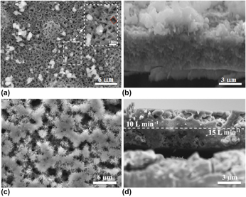
High lithium reversibility and high cycling stability in LIB conversion cathode materials such as FeF2 and FeS2, made with different techniques other than spray pyrolysis, were attributed to the formation of <5 nm diameter Fe nanoparticles in close proximity to the converted LiF phase, and to the deposition of FeS2 nanoparticles, respectively [Reference Zhu, Fan, Suo, Luo, Gao and Wang50, Reference Wang, Robert, Chernova, Pereira, Omenya, Badway, Hua, Ruotolo, Zhang, Wu, Volkov, Su, Key, Whittingham, Grey, Amatucci, Zhu and Graetz87, Reference Ma and Garofalini88, Reference Al-khateeb, Lind, Santos-Ortiz, Shepherd and Jones89]. The nanoparticles have a large surface area for active film–electrolyte interaction. Therefore, porous FeS2 films could be helpful in improving the battery performance compared to dense ones. Pores could lead to enhanced surface area and contact area between the FeS2 film and the electrolyte. Unlike the long cathode fabrication process (section Introduction) for FeS2 particles, the porous FeS2 films deposited by spray pyrolysis on steels and aluminum microgrid current collectors need no further processing. Additionally, no binder or slurry is needed, which might lead to superior battery performance. In our previous work [Reference Al Khateeb and Sparks44], spray pyrolysis was applied to fabricate nongraded films, which exhibited nearly constant porosity throughout the film thickness [Figs. 1(a) and 1(b)]. Very encouraging capacity values were reported [Reference Al Khateeb and Sparks44], which were comparable to the literature findings but with the aforementioned processing privileges.
SEM microstructural images of the FeS2 films deposited with a pulse time to interval time ratio of 4 min:8 min using the chloride iron precursor and Ar carrier gas flow rate of (a) 15 L/min for 16 min actual deposition, (b) the cross section of the film in (a). Note the diamond-shaped pores in the box of (a), (c) 15 L/min for 8 min actual deposition and then 10 L/min for another 8 min actual deposition, (d) the cross-section of the film in (c).
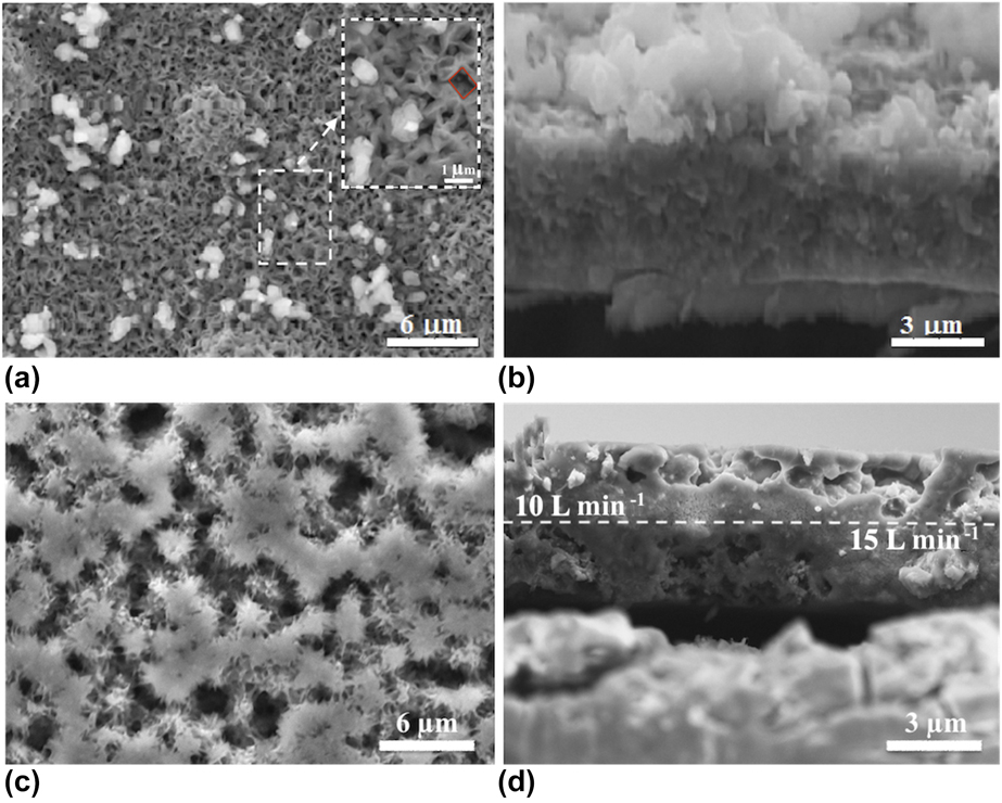
The deposition parameters and precursors were kept the same as those used in our previous work to allow for comparison [Reference Al Khateeb and Sparks44]. However, to deposit a porosity-graded FeS2 film, a multiple-step deposition was used by changing the carrier gas flow rate during the interval time (the rest time between successive depositions). The ratio 1 M:1 M of FeCl3:NH2CSNH2 and deionized H2O in the volume ratio of 0.07:0.15:0.78 were used for FeS2 deposition at 400 °C. The substrate–nozzle distance was 5 cm and the total deposition time was 16 min. The films were deposited at an interval time:pulse time of 4 min:8 min. For the nongraded porous film, the carrier gas flow rate of Ar was 15 L/min [Figs. 1(a) and 1(b)] and the film was porous throughout the thickness with an interconnected diamond-like structure and the film thickness was 5.7 μm. For the porosity-graded film, an Ar flow rate of 15 L/min was applied for a total deposition time of 8 min and then a flow rate of 10 L/min was applied for another 8 min. Another film was deposited but by applying 10 L/min and then 15 L/min to investigate the effect on film grading. The deposited films were then sulfurized in an evacuated quartz ampule using 100 mg sulfur flakes for 4 h at 10−4 torr. Figure 1(c) shows the surface morphology of the film deposited at 15 and then 10 L/min. The film morphology shows a porous structure with larger pores (for the surface layer deposited at 10 L/min) as compared to the film deposited at 15 L/min [Fig. 1(a)].
Our pore-graded structure is consistent with the literature findings in fields unrelated to LIBs. For example, researchers deposited platinum [Reference Paschos, Choi, Efstathiadis and Haldar22] by spray pyrolysis and found that the deposited platinum’s density increased (less porous structure) by increasing the flow rate. On the other hand, for MgO films [Reference Bian, Li, Chen, Gao and Yu26], the density increased by increasing the substrate temperature. This was attributed to the enhanced diffusion made possible by the higher temperature. The increased diffusion allowed mass to be transported and fill in the internal defects. In comparing these two studies, it should be noted that flow rate and substrate temperature are inversely correlated. This leads to an apparent contradiction since a higher flow rate would be expected to decrease substrate temperature for Pt deposition leading to higher porosity. Of course, the comparison might not be valid because very different materials were deposited. In fact, this might suggest that different materials behave differently during spray deposition leading to different morphologies.
In this work, the surface morphology of the film layer deposited at low Ar flow rate (10 L/min) in Fig. 1(c) shows larger pore sizes compared to the film deposited at higher Ar flow rate (15 L/min) in Fig. 1(a). The low flow rate of Ar maintains higher substrate temperature when compared to the high flow rate of Ar. This low material deposition at low flow rates could be attributed to two factors. First, the low flow rate carries less precursor material compared to the high flow rate. Second, the higher substrate temperature at the low flow rate makes the droplet evaporation more rapid, leading to smaller droplets that are better able to flow with the gas away from the substrate (higher thermophoretic velocity). Therefore, it is possible that the low material deposition at the low Ar flow rate dominates over the higher diffusion energy also present at low flow rates. The result of these mechanistic competitions is a more porous structure as seen in Fig. 1(c).
For both flow rates, it seems the temperature is appropriate for the material to be deposited in a thin film form according to the third mode of spray deposition. According to the spray pyrolysis deposition modes [Reference Milan93], in the third mode thermal decomposition of dry precipitates starts on their way to the substrate and mainly vapor arrives at the substrate surface leading to film formation. In the second mode, dry precipitates come to the substrate surface, where thermal decomposition takes place. Therefore, for the FeS2 film deposited at 15 L/min [Fig. 1(a)], we have a thin film deposition according the second and third modes of deposition where a film in addition to particles was obtained.
There are five possible modes of film growth, which depends upon factors such as lattice misfit between substrate and film, growth temperature, adhesion energy, and more [Reference Chopra94, Reference Herman, Richter and Sitter95, Reference Thompson, Floro and Smith96]. Given that the substrates and deposited films in this work are held constant, then the variable that might be affecting the growth mode is the temperature, which is in turn influenced by the flow rate of the of carrier gas. The films represented in Figs. 1(a) and 1(c) seem to follow the Stranski–Krastanov [Reference Chopra94], or layer plus island growth modes. Briefly, in layer-by-layer or Frank–van der Merwe [Reference Herman, Richter and Sitter95], growth occurs when the binding between film atoms is less than that between the film atoms and the substrate. In island or Volmer–Weber growth [Reference Thompson, Floro and Smith96], small clusters are nucleated directly on the substrate surface; the clusters then grow into islands. This type of growth occurs when the film atoms are more strongly bound to each other than to the substrate. Stranski–Krastanov mode is an intermediate case between the layer and island growth modes. In other words, the Stranski–Krastanov mode starts with Frank–van der Merwe and after few monolayers of deposition, the growth mode follows the Volmer–Weber growth mode. Therefore, in the Stranski–Krastanov mode after forming one or more monolayers, further layer growth becomes unfavorable and islands are formed on top of this intermediate layer, which gives the porous structures in Figs. 1(a) and 1(c). The formation of porous thin films of different materials were related to the aforementioned growth modes in the literature [Reference Ta, Perello, Duong, Han, Gorantla, Nguyen, Bachmatiuk, Rotkin, Lee and Rümmeli97, Reference Eaglesham and Cerullo98, Reference Shrestha, Gu, Tran, Tapily, Baumgart and Namkoong99, Reference Kaiser100]. Ta et al. [Reference Ta, Perello, Duong, Han, Gorantla, Nguyen, Bachmatiuk, Rotkin, Lee and Rümmeli97] grew graphene layer on polished copper through CVD. They schematically represented the growth of copper as following either the Stranski–Krastanov or Volmer–Weber growth mode depending on the used ratios of CH4 to H2. Although not explicitly reported, the schematic representation of both growth modes reported in the literature show pore formation [Reference Ta, Perello, Duong, Han, Gorantla, Nguyen, Bachmatiuk, Rotkin, Lee and Rümmeli97, Reference Eaglesham and Cerullo98]. Shrestha et al. [Reference Shrestha, Gu, Tran, Tapily, Baumgart and Namkoong99] deposited platinum by the atomic layer deposition (ALD) on Si substrates. It is reported that the coalescence of isolated islands occurs at a percolation thickness. This thickness depends on the substrate temperature, which affects the surface diffusion of the film material [Reference Kaiser100]. Therefore, by limiting the number of ALD deposition cycles to remain within the Volmer–Weber island growth phase, Shrestha et al. [Reference Shrestha, Gu, Tran, Tapily, Baumgart and Namkoong99] grew porous discontinuous platinum films with high surface area. For the films in this work, it can be seen that 15 L/min [Fig. 1(a)] produced a more layer-like growth mode and 10 L/min [Fig. 1(c)] produced a more island-like growth mode producing larger pores.
A cross-sectional image of films deposited at 15 L/min [Fig. 1(b)] show that the pore size is uniform throughout film thickness. However, for the film deposited at the 15–10 L/min, the film shows a porosity-graded structure as can be seen from the cross-sectional image in Fig. 1(d). It is clear that smaller pores are formed on the substrate side where deposition was performed at a flow rate of 15 L/min and larger pores on the electrolyte side where deposition was performed at a flow rate of 10 L/min. The larger pores on the electrolyte side could be beneficial for larger mass transport of electrolyte into the film, which would improve the conductivity and diffusivity of lithium ions through the electrode [Reference Liu, Guan and Liu70]. The smaller pore sizes on substrate side could be beneficial to facilitate charge transfer, potentially reducing internal resistances and further improving rate capabilities [Reference Vu, Qian and Stein74].
The areal fraction of porosity for the films was calculated using ImageJ (Madison, Wisconsin) [Reference Schneider, Rasband and Eliceiri101]. For the film deposited at 15 L/min [Fig. 1(a)], the porosity percentage was calculated to be 18% ± 1. For the film deposited at 15–10 L/min [Fig. 1(c)], the porosity percentage was calculated from the film surface images to be 20% ± 1 for the layer deposited at 15 L/min and 25% ± 1 for the layer deposited at 10 L/min. The layer deposited at 15 L/min shows a porosity percentage close to the one obtained for the nongraded film deposited primarily at 15 L/min [Fig. 1(a)] and this confirms that the FeS2 deposition by spray pyrolysis technique is a reproducible one. If the areal fraction percentages are proportional to the volumetric percentages, V, then the density, ρ, of the FeS2 film deposited at 15 L/min will be reduced from the theoretical density, ρTD, to 5.01 g/cm3 × (1.00 − 0.18) = 4.1 g/cm3. For the film deposited at 15–10 L/min, the density is calculated based on the density of a composite according to Eq. (1) below,
 $${\rho _{{\rm{composite}}}} = {\rho _{{\rm{15}}\;{{\rm{L}} / {{\rm{min}}}}}}\;{V_{{\rm{15}}\;{{\rm{L}} / {{\rm{min}}}}}} + {\rho _{{\rm{10}}\;{{\rm{L}} / {{\rm{min}}}}}}\;{V_{{\rm{10}}\;{{\rm{L}} / {{\rm{min}}}}}}\quad .$$
The volume fractions for the pore-graded film was also measured from the cross-sectional image [Fig. 1(d)] assuming proportionality between linear and volumetric ratios of the deposited layers. The thickness of the layer deposited at 15 L/min was 2.6 μm and for the layer deposited at 10 L/min was 2.4 μm [Fig. 1(c)]. Based on the measured thicknesses, the volume fraction for the 15–10 L/min sample was calculated as 52% for the layer deposited at 15 L/min and 48% for the layer deposited at 10 L/min. Given that
 $${\rho _{{\rm{15}}\;{{\rm{L}} / {{\rm{min}}}}}} = 5.01 \times \left( {1.00 - 0.20} \right)\quad ,$$
 $${\rho _{{\rm{10}}\;{{\rm{L}} / {{\rm{min}}}}}} = 5.01 \times \left( {1.00 - 0.25} \right)\quad ,$$
the density of the composite pore-graded FeS2 film represented in Fig. 1(d) was calculated to be 3.9 g/cm3.
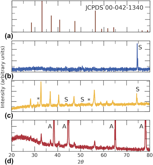
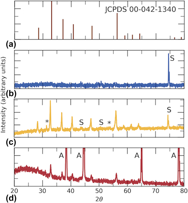
The X-ray diffractometer (XRD) patterns of the as-deposited films, irrespective of the applied flow rate, showed only peaks corresponding to the substrate, which suggests the as-deposited films are completely amorphous. The XRD pattern of the as-deposited film at 15–10 L/min is shown in Fig. 2(b). Previous researchers have shown that to achieve crystalline FeS2, the deposited films need to be annealed in the presence of sulfur [Reference Al Khateeb and Sparks44, Reference Li, Caban-Acevedo, Girard and Jin45, Reference Nakamura and Yamamoto102, Reference Yamamoto, Nakamura, Seki, Li, Hashimoto and Nakamura103, Reference Raturi, Waita, Aduda and Nyangonda104]. The XRD pattern of the sulfurized 15–10 L/min pore-graded sample is shown in Fig. 2(c). The sulfurization led to the formation of FeS2-dominated film, although a few FeS peaks were detected. The FeS2 peaks match those of the standard for FeS2 [JCPDS card number 42-1340, Fig. 2(a)]. The XRD patterns (not shown) of the nongraded film deposited at 15 L/min showed similar XRD patterns.
XRD patterns of spray deposited and sulfurized films with substrate (S) for 316L and (A) for aluminum microgrid, FeS (*). (a) FeS2 with JCPDS card number 42-1340, (b) as-deposited film on 316L from FeCl3 and NH2CSNH2 precursors with 15–10 L/min, (c) film deposited on 316L from FeCl3 and NH2CSNH2 precursors with 15–10 L/min and sulfurized in sealed ampoule, (d) film deposited on aluminum microgrid from FeCl3 and NH2CSNH2 precursors with 15 L/min and sulfurized in sealed ampoule.
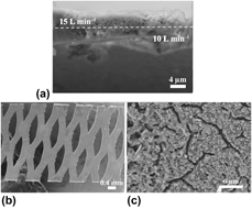
To further investigate the effect of pore-graded FeS2 on the performance of LIBs, another FeS2 film was deposited by spray pyrolysis. However, the aim of this new film was to have an inverted porosity gradient relative to our previous sample, that is, larger pores on the substrate side and smaller pores on the electrolyte side. This inverted structure was achieved by applying a 10 L/min and then 15 L/min of Ar flow rate. Figure 3(a) is the cross section of the deposited film, which indeed shows large pores for the layer deposited on the substrate side at 10 L/min and small pores on the electrolyte side for the layer deposited at 15 L/min. Once again this confirms that the spray pyrolysis technique is able to achieve a variety of film architecture with ease and with very good reproducibility.
Cross-sectional SEM microstructural images of the FeS2 film deposited with a pulse time to interval time ratio of 4 min:8 min using the chloride iron precursor and (a) 316L substrate and Ar carrier gas flow rate of 10 L/min for 8 min actual deposition and then 15 L/min for another 8 min actual deposition, (b) aluminum microgrid substrate, (c) aluminum microgrid and Ar carrier gas flow rate of 15 L/min for 16 min.
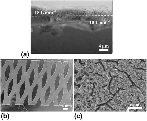
Another variation in this work is the deposition of FeS2 by spray pyrolysis on a porous current collector. The porous current collector was reported to provide rapid ion and electron transport pathways while also accommodating stresses due to volume change during lithium insertion and de-insertion [Reference Zhang, Yu and Braun85]. For this purpose, porous aluminum microgrids [Fig. 3(b)] were used as the substrates to study this effect on battery performance. FeS2 film was spray deposited at 15 L/min for a total deposition time of 16 min followed by sulfurization in sealed ampoules. The surface morphology of the deposited film is shown in the scanning electron microscope (SEM) image of Fig. 3(c). A porous film but with a different morphology compared to the steel substrates [Fig. 1(a)] was obtained. This could be attributed to the different thermal conductivities of aluminum compared to 316L steel, which would affect the substrate temperature during deposition. Aluminum has a larger thermal conductivity than steel, which renders the substrate hotter during deposition compared to 316L steel at the same deposition conditions. At the same time, the higher temperature allows for the deposition of less precursor. Accordingly, there will be a competition between the less material being deposited and the enhanced diffusion in controlling the porosity of the deposited film. In addition, the heat flow in the air-filled diamond-shaped pores is different from that in the substrate itself. This heat flow difference may affect the flow of the carrier gas with the precursor and the diffusion energy available for the deposited film. All of these variables together contributed to the surface morphology shown in Fig. 3(c). The thickness of the deposited film was measured to be 1.3 μm, which is less than the thickness of FeS2 deposited on 316L substrate [Fig. 1(a)] for the same total deposition time of 16 min. This suggests the dominance of the low deposited material over the high temperature diffusion leading to the porous morphology. Nevertheless, more investigation is required to decide how these variables and how the substrate porosity would be controlled to control the pore’s morphology.
The XRD pattern [Fig. 2(d)] of the film deposited on the Al microgrid and later sulfurized confirms the desired FeS2 phase. The peak intensity detected is less than the ones shown for the films deposited on 316L steel [Fig. 2(a)] due to the lower thickness of the deposited film.
Electrochemical characterization
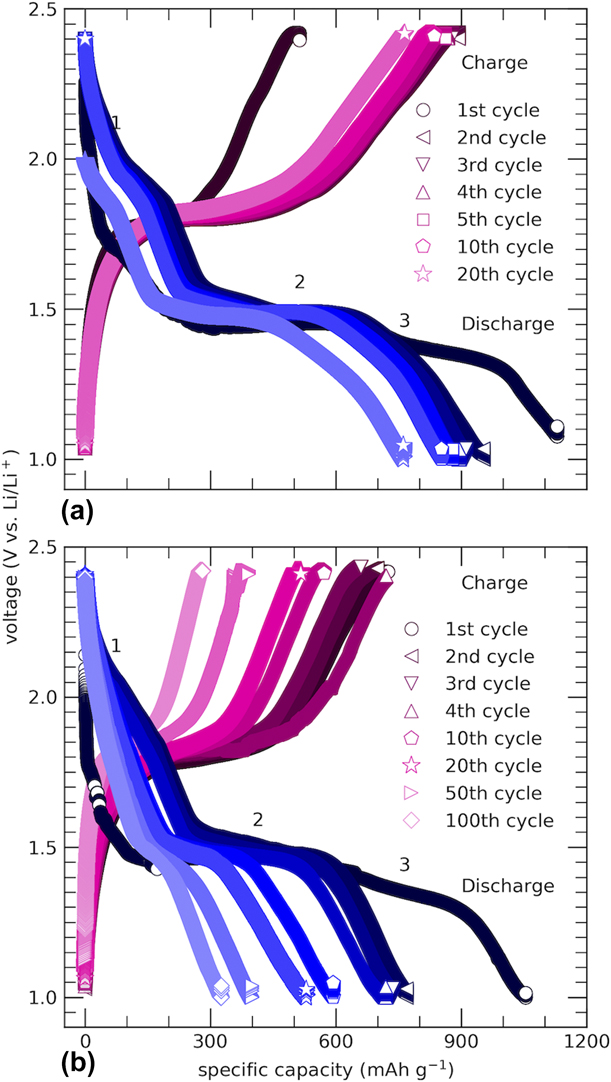
The discharge–charge cycling profiles of the deposited and sulfurized films on 316L are shown in Fig. 5, where the cycling was performed at C/10 (or 89.4 mA/g; in another words, a current of 89.4 mA is needed to entirely discharge or fully charge the battery in 10 h). Figure 4(b) shows the discharge–charge profile for the FeS2 film deposited at 15 L/min. A first discharge capacity of 1050 mA h/g was obtained, which is higher than the theoretical capacity of FeS2 (894 mA h/g). This high first discharge capacity suggests the formation of a SEI layer caused by electrolyte decomposition as found by other researchers [Reference Liu, Lu, Song, Yu, Lou and Paik105, Reference Wang, Yang, Chou, Liu, Zhang, Zhao and Dou106, Reference Sina, Nam, Su, Pereira, Yang, Amatucci and Cosandey107]. The irreversible capacity loss after the first cycle was also attributed to the formation of an SEI layer [Reference Liu, Lu, Song, Yu, Lou and Paik105, Reference Wang, Yang, Chou, Liu, Zhang, Zhao and Dou106, Reference Sina, Nam, Su, Pereira, Yang, Amatucci and Cosandey107]. 400 mA h/g after 50 cycles and 321 mA h/g after 100 cycles were obtained [Fig. 4(b)].
Discharge–charge profiles of the FeS2 films deposited from the FeCl3 and NH2CSNH2 precursors. The films were cycled at C/10 (89.4 mA/g) and at room temperature in the voltage window 1.0–2.4 V using 1 M LITFSI in DOL:DME at a volume ratio 1:1 using a carrier gas flow rate of (a) 15 L/min and then 10 L/min (porosity-graded), and (b) 15 L/min (nongraded porous).
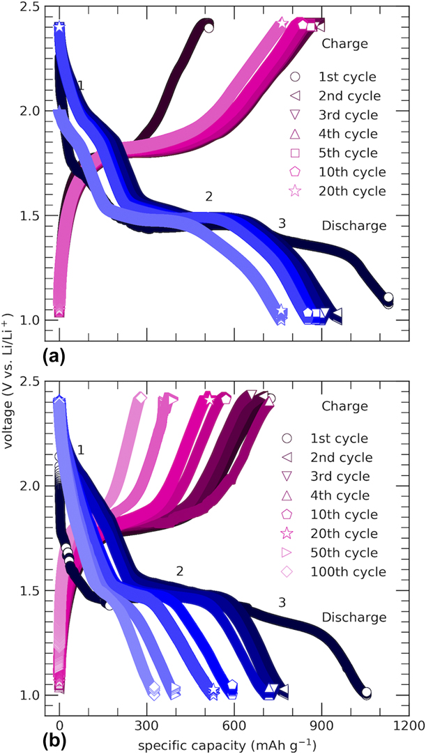
The lithiation (discharge) of FeS2 proceeds in two steps according to the following two reactions [Reference Li, Caban-Acevedo, Girard and Jin45, Reference Fong, Dahn and Jones49, Reference Evans, Piper, Kim, Han, Bhat, Oh and Lee52, Reference Yersak, Macpherson, Kim, Le, Kang, Son, Kim, Trevey, Oh, Stoldt and Lee53]:
 $${\rm{Fe}}{{\rm{S}}_2} + 2{\rm{Li}} \to {\rm{L}}{{\rm{i}}_2}{\rm{Fe}}{{\rm{S}}_2}\quad ,$$
 $${\rm{L}}{{\rm{i}}_{\rm{2}}}{\rm{Fe}}{{\rm{S}}_{\rm{2}}} + {\rm{2Li}} \to 2{\rm{L}}{{\rm{i}}_{\rm{2}}}{\rm{S}} + {\rm{Fe}}\quad .$$
The above two equations proceed simultaneously at room temperature due to the low diffusion of Li+ into pyrite. The low diffusion causes one voltage plateau at about 1.5 V to be obtained in the first discharge cycle. This first voltage plateau was observed for FeS2 powder prepared by different techniques irrespective of the cycling rate as we found earlier in our previous work [Reference Al Khateeb and Sparks44]. For the subsequent cycles, a second inclined region was also observed starting at about 2 V. In the literature, this region has been attributed to lithium intercalation and reduction of S, pyrrhotite, and marcasite (other phases of FeS2) formed during charging [Reference Li, Caban-Acevedo, Girard and Jin45, Reference Fong, Dahn and Jones49, Reference Zhu, Fan, Suo, Luo, Gao and Wang50, Reference Choi, Kim, Kim, Cho, Cho, Ahn, Ahn, Ryu and Gu51, Reference Evans, Piper, Kim, Han, Bhat, Oh and Lee52, Reference Yersak, Macpherson, Kim, Le, Kang, Son, Kim, Trevey, Oh, Stoldt and Lee53, Reference Cheng, Wang, Lin, Li, Qiu, Zheng, Zhao and Zhang59, Reference Montoro and Rosolen108]. In our work, similar plateaus were observed for the nongraded FeS2 films deposited at 15 L/min [marked 1 and 2 in Fig. 4(b)]. However, in the first discharge cycle, a new region was detected [marked 3 in Fig. 4(b)]. The plateaus 2 and 3 were at about 1.50 V and 1.46 V, respectively. The new region indicates that in addition to formation of Li2S and Fe [Eq. (3)], there may be other side reactions occurring during the first discharge. Such side reactions imply FeS2 will not be fully recovered in the first charge, causing, in addition to the SEI contribution, low subsequent discharge capacities. Subsequent cycles consisted of an inclined region starting at about 2 V down to about 1.5 V marked as 1 in Fig. 4(b). Such inclined region also indicates that FeS2 was not fully recovered in the first charge, causing the capacity fading in subsequent cycles.
The charge–discharge profiles for the porosity-graded FeS2 films deposited using 15–10 L/min show similar trends [Fig. 4(a)] to the ones discussed for the nongraded film [Fig. 4(b)]. Interestingly, the porosity-graded film show larger capacities and lower capacity fade compared to the nongraded structure. When cycling FeS2 films, the lithium ions react with FeS2 during the discharge and during charging the formation of soluble sulfur ions is unavoidable [Reference Evans, Piper, Kim, Han, Bhat, Oh and Lee52, Reference Liu, Yuan, Qiu and Liu57]. The insulating nature and poor electrical contacts of the soluble ions lead to poor electrochemical accessibility. Therefore, high charge transfer impedance leading to capacity fade is caused by these soluble ions. On the other hand, if the reaction of lithium ions with FeS2 was enhanced, it may compensate for the capacity loss by fading. This can be achieved by increasing the surface area, i.e., by preparing a porosity-graded structure. The larger pores formed on the electrolyte side improved the conductivity and diffusivity of lithium ions through the electrode and, therefore, facilitated fast lithium reaction with FeS2 [Reference Liu, Yuan, Qiu and Liu57, Reference Liu, Guan and Liu70]. The smaller pores on the substrate side facilitated the charge transfer, potentially reducing internal resistances, and further improving rate capabilities [Reference Vu, Qian and Stein74]. Accordingly, high capacity with improved capacity retention was achieved in this porosity-graded structure design as will be seen from the cycling stability test below.
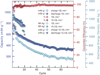
The cycling stability of the nongraded and the porosity-graded films is shown in Fig. 5. The nongraded film discharge capacity faded rapidly during the first few cycles. 1084 mA h/g and 692 mA h/g for the first and the 5th discharge cycles were obtained, respectively. The capacity loss per cycle for this nongraded film would be 7.2% per cycle for the first 5 cycles. For the porosity-graded film, a first discharge capacity of 954 and 879 mA h/g for the 5th cycle gives a capacity loss of only 1.6% per cycle for the first 5 cycles. This confirms the efficiency of the porosity-graded design in enhancing capacity retention and in improving the capacity values. The porosity-graded film has a 20th discharge capacity of 754 mA h/g compared to 529 mA h/g for the nongraded structure. It is to be emphasized that given that our films are binder- and conductor-free, the capacity values we are reporting in this work are superior to those reported in the literature, which rely on significant carbon and binder additives. 20th discharge energy density values of 796 W h/kg and 1042 W h/kg for the nongraded and the porosity-graded films respectively, were obtained. A coulombic efficiency of about 98% was retained for both design structures.
Electrochemical performance of the nongraded and porosity-graded FeS2 films deposited from the FeCl3 and NH2CSNH2 precursors. The figure shows the cycling stability of the films including discharge and charge capacity, coulombic efficiency, and discharge energy density versus cycle numbers.
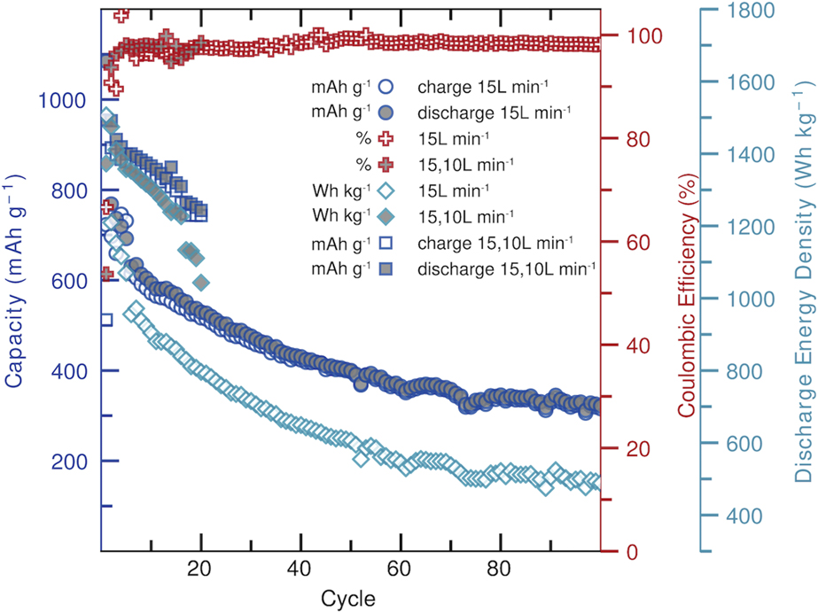
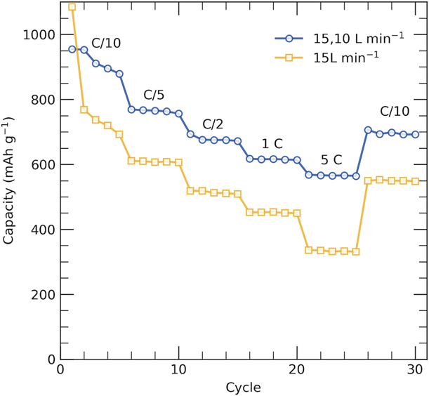
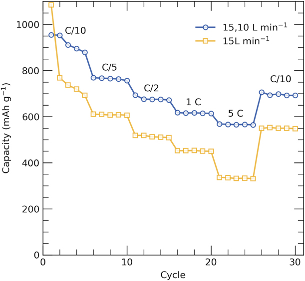
Figure 6 shows the rate performance test of the nongraded and porosity-graded films. The films were cycled at slow C rates (C/10) and at rates as fast as 5C. Irrespective of the applied C rate, the capacities of the porosity-graded film were larger at all times. Both film designs show an outstanding rate performance when cycling at C/10 up to 5C and then recycle at C/10. The nongraded film showed a capacity of 692 mA h/g for the 5th cycle at C/10, and when recycled at C/10, the capacity was 548 mA h/g in cycle 1. The 5th cycle at the first C/10 was chosen to exclude the effect of the SEI contribution to the capacity. 879 mA h/g and 691 mA h/g are the capacities of the porosity-graded film in the 5th and first cycles when cycled and recycled at C/10, respectively. The performance test interestingly shows high efficiency of the porosity-graded film at high C rate (5C) compared to the nongraded film. In other words, the last cycle at 1C gave a capacity of 613 mA h/g and the first cycle at 5C gave a capacity of 568 mA h/g with capacity retention of 92.7%. For the nongraded film, the capacities were 449 mA h/g and 336 mA h/g in the last cycle at 1C and in the first cycle at 5C, respectively, with a capacity retention of only 74.8%. This suggests that our porosity-graded structure is suitable for high rate applications. The high rate advantages may benefit EV and HEV applications, as well as applications requiring pulses of high power, such as those in certain communication devices [Reference Vu, Qian and Stein74]. Nevertheless, further investigation is required to confirm the suitability of pore-graded thin film architecture for the transportation applications.
Rate performance of the nongraded and porosity-graded films cycled at different rates.
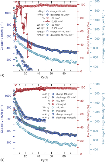
The electrochemical performance of the inverse porosity-graded structure represented in Fig. 3(a) is shown in Fig. 7(a). Without a doubt, the battery performance suffers with an inverted porosity-graded structure design. The large pores on the substrate side suggests low adhesion, which would render the film weak causing it to peel off during cycling. As explained earlier, the first deposited layer at 10 L/min is dominated by the island growth (Volmer–Weber [Reference Thompson, Floro and Smith96]) mode, which gives the large pores. In this mode, the film atoms or molecules are more strongly bound to each other than to the substrate; therefore, the film is more likely to peel off during cycling and this is what was actually obtained (not shown). Accordingly, and based on our observations of the cycled films, the 15–10 L/min porosity-graded structure is the recommended structure over the 10–15 L/min porosity-graded structure.
Electrochemical performance of the (a) nongraded and inverse porosity-graded FeS2 films deposited on 316L and Ar carrier gas flow rate of 10 L/min for 8 min actual deposition and then 15 L/min for another 8 min actual deposition and (b) nongraded FeS2 films deposited on 316L and aluminum microgrid at 15 L/min. FeCl3 and NH2CSNH2 precursors were utilized in both (a) and (b). The figures show the cycling stability of the films including discharge and charge capacity, coulombic efficiency, and discharge energy density versus cycle numbers.
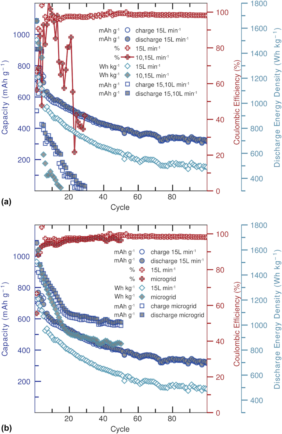
The cycling performance of the FeS2 film deposited at 15 L/min on aluminum micro-grid is shown in Fig. 7(b). The porous substrate would allow for more film–electrolyte interaction, which provides rapid ion and electron transport pathways. It also improves the electrical contact with the active material. Therefore, the film deposited on the aluminum microgrid is showing larger capacities and energy densities compared to the film deposited on 316L. The different substrate materials and the different film thicknesses would raise concerns for a direct comparison. Nevertheless, we clearly see that the microgrids are showing improved cycling stability after 20 cycles compared to 60 cycles for the film deposited on 316L. Overall, the battery performance was improved by using the microgrid but this improvement was not as much as the improvement obtained by using the porosity-graded film (Fig. 5).
Conclusions
To improve the battery performance in terms of capacity and energy density, a high contact area between the electrolyte and the electrode and good structural stability should be obtained [Reference Wen, Wei, Yang and Shen54, Reference Liu, Wen, Wang, van Aken, Maier and Yu64]. Such structures have short diffusion distances for Li+ ions and have been investigated by researchers who synthesized FeS2 with different morphologies [Reference Li, Caban-Acevedo, Girard and Jin45, Reference Zhu, Fan, Suo, Luo, Gao and Wang50, Reference Yoder, Tussing, Cloud and Yang55, Reference Cheng, Wang, Lin, Li, Qiu, Zheng, Zhao and Zhang59, Reference Chen, Wang, Wang, Wan, Liu and Qian63, Reference Liu, Wen, Wang, van Aken, Maier and Yu64] but not in a porosity-graded thin film form. The fabrication procedures reported in the literature were either complex, requiring further processing of FeS2 to make the cathode, or relied necessarily on nonelectrochemically active materials, which will limit the energy density of the cathode. In addition, the use of a conductor-like carbon black or acetylene black contributes to the reported capacity values, and accounting for these additives would reduce the observed values for previous literature studies.
In this work, porosity-graded films that are free of binder and conductor were deposited on 316L steel and aluminum microgrid substrates by spray pyrolysis. Spray pyrolysis is a simple, nonvacuum, fast, scalable, and an inexpensive film deposition technique. The films were followed by sulfurization in evacuated quartz ampules leading to crystallized FeS2 films. The sulfurized films were then assembled into coin cells without any further processing. The films were graded in porosity with large pores close to the electrolyte side and small ones close to the substrate side. The larger pores on the electrolyte side could be beneficial for larger mass transport of electrolyte into the film, which would improve the conductivity and diffusivity of lithium ions through the electrode [Reference Liu, Guan and Liu70]. The smaller pore sizes on the substrate side could be beneficial to facilitate charge transfer, potentially reducing internal resistances and further improving rate capabilities [Reference Vu, Qian and Stein74]. The capacity values reported in this work were based on the active material unlike what was found in the literature. The obtained results for the porosity-graded structure, i.e., the one with large pores on the electrolyte side and small ones on the substrate side, showed superior capacities to any of those reported in the literature findings. Interestingly, this porosity-graded structure showed an outstanding performance in keeping high capacity at high C rates, which would be beneficial for EV and HEV applications [Reference Vu, Qian and Stein74]; however, further investigation is required in this field.
The inverted porosity-graded structure failed because of the film peeling off during cycling due, probably, to the weak bonding of the deposited film atoms with the substrate. The use of porous substrates (aluminum microgrids) helped in improving capacity retention and the deposition of porosity-graded films on such porous substrate may improve the capacities even further. This will be the next steps in our future investigation.
The obtained results confirm that spray pyrolysis can be a reliable technique for commercial fabrication of FeS2 in LIBs. Nevertheless, more investigation is required to better understand what happens for the film during cycling, that is, how the film swells and contracts during cycling and how this would affect the film cyclability. Changing porosity content, size, and gradient and how it would affect the performance of LIBs is another aspect of interest to be investigated.
Methodology
Synthesis of FeS2 films
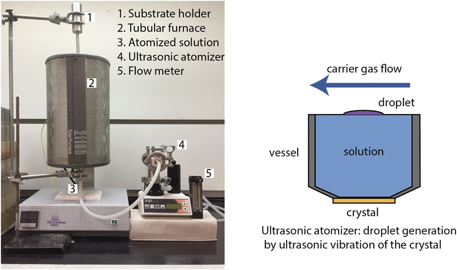
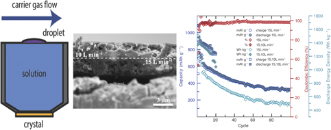
FeS2 films were deposited by spray pyrolysis deposition technique using a 2.4 MHz Sonaer 241PG particle generator in a vertical-up deposition configuration (see Fig. 8). The vertical-up configuration has the advantage of selecting preferentially small droplets for deposition [Reference Mwakikunga90] and, therefore, small deposited crystals.
Spray pyrolysis setup. (1) Substrate holder, (2) tubular furnace, (3) atomized precursor solution carried by Ar gas, (4) ultrasonic atomizer which atomizes the precursor solution (see schematic on right showing precursor solution and a crystal that vibrates to generate the droplets), and (5) carrier gas flow meter. “Reprinted with permission from [Reference Al Khateeb and Sparks44]”.

Spray pyrolysis deposition was performed at 400 °C on a 316L stainless steel current collector. The 316L substrates (10 mm × 10 mm × 50 μm, Goodfellow, Coraopolis, Pennsylvania) were cleaned ultrasonically before the deposition using acetone (99.7%, Fisher Chemical, Waltham, Massachusetts) and isopropanol (99.9%, Fisher Chemical) for 10 min each, respectively. Aluminum microgrids (Dexmet Corporation, Wallingford, Connecticut) were also used as current collectors for FeS2 spray deposition. The substrate had a thickness of 25 µm and the gird had a mesh with a diamond shape pores. The diamond shape had an elongated side of about 1.3 mm and a shortened side of about 0.51 mm. The Al substrates were cleaned as explained for the 316L substrates. It is to be mentioned that the suitability of 316L and aluminum as substrates was investigated elsewhere [Reference Khateeb, Lind, Santos-Ortiz, Shepherd and Jones109, Reference Al-khateeb110]. For the formation of FeS2 films, a concentration of 1 M of FeCl3 (97%, Sigma-Aldrich, St. Louis, Missouri), 1 M of NH2CSNH2 (>99%, Sigma-Aldrich), and deionized H2O in the volume ratio of 0.07:0.15:0.78 was used. The applied heating and cooling rates were 3 °C/min, and the carrier gas used was Ar (99.998%, Airgas, Salt Lake City, Utah) at 15 and/or 10 L/min. The substrate–nozzle distance was 5 cm and the total deposition time was 16 min with a pulse time to interval time of 4 min:8 min.
Sulfurization was found to convert amorphous FeS2 films or low sulfur phases into FeS2 [Reference Yamamoto, Nakamura, Seki, Li, Hashimoto and Nakamura103]. The deposited films were sulfurized at 500 °C for 4 h by elemental sulfur flakes (99.998%, Sigma-Aldrich). The applied heating and cooling rates were 1 °C/min. For this purpose, evacuated quartz ampules (12 mm inner diameter and 14 mm outer diameter, and 15 cm long) containing 100 mg sulfur flakes at 10−4 torr were utilized.
Material characterization
The morphology and thickness of the deposited films were investigated using Hitachi Scanning Electron Microscope (SEM, Hitachi High Technologies Corporation, Tokyo, Japan) using a 15 keV accelerating voltage. Thickness measurements for this work were taken from different spots of the sample and the reported values were the average of 15 measurements. A Bruker D2 PHASER X-ray diffractometer (XRD, BRUKER, Billerica, Massachusetts) with Cu Kα radiation (λ = 1.5418 Å) was utilized to characterize the deposited phase(s) through a 2θ scan from 20° to 80°, using 0.7 s/step and 0.02 s/step.
Electrochemical characterization
Coin cell (2032, MTI) batteries were assembled inside a glovebox with argon environment having less than 0.5 ppm H2O and less than 0.1 ppm O2. The cell configuration, which can be found elsewhere [Reference Khateeb, Lind, Santos-Ortiz, Shepherd and Jones109], was composed of a working electrode of FeS2 film deposited on the current collector, a lithium metal chip (99.9%, 15.6 Dia × 0.45t mm, MTI) as a counter and a reference electrode, Celgard H2013 separator (20 μm thick), and 1 M electrolyte composed of lithium bis(trifluoromethylsulfonyl) imide (LiFTSI, >98%, TCI America, Portland, Oregon) in 1,3-dioxolane (DOL, 99.8%, Sigma-Aldrich) and 1,2-dimethoxymethane (DME, 99.5%, Sigma-Aldrich) at a volume ratio of 1:1. The electrolyte’s volume (L) used in the cell relative to the deposited mass of the FeS2 film (g) had a ratio of about 1:38. The LiTFSI is used as an electrolyte in this work based on the literature reports that it gave a superior battery performance compared to the use of LiPF6, the most commonly used electrolyte in batteries with FeS2 cathodes [Reference Zhu, Fan, Suo, Luo, Gao and Wang50, Reference Evans, Piper, Kim, Han, Bhat, Oh and Lee52, Reference Yoder, Tussing, Cloud and Yang55, Reference Hu, Zhang, Zhu, Tao and Chen56].
Cycling stability (discharge–charge cycles) of the assembled cells was investigated galvanostatically using a BioLogic VSP testing machine over a potential window of 1.0–2.4 V versus Li/Li+ at a C rate of C/10. The capacity and the discharge energy density were measured with respect to the weight of the deposited FeS2 film. The weight of the deposited film was calculated from three samples. The calculations were based on cross-sectional SEM measurements of film thicknesses, measured deposition areas (which would be similar to the areas of the of the film substrates), and the theoretical density of the FeS2 (5.01 g/cm3). Nevertheless, the porosity percentage of the films was measured by ImageJ [Reference Schneider, Rasband and Eliceiri101], which is discussed above. The measured capacities and discharge energy density values were then modified to the measured porosities of the deposited films.
Acknowledgments
This work has been conducted during the sabbatical leave granted to Dr. Shadi Al Khateeb from Al-Balqa Applied University (BAU) during the academic year 2017–2018. The authors would like to thank the Arab Fund Fellowship Program–Kuwait and USTAR UTAG program for their financial support and equipment during this work.